Ikea CR10 Enclosure Information
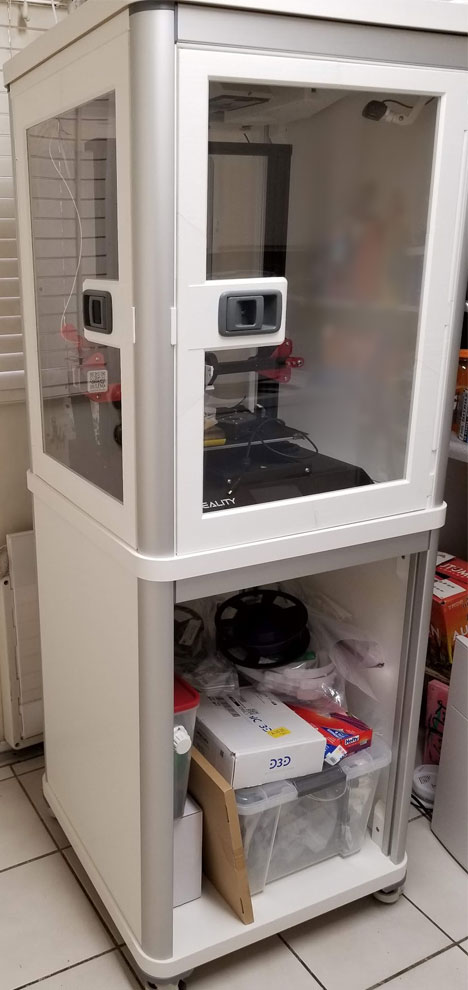
It's been a long time since I finished this project (mostly, since there are a few things I would like to add when I get the time), but I have not posted it due to a few reasons. The first is that it has been so long since I designed and printed it, that I would need to sort through the mess of files and verify which ones were used (I have since changed my ways and have a better system for keeping track of files). I'm also thinking of printing another similar (less expensive) enclosure, which I hope will improve on the design and allow me to better document it. I did not keep track of the costs very well, but I know that it cost at least $600 to build this enclosure, which is too much, even if I think it look cools (and honestly it works very well too). The costs of all the parts has only gone up since I built it, and so has shipping. I believe the total for just the 4545 extrusions and ACM panels these days would probably cost around $600, and that does not include the Ikea parts which have also gone up in price or been discontinued. The Lexan sheets for the windows have also increased by about double from when I bought them. At the prices today, the cost would be ridiculous, and it's not worth my time right now to assemble a package of files and how to info which would be required to post it. So I will be looking for a way to cut the cost on the next version which will house my Voron 2.4. The project will be on the far back burner, but I will post something in my blog when I start working on the 2nd version and get that one printed, with better documentation. The info below is for the 1st, and so far only completed version, and is written as a how-to, but it is unfortunately not gonna be posted due to the reasons explained above.
Doors
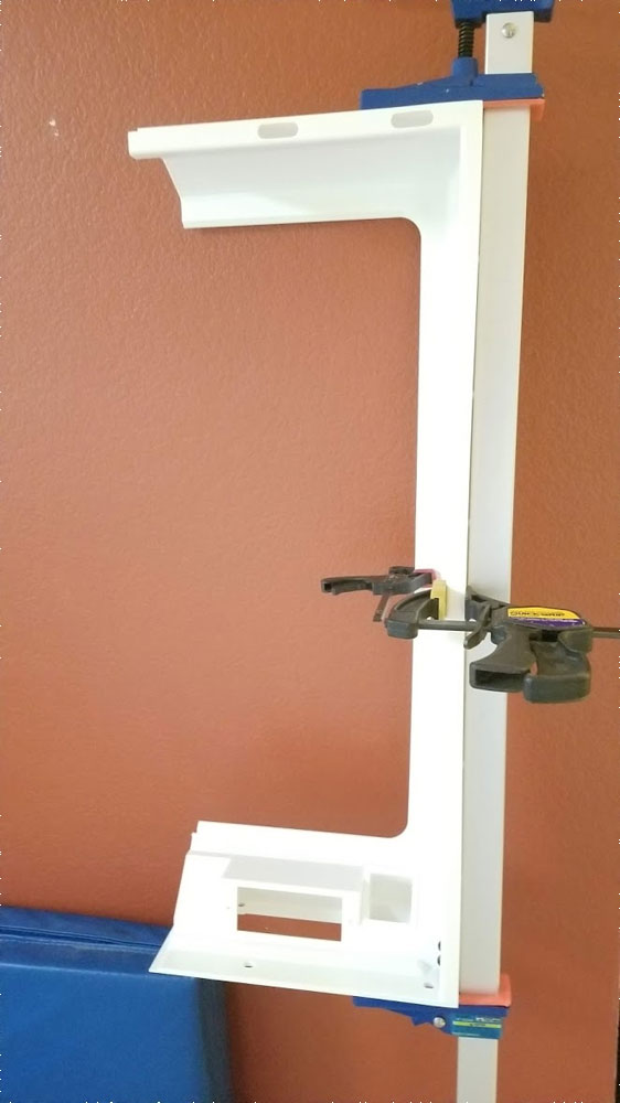
The doors are pinned together with 50-60mm x 5mm steel dowel pins. I used Gorilla Super Glue Gel and Gorilla Glue Clear as the adhesives to hold the doors together (the Gorilla Glue Clear has yellowed over time however so I may try this glue next time). The 1/8" Lexan (Plexiglass) sheet used is approximately 457x665mm for the left side door (the right side door will be shorter). Once all the parts are printed, the latch mechanism can be assembled first.
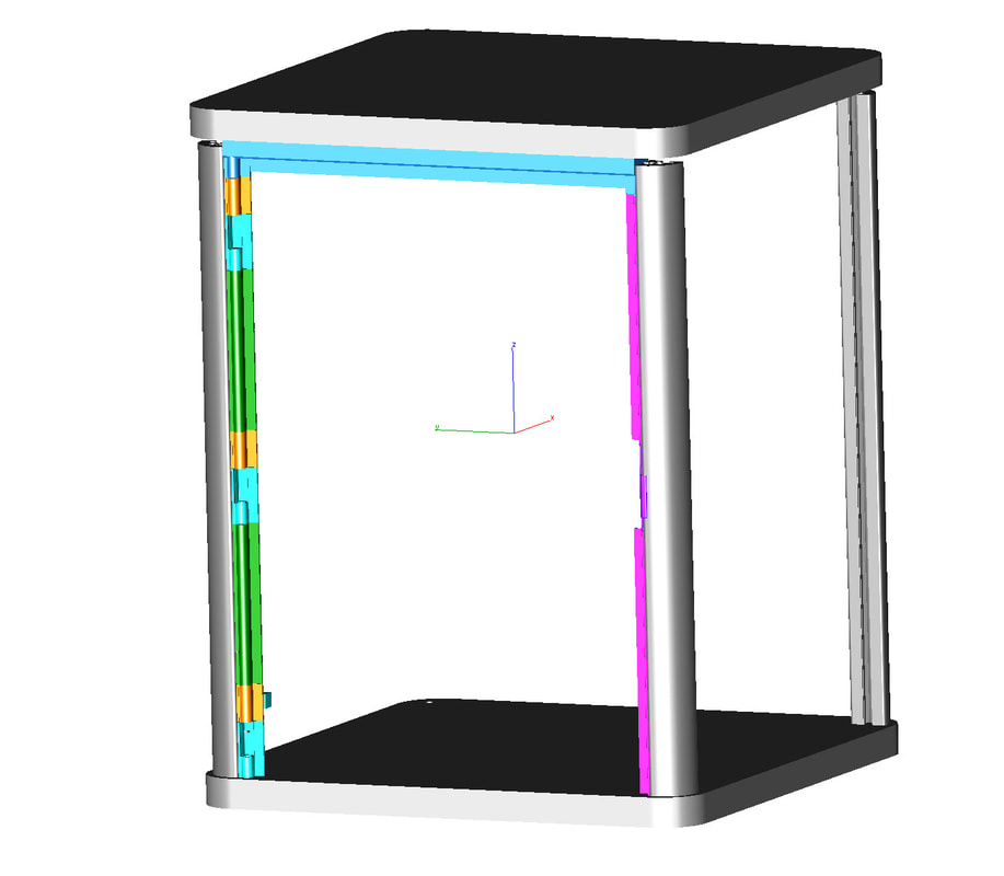
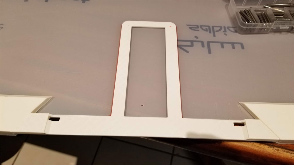
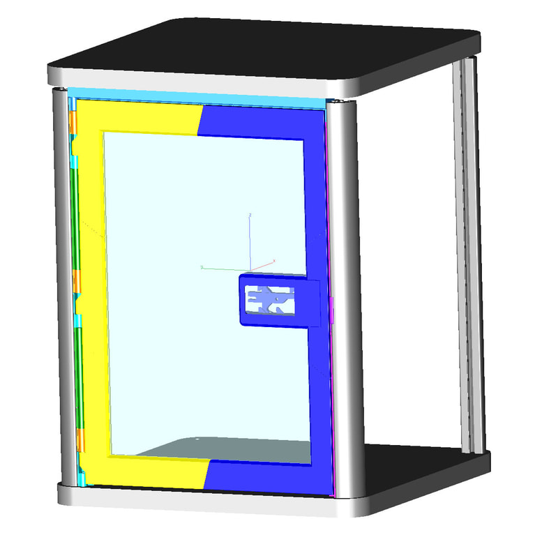
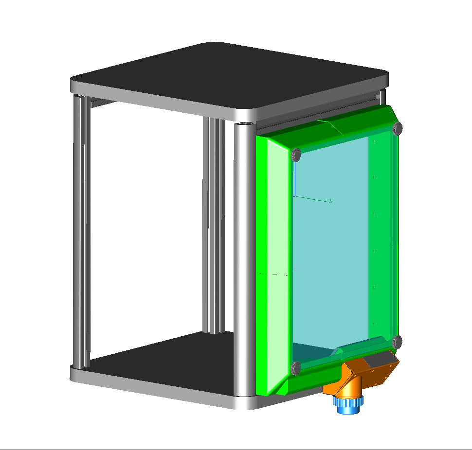
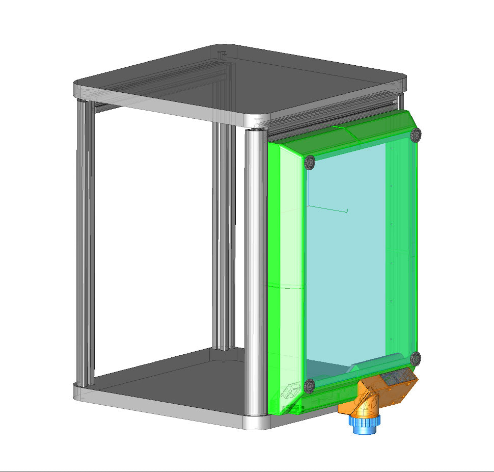
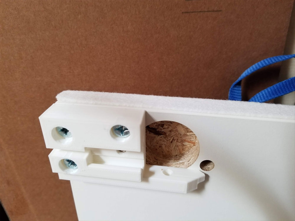
The first step is to install the frame parts, which will allow the door to be hung. These are shown in the pic below. The cyan color parts are the hinge parts, which have a bronze bushing installed (5mm bore, 9mm OD 10mm length). I also placed an M5 washer over the bearing and glued that in with superglue. The orange color parts are actually 2 parts which need to be assembled using M3 hardware. The green color parts are just spacers. At the top there are 3 parts (light blue) which create a top frame for the door. This top frame was glued prior to installation and required some #8 screws which will help secure it to the top of the enclosure. Along the right side of the frame, there are 3 parts. There are 2 spacers in pink (they are not the same size), and in the center in purple is the strike plate for the door latch. All the frame parts are secured to the 4545 extrusions using M5 x 16mm button head screws and M5 T-nuts for 4545 extrusions.
The first step is to install the frame parts, which will allow the door to be hung. These are shown in the pic below. The cyan color parts are the hinge parts, which have a bronze bushing installed (5mm bore, 9mm OD 10mm length). I also placed an M5 washer over the bearing and glued that in with superglue. The orange color parts are actually 2 parts which need to be assembled using M3 hardware. The green color parts are just spacers. At the top there are 3 parts (light blue) which create a top frame for the door. This top frame was glued prior to installation and required some #8 screws which will help secure it to the top of the enclosure. Along the right side of the frame, there are 3 parts. There are 2 spacers in pink (they are not the same size), and in the center in purple is the strike plate for the door latch. All the frame parts are secured to the 4545 extrusions using M5 x 16mm button head screws and M5 T-nuts for 4545 extrusions.
Once the frame parts are assembled, the door can be assembled. After building one door, I will describe the best way I think it should be done.
I assembled the hinge side of the door using 50-60mm 5mm dowel pins, and super glue. First make sure any oils are removed from the dowel pins by cleaning with alcohol. Then Install 2 pins in one side of each part being assembled for the hinge side (there will be a top, middle and bottom). Allow the glue to dry on one side fully, before assembling the parts together. Once the pins are installed for one side of each part, I set up a clamp so that I could tighten the parts together quickly once the glue was laid down. I added some superglue to the mating surfaces and then placed the top, bottom and side parts in the clamp, which was tightened down, and then it was allowed to dry in this frame. The pics below are of the latch side which I glued up the same way.
I assembled the hinge side of the door using 50-60mm 5mm dowel pins, and super glue. First make sure any oils are removed from the dowel pins by cleaning with alcohol. Then Install 2 pins in one side of each part being assembled for the hinge side (there will be a top, middle and bottom). Allow the glue to dry on one side fully, before assembling the parts together. Once the pins are installed for one side of each part, I set up a clamp so that I could tighten the parts together quickly once the glue was laid down. I added some superglue to the mating surfaces and then placed the top, bottom and side parts in the clamp, which was tightened down, and then it was allowed to dry in this frame. The pics below are of the latch side which I glued up the same way.
|
|
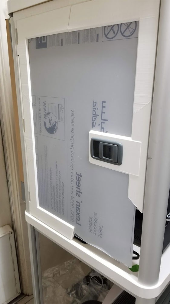
Once the hinge side of the door is assembled, it can be test fit in the door frame to verify there are no clearance issues. The Latch side of the door should not be assembled until the plexiglass/lexan is cut to size.
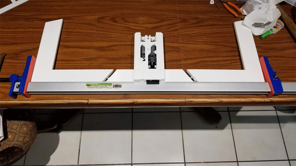
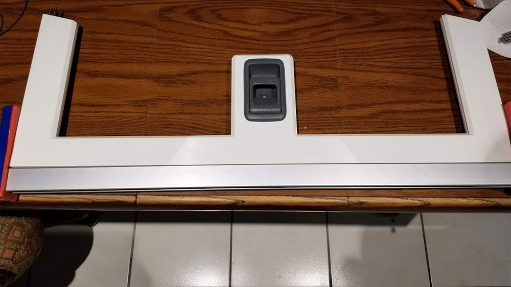
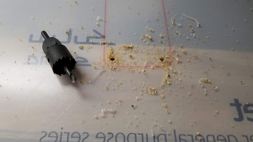
If it looks good, then the polycarbonate sheet needs to be cut out. First cut it to size (approximately 457x665mm for the left side door) - the right side door will be shorter. Once at the correct size, the template can be used to mark where to cut the pocket for the latch. See the pic below for how the template was used. I used some short 5mm dowel pins to help with the alignment of the template.
If it looks good, then the polycarbonate sheet needs to be cut out. First cut it to size (approximately 457x665mm for the left side door) - the right side door will be shorter. Once at the correct size, the template can be used to mark where to cut the pocket for the latch. See the pic below for how the template was used. I used some short 5mm dowel pins to help with the alignment of the template.
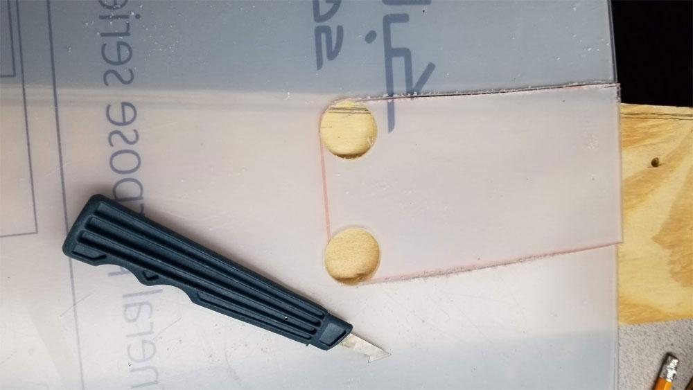
Once the pattern is traced onto the polycarbonate sheet, it can be cut out. I used a hacksaw, drill, and a plexiglass cutting tool which was only used for the part which I could not reach with the hacksaw. I used a drill to create the radius in the corners (sorry I missed the size, but it is a 10mm radius / 20mm diameter). This hole does not need to be perfect since there is a bit of overlap which will cover it.
|
|
Now that the clear sheet is cut, the latch side of the door can be assembled in the same way as the hinge side was assembled. Prior to assembling the latch side though, I took the opportunity to test fit the door in the frame.
If it looks good, then the hinge side and latch side of the door can be assembled. I first installed the 50-60mm pins on one side only, these were glued in with superglue.
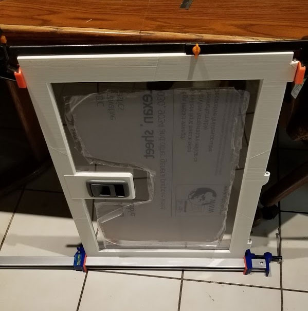
To bring the halves together I used only Clear Gorilla Glue, instead of the superglue, in order to get more working time. I peeled back the masking on the clear sheet, around the edges and added the glue in the grooves it will go into, being careful to not use too much that it would ooze out. I also added glue to the mating surfaces and pins between the hinge and latch side parts. The sides were then brought together and clamps were used at the top and bottom to bring the parts together. The door was allowed to dry completely before removing the clamps.
To bring the halves together I used only Clear Gorilla Glue, instead of the superglue, in order to get more working time. I peeled back the masking on the clear sheet, around the edges and added the glue in the grooves it will go into, being careful to not use too much that it would ooze out. I also added glue to the mating surfaces and pins between the hinge and latch side parts. The sides were then brought together and clamps were used at the top and bottom to bring the parts together. The door was allowed to dry completely before removing the clamps.
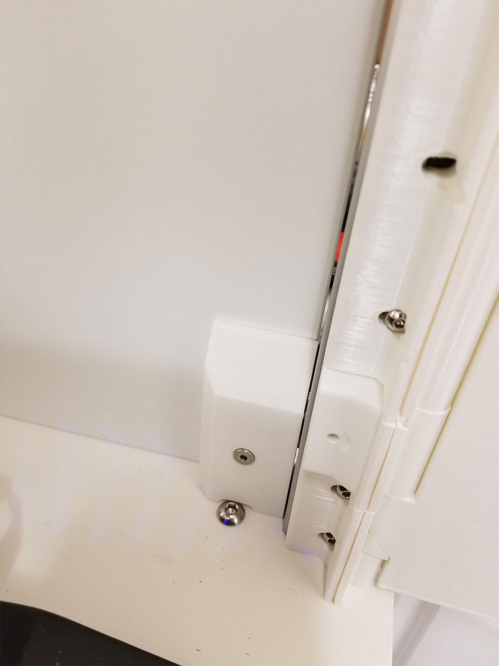
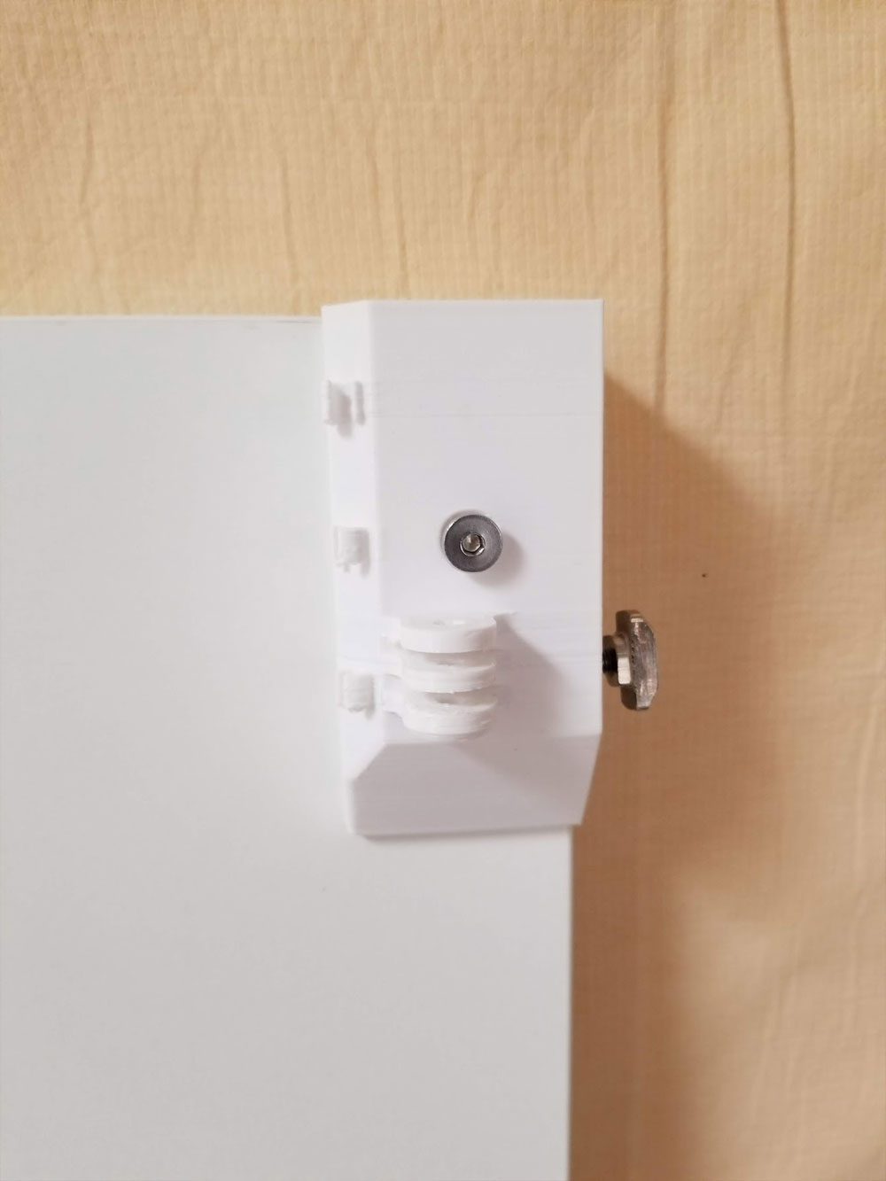
Once the door is glued up, the wedge shaped inserts need to be installed on the hinge side. These are glued in using superglue and the 60mm x 5mm steel dowel pins. The pins need to extend about 10mm below the hinges, to allow the door to be lifted off the hinge when it needs to be installed or removed.
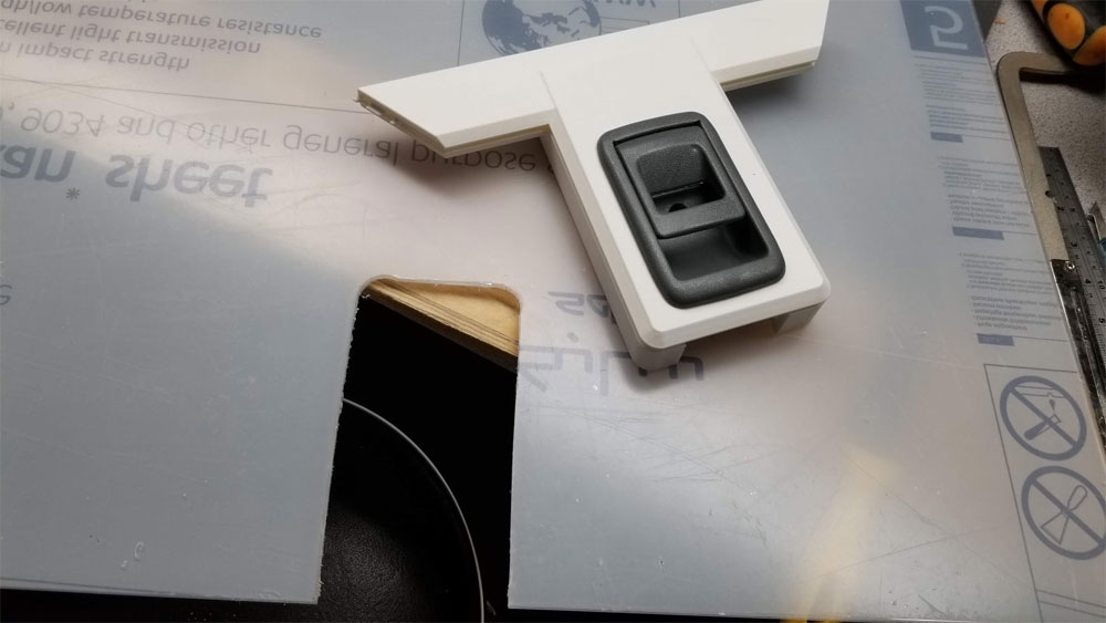
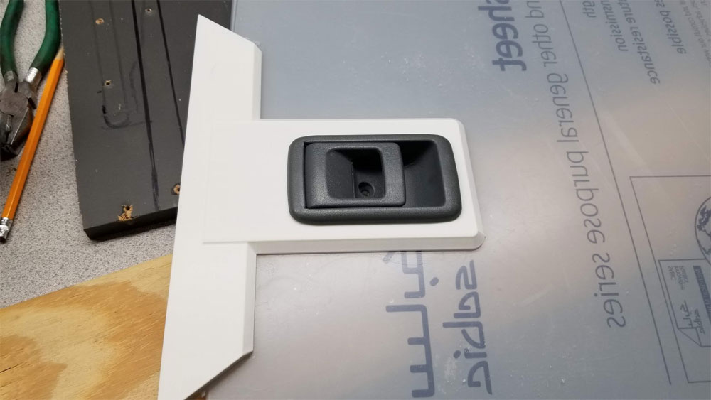
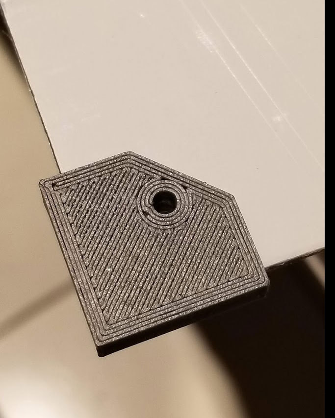
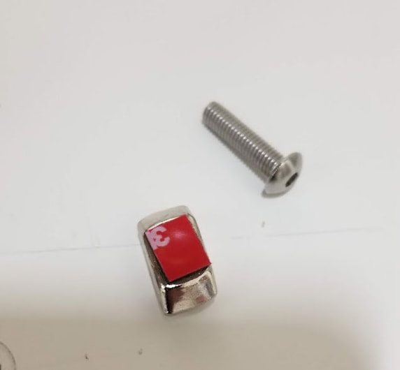
Additionally, two covers need to be installed on the latch. The back cover is held with four M4 nuts and M4x16 to 20mm screws. There is also a small cover which covers the hole that was used to install the pin inside the latching mechanism. This is installed with an M3 insert and M3x10 to 16mm screw.
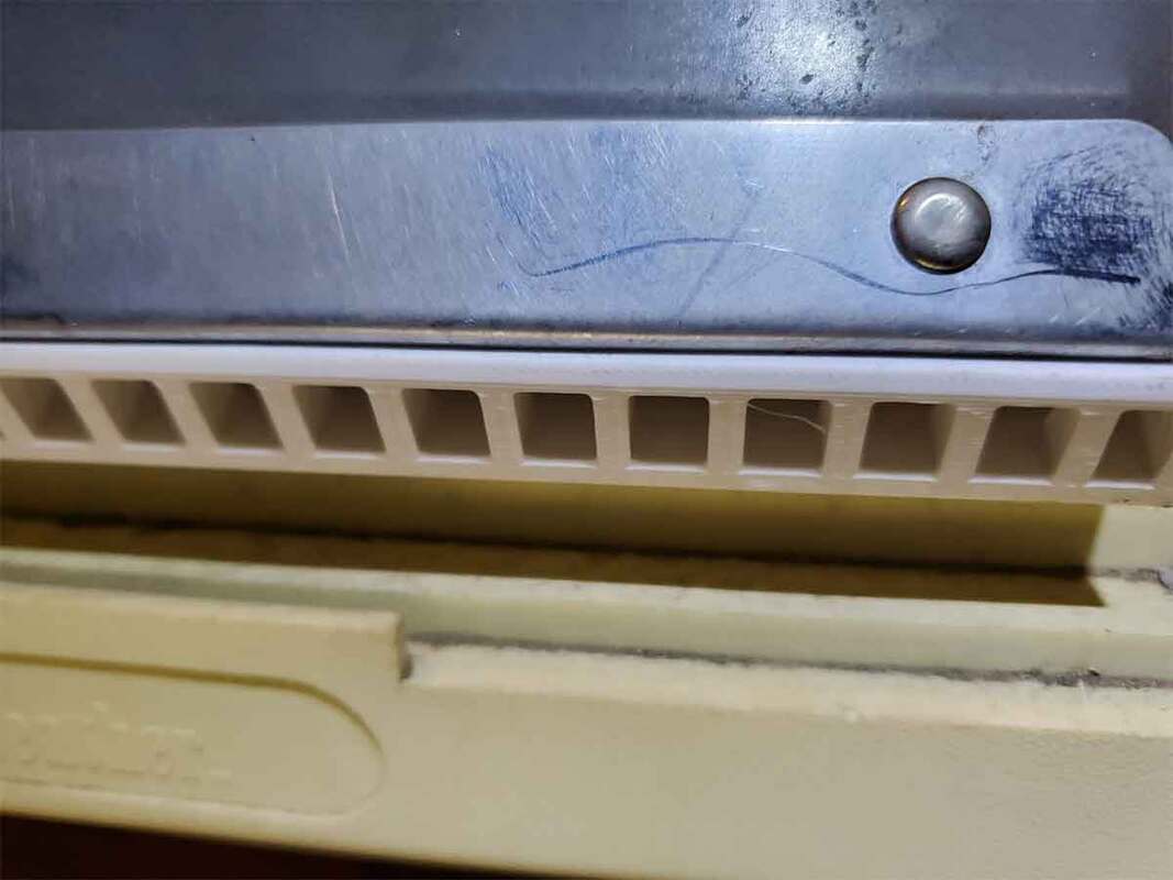
The door frame was designed to be sealed using the rubber weatherstripping (seems the link no longer works but it was white 11/32 Inch Wide X 5/32 Inch Thick silicone weatherstripping). The weather stripping will go around the left, top and right sides of the frame. It can also be added to the bottom of the door.
Additionally, two covers need to be installed on the latch. The back cover is held with four M4 nuts and M4x16 to 20mm screws. There is also a small cover which covers the hole that was used to install the pin inside the latching mechanism. This is installed with an M3 insert and M3x10 to 16mm screw.
The door frame was designed to be sealed using the rubber weatherstripping (seems the link no longer works but it was white 11/32 Inch Wide X 5/32 Inch Thick silicone weatherstripping). The weather stripping will go around the left, top and right sides of the frame. It can also be added to the bottom of the door.
Back Shell
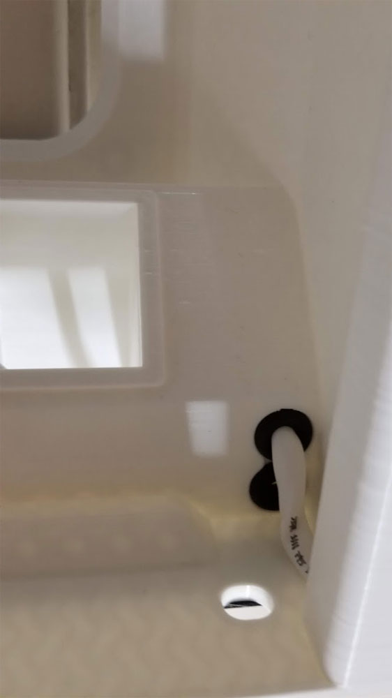
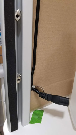
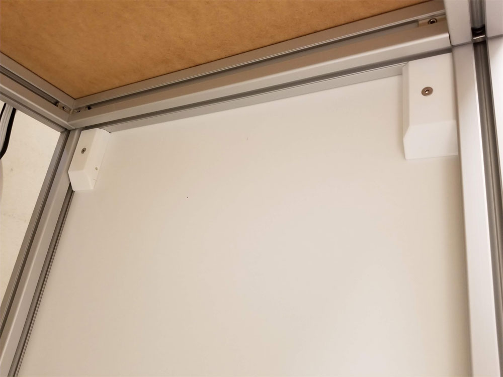
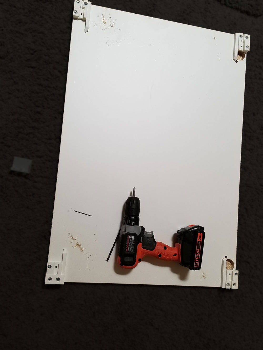
The back shell is needed since the CR10 is a bit too big to fit at full throw, on the footprint of the Ikea "Tingby" table top. It bumps out to accommodate the space needed and also includes a power and USB outlet, tool holder and filtered air inlet (or exhaust port). The back shell is a printed frame with an 18" x 24" 3mm aluminum composite panel which makes up the back. The printed frame is glued and pinned similar to the doors (using 5mmx60mm steel dowel pins). The back shell is held in by M5x16mm button head screws with M5 T-nuts in the 4545 extrusions on the top and sides, and by four M8x50mm button head screws on the bottom, which go though the Tingby top, into captive T-nut's in an extrusion below. Getting the T-nuts to align with everything is tricky, but since I had already built the frame of the cabinet, and did not want to take it apart to slide in the t-nuts (and there was no clearance to install them otherwise), I used a method with 3M VHB tape to set them in place and then install the screws later, during final assembly (pics below). In hindsight, I could have used roll in T-nuts similar to these.
I did run into some snags with the back shell which I need to fix. One problem was the cable management channel, which was a bit small, so I will need to make it larger along the side. It is also pretty difficult to feed the wire through the cable channel when the grommet is installed, not sure what the fix there will be. Finally the holes for the M8 bolts were mis-placed on my parts, which is a simple fix, but not worth re-printing the back shell for (which represents about 5 or 6 days of printing and a couple spools of PLA). I also modified the exhaust fan design to make it a bit easier to mount, though it is still not as simple as I would like (though not super difficult either).
I pre-ran the wires in the back shell since I knew the cable management would not be ideal, and getting the cables in later would be very frustrating so I took the time to feed the wires through first.


To fix the T-nuts in the 4545 extrusions I used some VHB tape on the backs of the nuts, then set them in place using a longer M5 screw and pressed them into the groove. I usually tried to set them so they would be perpendicular to the slot, but the important thing is that they were aligned with the marks I made using the holes in the back shell (so when I install it, the screws will be in line with the nuts). This worked really well and I did not miss a single T-nut. A simpler method would be to use the roll in type T-nuts which have a spring to hold them in place.
|
|
Before I installed the back shell, I used some 1mm neoprene tape to seal around it (applied to the frame on the top and sides, and to the back shell on the bottom. The fit was very tight so the 1mm tape was plenty thick to seal it up, and when the screws were tightened down it all seemed very solid.
Some M6 hardware was used to install the 18"x24" 3mm thick aluminum composite panel, which I had previously drilled holes in using a printed jig (the gray thing in the 4th pic above). The panel is held on using 4 M6x16mm hex bolts which are inserted into printed knobs. They attach to M6 nuts which are heat set into the back shell. I used more of the 1mm neoprene tape on the aluminum panel, and the back shell frame, which should help make a seal when the screws are tightened down.
Some M6 hardware was used to install the 18"x24" 3mm thick aluminum composite panel, which I had previously drilled holes in using a printed jig (the gray thing in the 4th pic above). The panel is held on using 4 M6x16mm hex bolts which are inserted into printed knobs. They attach to M6 nuts which are heat set into the back shell. I used more of the 1mm neoprene tape on the aluminum panel, and the back shell frame, which should help make a seal when the screws are tightened down.
|
|
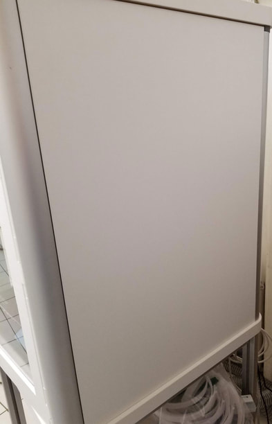
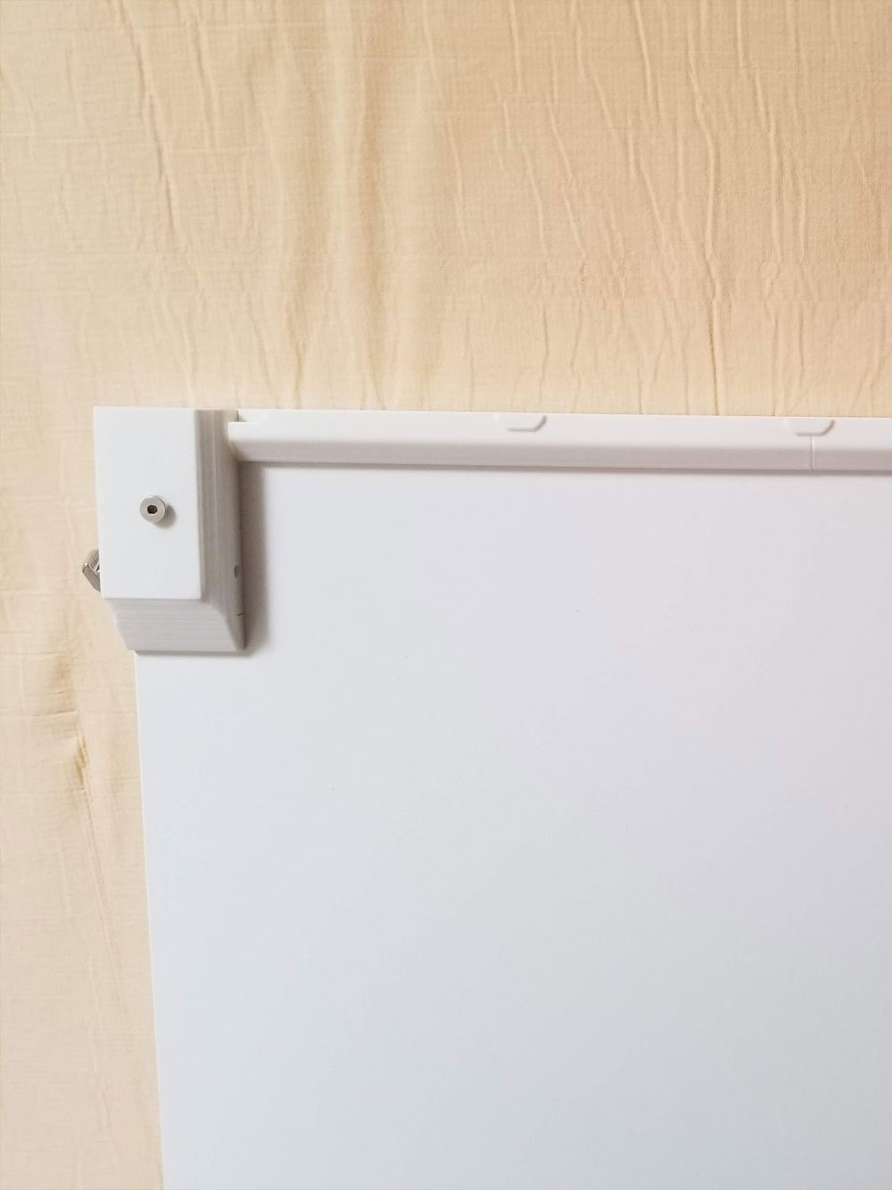
The sides were finally completed recently (July 2020) and I am quite happy with the way they turned out. I used Ikea HÄGGEBY cabinet doors (602.671.81 - now discontinued) and printed some 2 part mounting parts that avoid having any screws showing from the outside. The doors are held in with M5x20mm screws and M5 T-Nuts, so the connection to the frame is very secure. I also had to use some white felt tape around 2 sides of the cabinet doors which helped seal the 1mm or so gap. Due to the tightness of the side panels, I was only able to use the tape on one side and the bottom of the doors before mounting them as the sides of the enclosure. My WebCam finally got installed on the printer too. I made a Go-Pro style mount and ran the cable in a small channel back to the backshell's cable management channels.


After using this for months, it is functionally great, and the doors are smooth and I can just push them closed which is nice. There is an aesthetic problem which I hope will be fixed by a redesign of the way the doors go together. The version I printed relies on glue and 5mm steel dowel pins to hold the doors together and the result is very sturdy. I sometimes catch myself leaning on them but they have never given me a reason to doubt their integrity. However some of that glue got on the surface and has turned yellow. I plan to clean it off but I think a better design would utilize dovetail joints as well as the dowel pins. I'd still use glue, but I think it would be less likely to ooze out to the surface. That new design is done, but not printed.
I am also going to add a drawer to the lower half. I found that an Ikea MAXIMERA 21x24 drawer (602.656.72) and UTRUSTA 21" drawer front (302.656.35) will fit with some printed parts to assist in mounting. The only drawback is that due to the pandemic, Ikea has a month long turn around on shipping. Due to that I did design a printed drawer system, buy when I sliced it, found the print time would be over 2 weeks (oof). The cost of the printed system would be about 1.5x more than just buying and waiting for the Ikea drawer too, so I went with the Ikea option. With a drawer in the lower section, I would still have the ability to put the Ender3 down there, and would probably need to design a static roof for that section so I could mount lights and other items below the drawer.
(Updated 10/1/2022) On the next version I'm considering adding some integrated sensor options to the enclosure parts, including the following:
- Door sensors integrated into the printed doors and jams.
- Temp and Humidity sensors, probably integrated into the backshell.
- Smoke sensors.
- Need to design a small mount for the PM2.5 sensor which I have just sitting in the enclosure currently.
- Design and install a compartment for a 12v or 5V supply, fuse block and controllers for the lighting, fans and sensors. I posted a candidate design for that here, but I am not really happy with that design for this enclosure and will probably re-design it to integrate into the lower backshell.
- Install the 5" Raspberry Pi Touchscreen and figure out the cable management for it (design is completed but not tested).
|
|
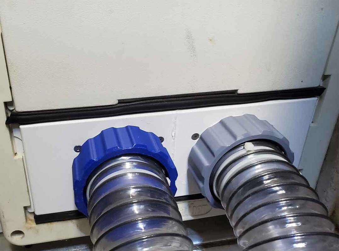
Doggie Door Pass Through for the Vent
Pardon the dust, this has been in use for some time and I only just today took some pics (after months of use). The setup is working great, although I really should shorten the hose which is way too long. The design has couplers at both ends of the hose, one connects to the exhaust from the enclosure (which is run through a prefilter) and the other end goes out through the doggie door via a printed insert. There is a duct on the other side of the doggie door insert which has a duct to exhaust the air just under the flap with some flappers to avoid critters from crawling into the hose from outside (the flappers are not fully tested however). There is no place for critters to go however and there is a grate which will keep anything larger than a very small lizard or bug from crawling into the hose, in several months of use it has not happened so I don't think it's appealing. There is some foam insulation inside the doggie door (in the space between the inside panel and outside, but it is not fully sealed up yet.
|
|
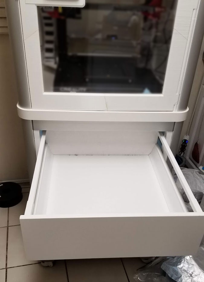
Ikea Drawer for the Enclosure
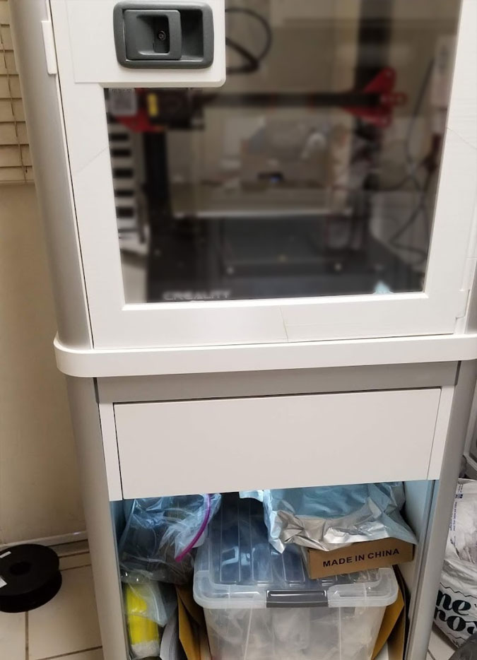
Bless this mess...
|
|
A drawer was added, see this blog post for more details.
