Instructions for the Air Scrubber
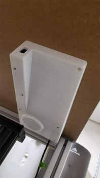
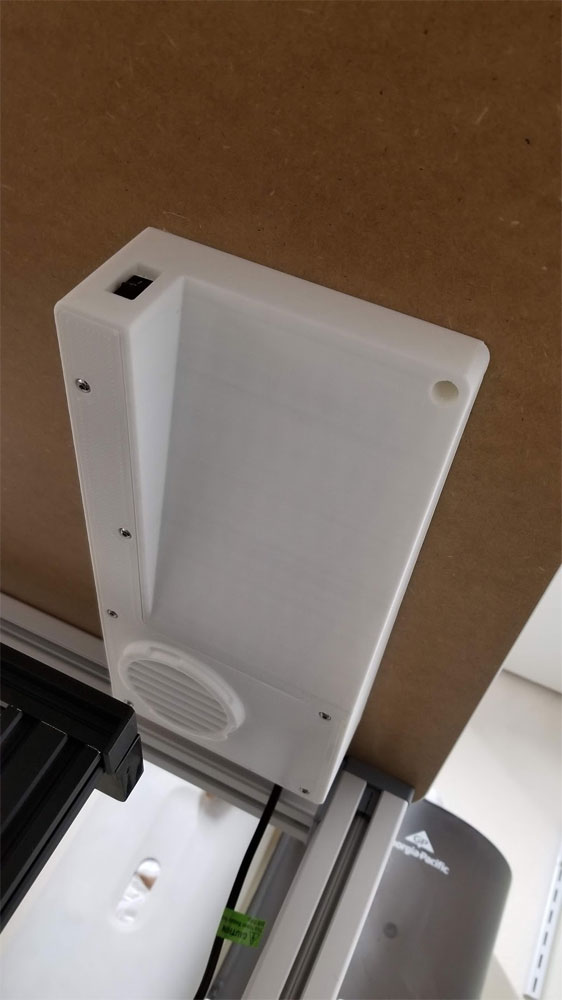
These are instructions for the assembly of the Air Scrubber I am using on my enclosure (which is still a work in progress). The original idea for the scrubber was to arrange the elements to flow from dirty > fan > carbon > HEPA > exhaust. I have zero qualifications for designing a filter so this is strictly an at your own risk deal, and I make no guarantees on if it will work in whatever application it may be used in. I am still testing mine and it does seem to be working, though I have no way to really check for leaks or other issues aside from by feeling around the obvious places they could occur. Additionally I have made several updates and fixes to the design since I printed mine, and do not plan to waste the PLA to print it again to test - though I have test printed some of the parts to verify things like the fit of the fuse holder in the new design.
This was originally intended to use PWM to control the fan (which is 4 wire) but after running it off 12V I found it is just about where I would set it anyway and so will not be messing with PWM control most likely. I have it connected to a 12v 3A supply and from prior testing it pulls less than an amp and is not obnoxiously loud. I added a 2A fuse on the earlier version pictured (which I am running), and my updated model has the fuse integrated in the design using the same fuse holder used on the earlier design - which is available at thingiverse - it was posted there by sk8rjess and originally created by Erik Cederberg (https://www.youmagine.com/meduza) and made available under the Creative Commons Share Alike License.
So on to the fun. This is a long print and a bit complicated build which involves cutting a big hole in the top of the enclosure... so measure a few times and cut once. I designed this with a template to set the side of the scrubber 54.5mm in from the edge of the top of the enclosure (just keep that in mind since it may need to be adjusted for the application).
Some other things to note about this design and build:
Bill of Materials:
Build it:
This was originally intended to use PWM to control the fan (which is 4 wire) but after running it off 12V I found it is just about where I would set it anyway and so will not be messing with PWM control most likely. I have it connected to a 12v 3A supply and from prior testing it pulls less than an amp and is not obnoxiously loud. I added a 2A fuse on the earlier version pictured (which I am running), and my updated model has the fuse integrated in the design using the same fuse holder used on the earlier design - which is available at thingiverse - it was posted there by sk8rjess and originally created by Erik Cederberg (https://www.youmagine.com/meduza) and made available under the Creative Commons Share Alike License.
So on to the fun. This is a long print and a bit complicated build which involves cutting a big hole in the top of the enclosure... so measure a few times and cut once. I designed this with a template to set the side of the scrubber 54.5mm in from the edge of the top of the enclosure (just keep that in mind since it may need to be adjusted for the application).
Some other things to note about this design and build:
- I found that I needed some longer M4 flat head screws than I thought, I think they were M4x45mm (50mm should also work) flat head screws. I also used a chamfering bit to chamfer the hole on the fan itself so the heads of the screws would not bump the lid. That is hopefully resolved with some relief holes added to the lid to accommodate the fan mounting screws - but if that is a problem, a small chamfer on the fan should make them fit.
- The switch on the design shown was also loose, so I tightened up the hole a bit, it may still require some glue if it bothers you (mine did not even though a bit loose in assembly, it is not noticeable in operation).
- The template is designed to use on the bottom side of the top of the enclosure first, so I used it there, drilled and cut the bottom side holes, and then used some holes drilled up through from the bottom to help align the template to the top side.
- The bolsters are designed to go inside the top and give the #8 wood screws something to bite into and give some strength to the hollow table top. To get them in place I drilled some additional holes from the bottom (which are used only for the top) which allowed me to align the bolsters before drilling the pilot holes from below which helped align the gig for cutting the top holes.
Bill of Materials:
- #8 7/8" wood screws (a dozen should do it)
- M4 x 45mm (or 50mm) flat head screws (2 for mounting the fan)
- M3 x25-45mm round or flat head screws (6 for securing the lid)
- M3 x20mm round or flat head screws (5 for the carbon filter)
- M3 x10mm round or cap head screws (4 for mounting the filter grill)
- M3 x12mm round head screw (2 for mounting the fuse holder)
- M3 4mm x 4.3mm brass inserts (qty 5, get some extras though) for the carbon filter)
https://www.amazon.com/Uxcell-a16041800ux0833-Knurled-Threaded-Embedded/dp/B01IYWUUH8/ - M3 nuts (20)
- M4 nuts (6)
- Wire, I think I used 18 or 20 gauge
- Fuse (I used a 2Amp standard fuse but use your best judgement)
- 1x DC 2.1x5.5mm panel connectors, these can be found cheaper on Ebay (1) - THIS NEEDS TO BE COMPATIBLE WITH THE SIZE USED ON THE POWER SUPPLY CONNECTOR (2.5mmx5.5mm is the other size that I have used in the past).
- Rocker switch (I used the smaller AC 250V/3A 125V/6A versions in this assortment)
- Delta BFB1012VH fan (I bought it at Amazon but seems the link has changed since - no prime but it is cheaper) - note that red is +12V and black is ground, the pins are not in the standard 4 wire arrangement so don't connect this to a standard 4 wire header without checking the pinouts.
- HEPA Vacuum Filter for Kenmore EF-1
- 4x8 mesh Activated Carbon from Coconut Shells (from EnviroSupply) The 1 Lb bag should last a long time, but it needs to be washed with RO or distilled water to remove the dust (and then I just dried it outside in a veggie bag for a few hours).
- 1mm thick Black EVA Foam Tape (single sided) 15mm x 10M I think 2mm thick x 10mm will also work and may be cheaper.
- A 12V power supply with the correct connector to run the fan - I would get one that can provide at least 3 Amps.
Build it:
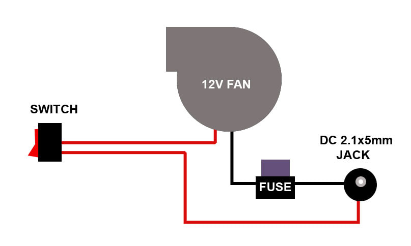
- First, assemble the scrubber and test it out to make sure it works. I would not cut any wires if possible for this test since if it does not work you may need to return the fan (some sellers will sell used system pulled fans as new, so it is worth testing it beforehand). The wiring is simple and I placed my fuse on the negative side since the case is plastic and nothing is otherwise grounded, but best practice is to put the fuse on the red (+12V side). It can be done either way, below is just an example and shows how I did it on mine. UPDATE - This works, but not well for my power supply and fan. I am going to re-do this diagram and the circuit on my fan, since I want to add an external flyback diode, and a capacitor to smooth the current going to the fan.
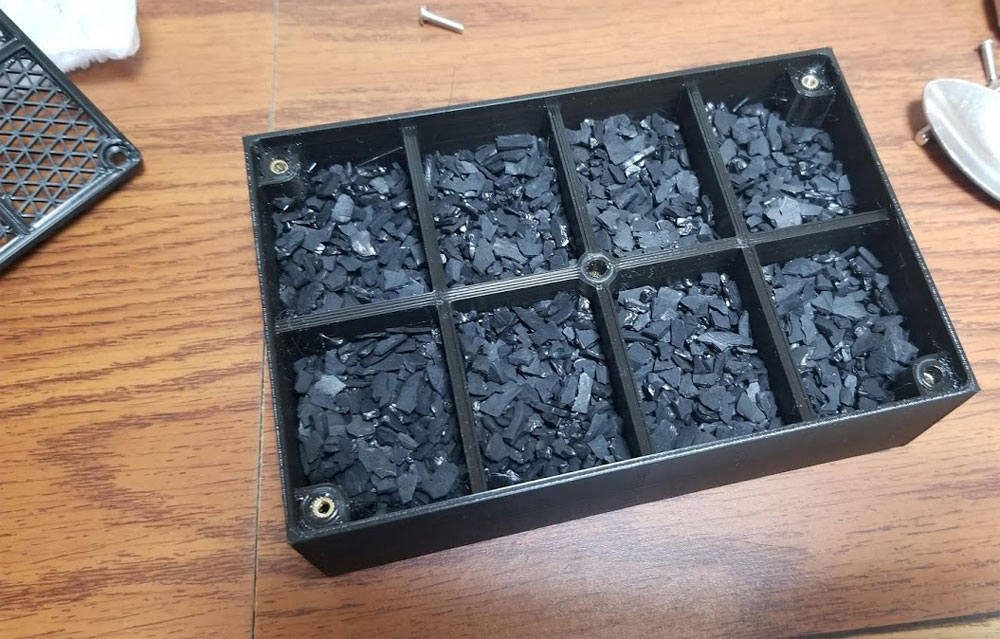
2. If everything works, the next step is to assemble the carbon filter box. This requires the M3 inserts, and they go into the base. I just thread them on a few mm onto a screw and then heat em with a lighter and press them in. The activated carbon then goes in and I filled mine a bit over 3/4 but I think it could be filled full without much air flow restriction.
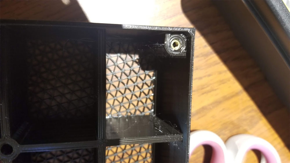
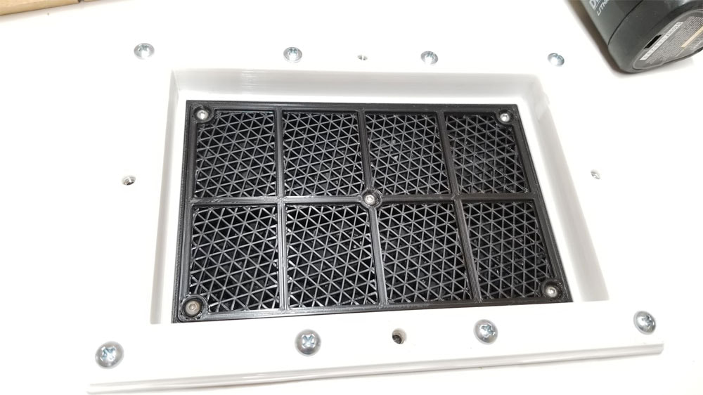
The grate pattern on the box was printed as infill only in Cura in case you are curious. I will make another write up on how that was done, but in a nutshell, it was 2 parts; the box and a 2nd part for the grates. Cura was set up to print the parts together, but with different settings, so the grating was done with zero top or bottom layers, no walls and it used triangle infill IRRC.
The grate pattern on the box was printed as infill only in Cura in case you are curious. I will make another write up on how that was done, but in a nutshell, it was 2 parts; the box and a 2nd part for the grates. Cura was set up to print the parts together, but with different settings, so the grating was done with zero top or bottom layers, no walls and it used triangle infill IRRC.
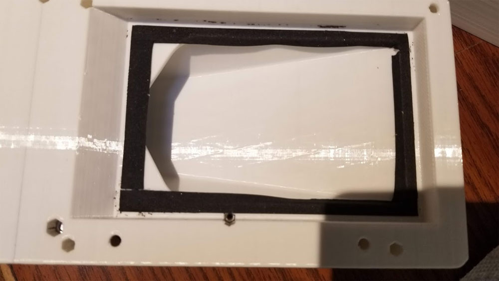
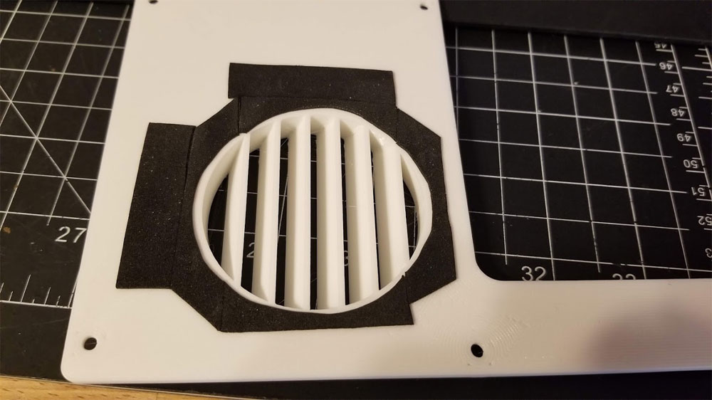
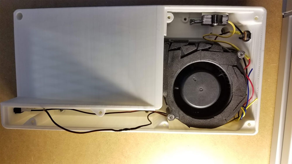
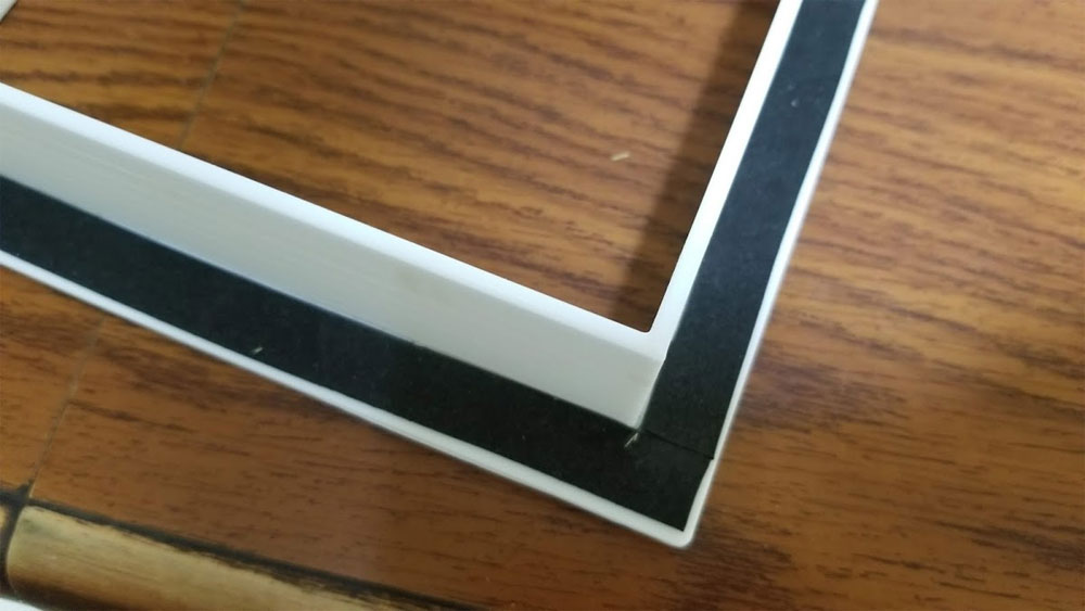
3. I would recommend using the 1mm thick EVA foam tape to create a better seal on the following parts - see the pics below. Clockwise from the top left:
- This is inside of the base where the carbon filter will sit. I would recommend installing the tape after gluing in the insert which holds the carbon filter (not shown in the pic - see step 4 below), but either way, the foam tape should not be put where it will be under the insert (which is why there is about a 2-3mm gap around the edges in the pic).
- Around the fan outlet, I went around once and then around the top and sides of the fan one more time (top being the side with the opening, not the label side).
- I also added some foam tape to the top of the fan where it would seal against the lid of the case.
- Hard to tell from this pic but it is the part that top grill mounts to, and the foam will be between this part and the top of the enclosure when completed.
- On the inside of the lid to help avoid leaks on the intake.
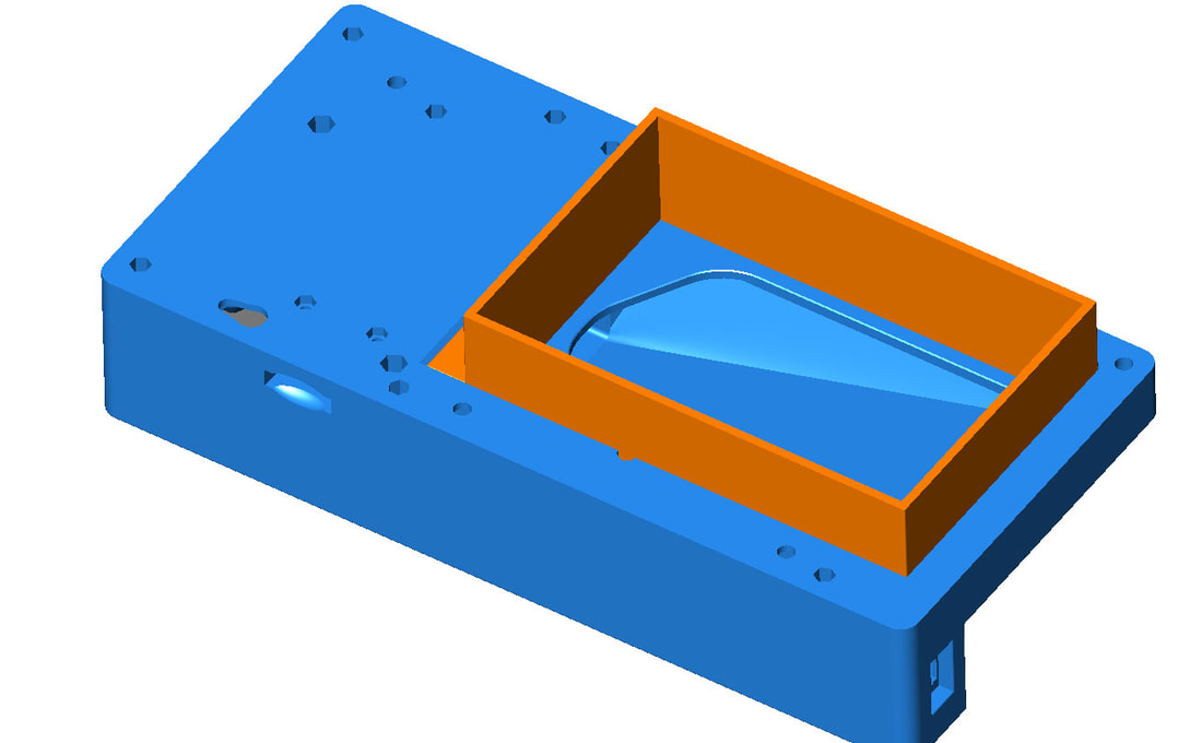
4. Pre-assemble the base to the carbon filter insert. But first verify that the Carbon Filter Box assembed in step 2 fits inside the orange part.
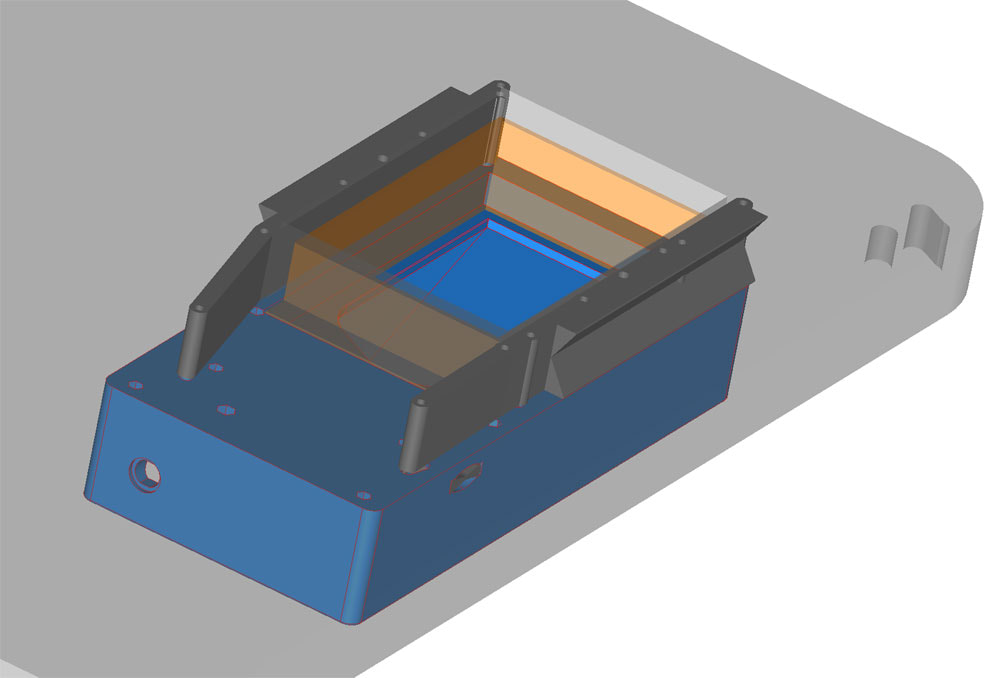
I used some Gorilla Glue to attach these parts (the orange and blue parts in the pic below). Allow them to dry before moving on. In case you are wondering, the reason these parts were separated is to allow printing them without supports.
I used some Gorilla Glue to attach these parts (the orange and blue parts in the pic below). Allow them to dry before moving on. In case you are wondering, the reason these parts were separated is to allow printing them without supports.
5. Now for the moment you have probably been waiting for and I dread writing up. This is again at your own risk, use your judgement and common sense and please don't get upset if I missed something or even (gasp) was wrong about something (but please let me know so I can correct it). Now it's time to cut the damn holes. Before doing any cutting though, double check where you want it to be, and if possible hold it in place with the printer in the enclosure to see if there will be any interference with the printer at the top of the z stroke, and any cables or bowden tubes where they normally would be. One you have settled on the location you will need a few things:
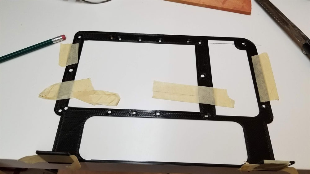
If using the template take a minute to look at which holes go in the bottom and which go into the top. It is much more forgiving to drill holes from the bottom than the top since the bottom side covers more area than the top. The template was designed to be used from the bottom side, since the tabs will help align it when using it from the bottom. It can be used from the top but the tabs do not help there.
I will describe how I used the template (which is set up to put the edge of the scrubber 54.5mm inset from the egde of the table top). Again if your application does not use that same offset then just cut the tabs off or whatever works.
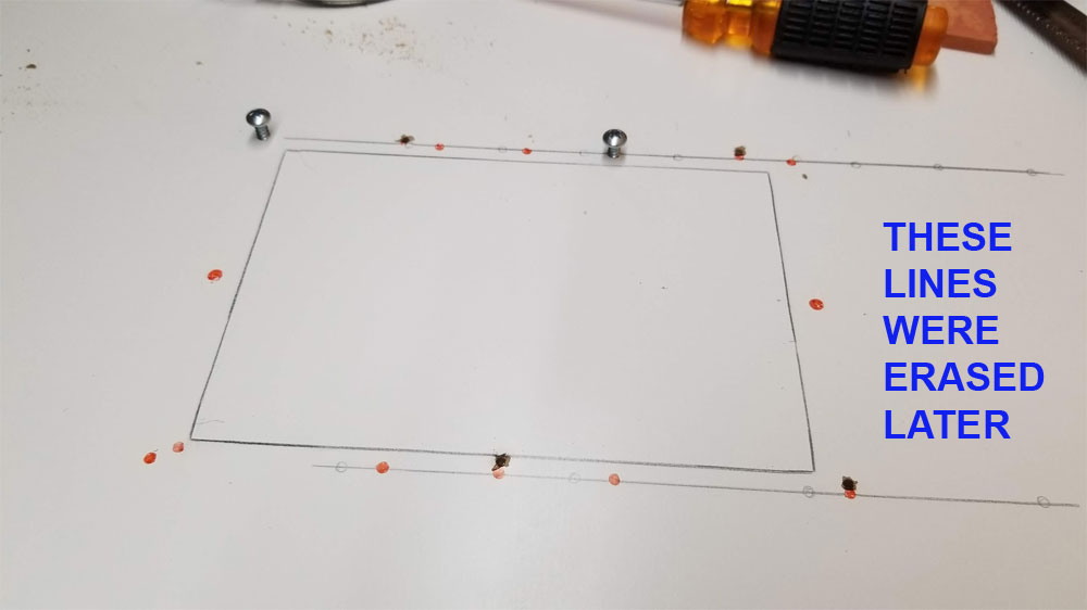
First I mounted the template below the top with tape, and set the base of the scrubber on it one last time to confirm I had clearance for the DC jack to be plugged in and unplugged, and it would not interfere with the sides. Then I marked the holes with a pencil. I did not get a pic of the template in use, but the pic below shows the aftermath (yep I had to readjust it and scoot the opening to the left by about 30mm due to clearance issues).
- pencil
- masking tape
- drill with several size bits, I used a 7/64" bit for the pilot holes
- a straight edge and Vernier Caliper is handy as well.
If using the template take a minute to look at which holes go in the bottom and which go into the top. It is much more forgiving to drill holes from the bottom than the top since the bottom side covers more area than the top. The template was designed to be used from the bottom side, since the tabs will help align it when using it from the bottom. It can be used from the top but the tabs do not help there.
I will describe how I used the template (which is set up to put the edge of the scrubber 54.5mm inset from the egde of the table top). Again if your application does not use that same offset then just cut the tabs off or whatever works.
First I mounted the template below the top with tape, and set the base of the scrubber on it one last time to confirm I had clearance for the DC jack to be plugged in and unplugged, and it would not interfere with the sides. Then I marked the holes with a pencil. I did not get a pic of the template in use, but the pic below shows the aftermath (yep I had to readjust it and scoot the opening to the left by about 30mm due to clearance issues).
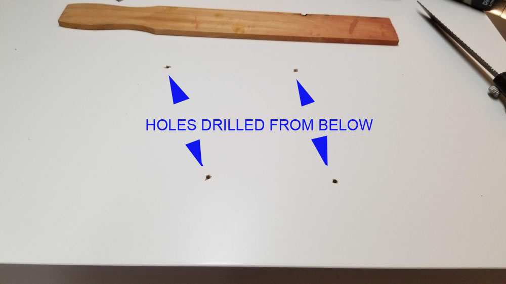
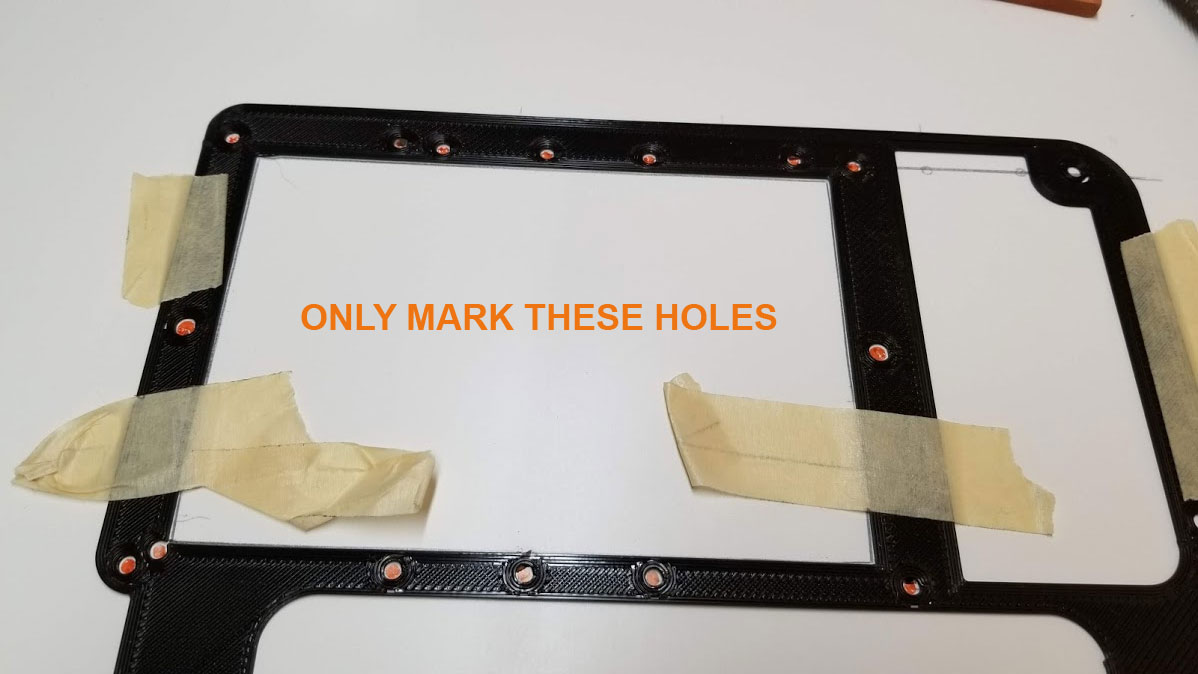
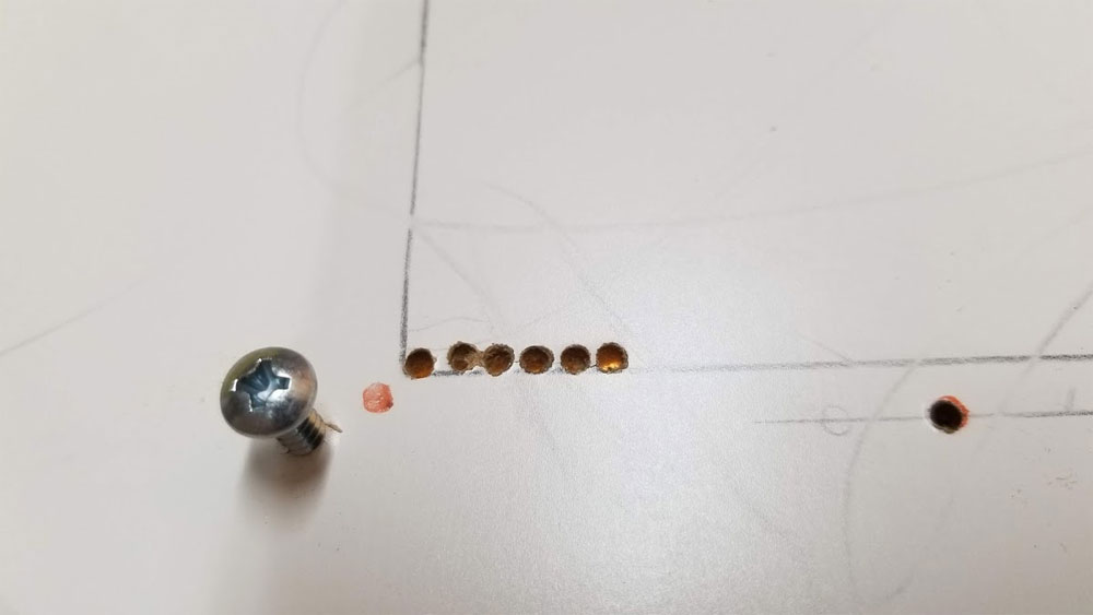
After cutting and drilling the holes in the bottom, I next installed the bolsters. The bolsters help support the scrubber in the hollow Ikea table top, they also give the wood screws something to bite into. You may have noticed in the above pic that I drilled several more holes in the bottom than were necessary. These holes are actually used for the top, but when drilled from below they will be covered up later and for now, they will help align the bolsters and also the pilot holes later - so just drill em all (in the bottom of the Table top that is).
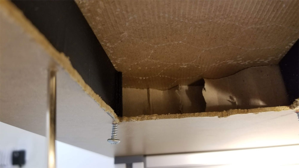
Once the holes are drilled, I installed the bolsters. The bolsters go in though the big square opening and some bushwacking of the cardboard honeycomb may be needed to get then in place. They should not be difficult to get in - if they are, use a caliper or ruler to verify they are not too tall. If they are too short you may be able to shim them. I used some of the extra holes to help align them and then installed screws in the farthest holes before drilling the pilot holes through to the top of the table top. Take special care with the hole on the top left in the pic above. It has 2 screw holes in close proximity, with the hole closest the large opening being used for the scrubber base (bottom side). It is easy to put the screw into the wrong hole at that location. Once the screws were installed as shown above, I felt around the bolsters to verify that they were actually in the correct holes and were not pushing the bolsters up but seated correctly - just mentioning that since this is a bit tricky to get them correctly installed as it is all done blind.
Once the holes are drilled, I installed the bolsters. The bolsters go in though the big square opening and some bushwacking of the cardboard honeycomb may be needed to get then in place. They should not be difficult to get in - if they are, use a caliper or ruler to verify they are not too tall. If they are too short you may be able to shim them. I used some of the extra holes to help align them and then installed screws in the farthest holes before drilling the pilot holes through to the top of the table top. Take special care with the hole on the top left in the pic above. It has 2 screw holes in close proximity, with the hole closest the large opening being used for the scrubber base (bottom side). It is easy to put the screw into the wrong hole at that location. Once the screws were installed as shown above, I felt around the bolsters to verify that they were actually in the correct holes and were not pushing the bolsters up but seated correctly - just mentioning that since this is a bit tricky to get them correctly installed as it is all done blind.
6. Next, some pilot holes need to be drilled through from the bottom through to the top. First make sure the bolsters are as correctly installed and perpendicular to the table as possible. Then, take a look at the top piece and note where the mounting holes are. Make sure to only drill pilot holes in the screw locations that will be used on the top. Using a couple (not more than 4) of the holes which will be used for the top, carefully drill through them from below, using a small 7/64" bit. Note that these holes probably will not land where they need to be, so be careful not to blow out the material on top and only put the minimum number of holes in. I used a block of wood on top to help avoid blowing out the board, but still managed to make the holes look ugly - but fortunately they get covered up later anyway.
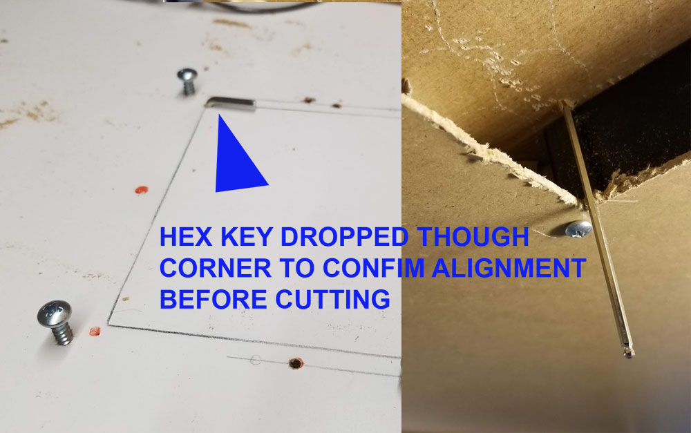
7. Template time again, so go dig it out of the trash. Take note of the orientation of the template, it should be front to back the same as below, with the tabs (if they are still there) facing up this time. Now, those pilot holes are probably going to be a few mm off so, to get it closer to where it needs to be, I measured and re-measured, comparing the locations of the holes as they were on top to where they started out below. My pilot holes ended up about 2mm further in from the edge so I set the template down and used the holes in it to make dots which I connected with lines. The pilot holes were then transposed onto these lines to get the closest point to where they should have landed. Once I was happy, I set the template down and taped it for marking. After drilling some of the holes I put screws in to verify they aligned with the bolsters, then put the remainder of the holes in. For the square hole, I drilled holes in the corners first, and dropped a Hex Key though to confirm it was in the right place.
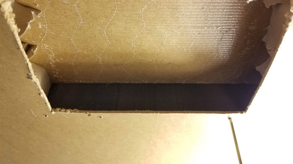
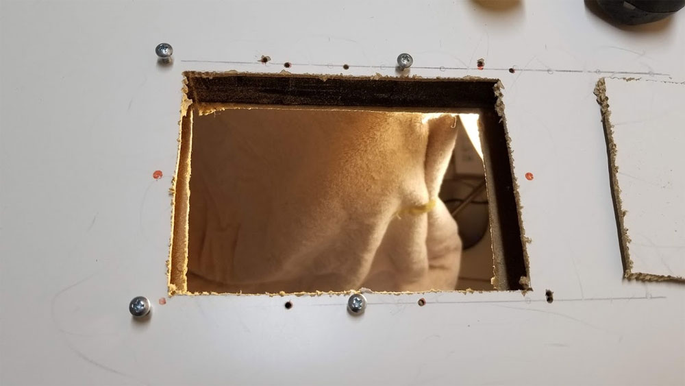
8. Cutting the big rectangular hole in the top was the same as the bottom, but here are some pics from the process. I used a razor and file to clean up the edges.
9. Home stretch, just need to remove the screws from the bottom and mount the base. But first - verify that all the holes in the base which need to have M3 and M4 nuts installed have them (and they did not fall out). Don't want to have to take it all apart later just to put one nut in.
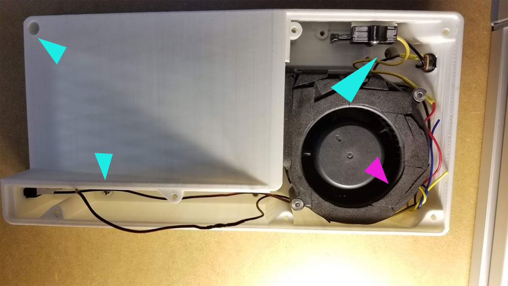
One of the #8 mounting screws is tricky (purple arrow in the pic) and it can not be installed the normal way. Instead this screw, which is under the fan should be screwed into the table top so it protrudes about 5.5mm, it can then go into a keyway in the base which should hold it. Adjust this screw as needed if it seems too tight or loose. Then install the other three #8 wood screws (blue arrows) to hold the base to the bottom of the table top. These screws should all go into the bolsters installed earlier, and it is a good idea to have them held in place with screws from the top while installing the base (so they don't move out of position).
One of the #8 mounting screws is tricky (purple arrow in the pic) and it can not be installed the normal way. Instead this screw, which is under the fan should be screwed into the table top so it protrudes about 5.5mm, it can then go into a keyway in the base which should hold it. Adjust this screw as needed if it seems too tight or loose. Then install the other three #8 wood screws (blue arrows) to hold the base to the bottom of the table top. These screws should all go into the bolsters installed earlier, and it is a good idea to have them held in place with screws from the top while installing the base (so they don't move out of position).
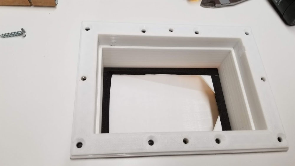
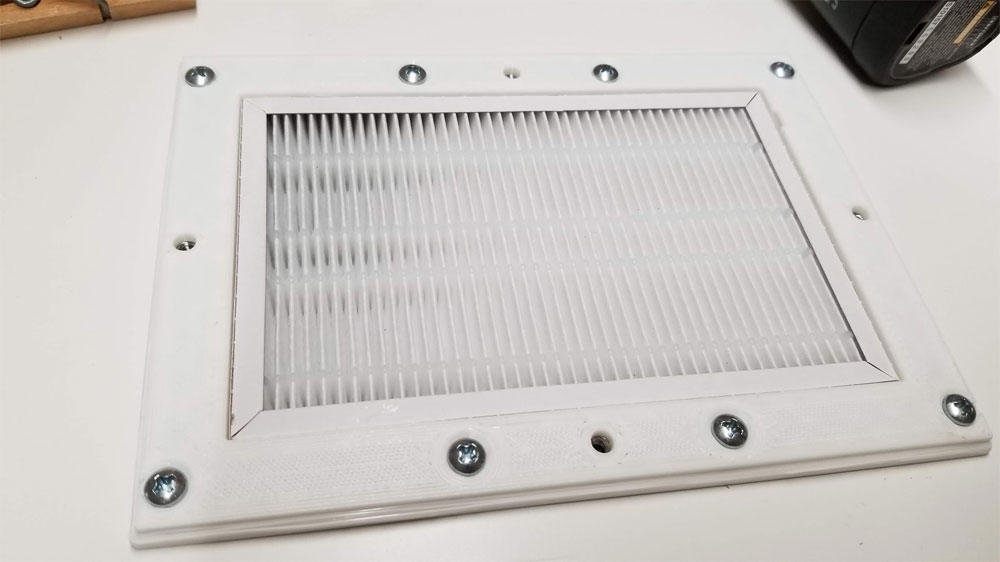
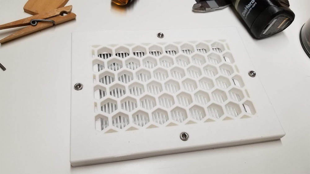
10. Now, going back to the top. I had considered using glue to help seal the top part to the base, but decided against it since the fit was very tight. If a better seal is needed, I'd suggest only using the minimum of sealer (not glue) so that it can be taken apart later if needed. I had to do a bit of minor trimming with a razor blade again to get the top part to slide over the base. Next, verify the four captive M4 nuts are installed in the top, and then it is just putting in the eight #8 wood screws to hold the top, then I dropped the carbon filter in, followed by the HEPA filter and finally the grill which is held by four M4x10mm screws.
11. All that is left is to install the lid using the M3x25-45mm screws. I'd re-check everything before closing it up though.
