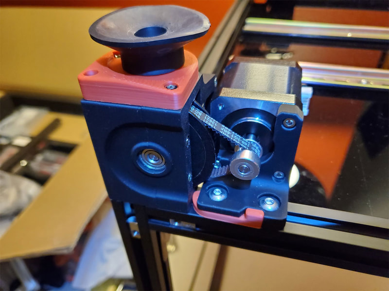
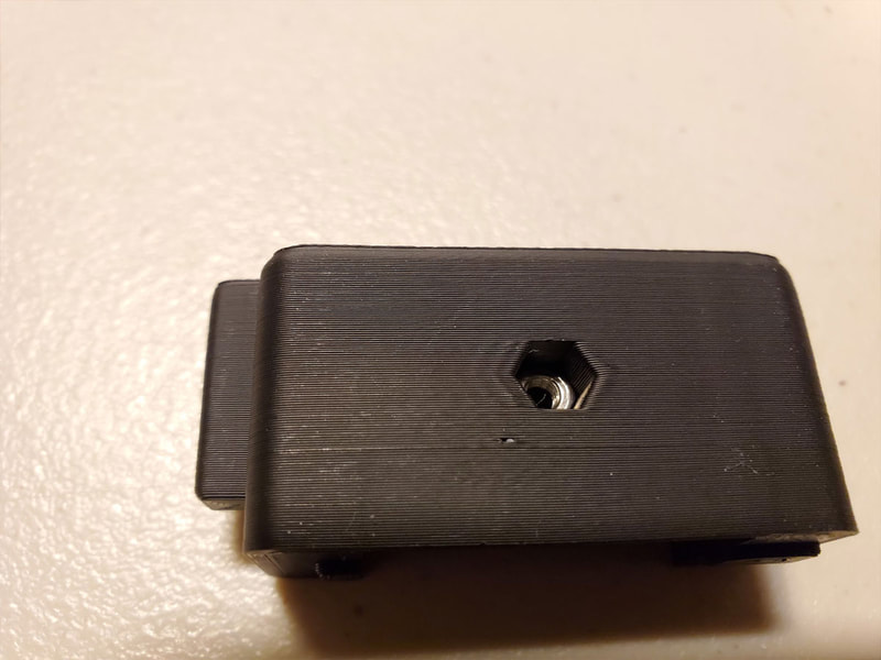
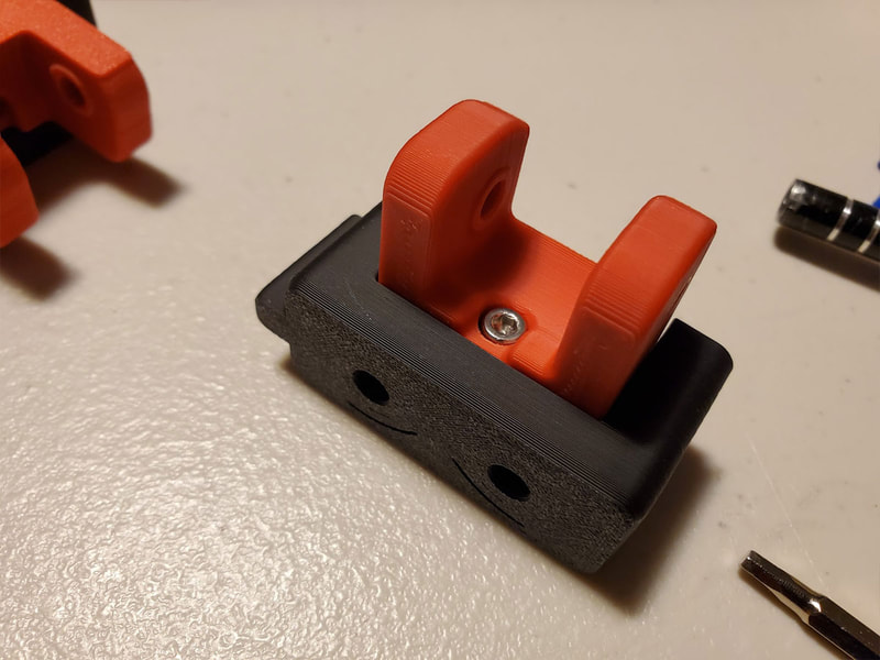
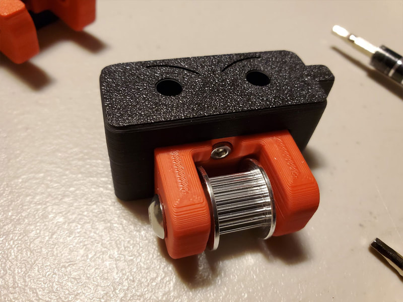
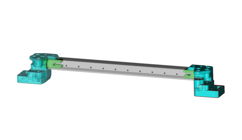
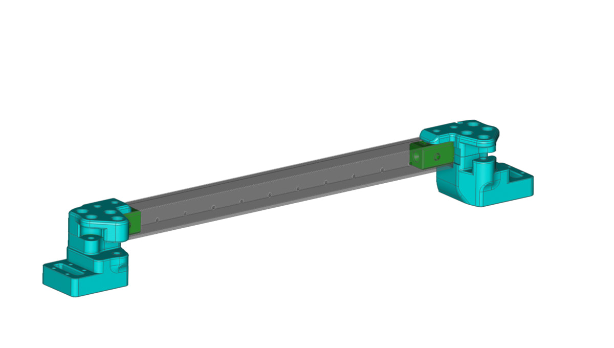
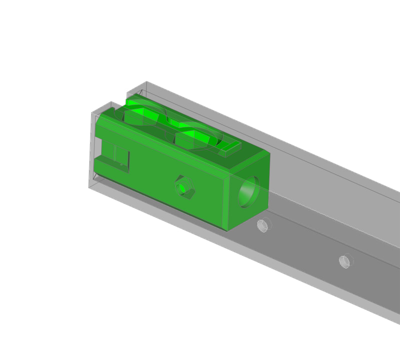
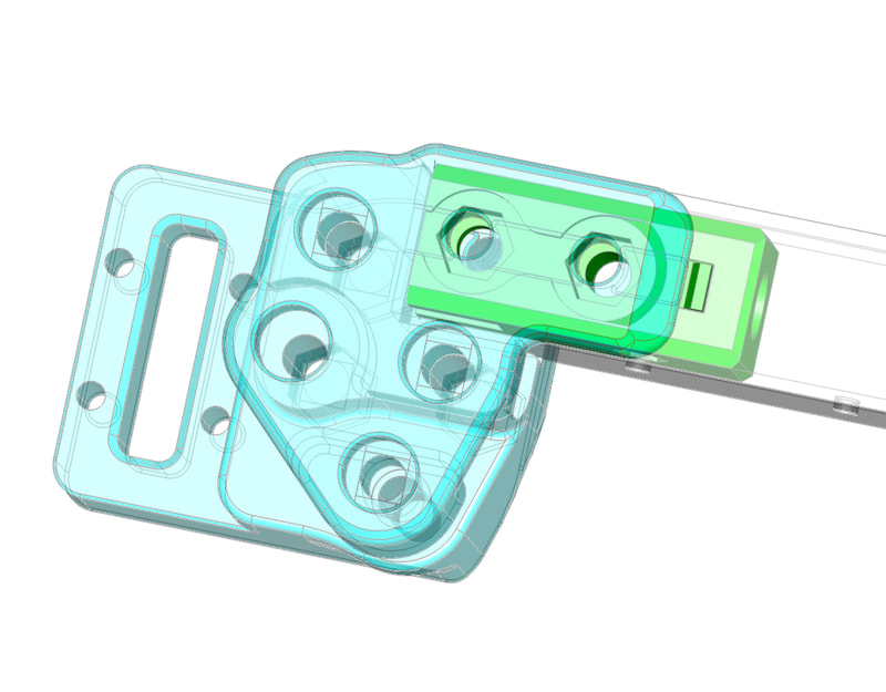
This section will eventually be re-organized, to include some models I'm working on for my Voron 2.4. But for now, it's gonna be where my Voron 2.4 build log will reside.
Voron 2.4 R2 Build Log
This is not gonna be a complete build log (or I'd never get the thing done :D), but I will post some notes and observations here while I work on assembling my Voron R2.4 R1 kit (as an R2). I posted the inventory and general initial observations of the Fysetc V2.4 R2 kit here, and a review of the Maker Panda functional parts kit here.
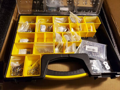
Before starting on a project like this, it will help to organize the hardware and make it accessible. Most of the hardware is M3 and M5, but there is quite a bit of it. I have a few Stanley Organizers so I used one of them to help keep the hardware accessible and in one place. It's clearly not a perfect system, but it has been working pretty well so far. There is nothing labeled but the M5 parts are on the left, then M3 in the center and the other parts are on the right (mostly). I replaced most of the black anodized hardware in the kit with stainless steel, which is why the packaging on the screws is not the same as what shipped with the kit.
Before starting on a project like this, it will help to organize the hardware and make it accessible. Most of the hardware is M3 and M5, but there is quite a bit of it. I have a few Stanley Organizers so I used one of them to help keep the hardware accessible and in one place. It's clearly not a perfect system, but it has been working pretty well so far. There is nothing labeled but the M5 parts are on the left, then M3 in the center and the other parts are on the right (mostly). I replaced most of the black anodized hardware in the kit with stainless steel, which is why the packaging on the screws is not the same as what shipped with the kit.
Primary Resources Used:
The Voron 2.4 manual here.
Nero3D's Youtube Channel (you can find answers to just about any Voron questions in his videos)
Nero3D's Youtube Channel (you can find answers to just about any Voron questions in his videos)
Step 1 (or so) - The Frame
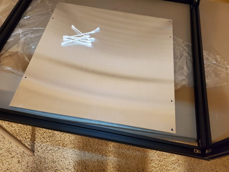
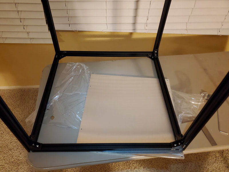
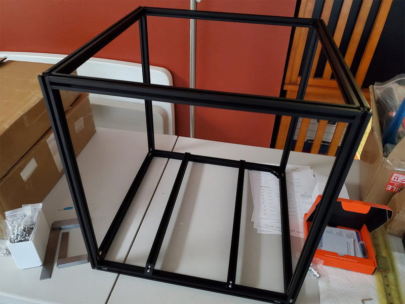
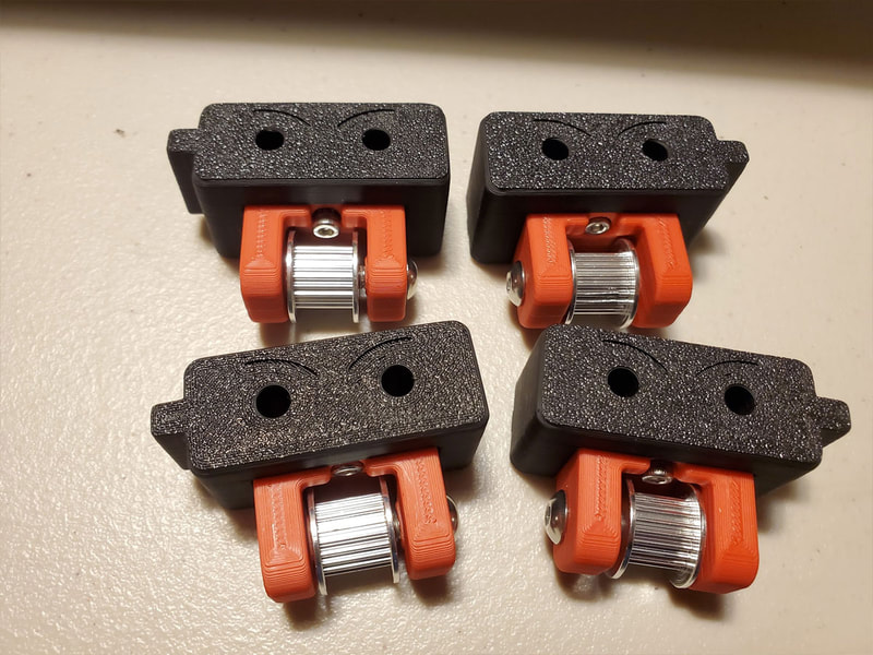
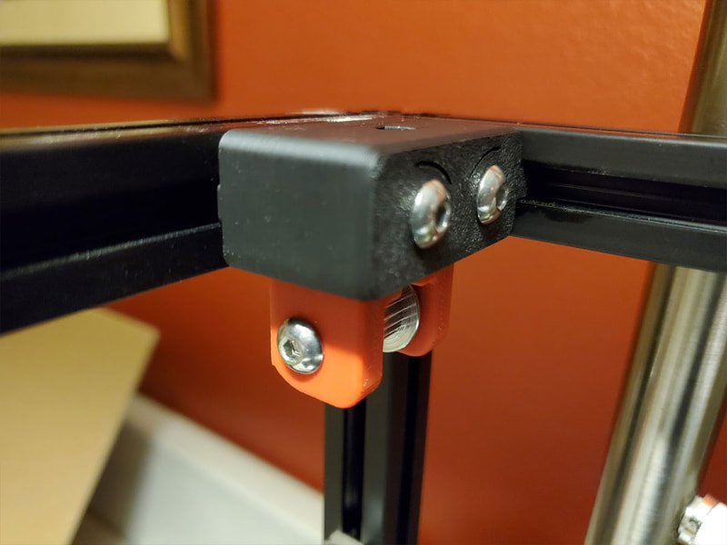
The frame has been the one thing that I was not looking forward to assembling. I did not do much research, but what I did do had me convinced it was gonna be a problem if I did not have a granite surface plate, or a big enough granite counter top to assemble the printer on... I don't have those things, so I used the next best thing, a wobbly card table. I won't suggest it, but it did work, in combination with the aluminum bed, which I used to get an actual flat surface to work with. I also printed a few of these to use during assembly to help hold the newly screwed together corners in place but those were not really necessary in the end. Even with being careful in assembling the corners, my first result was not fantastic.
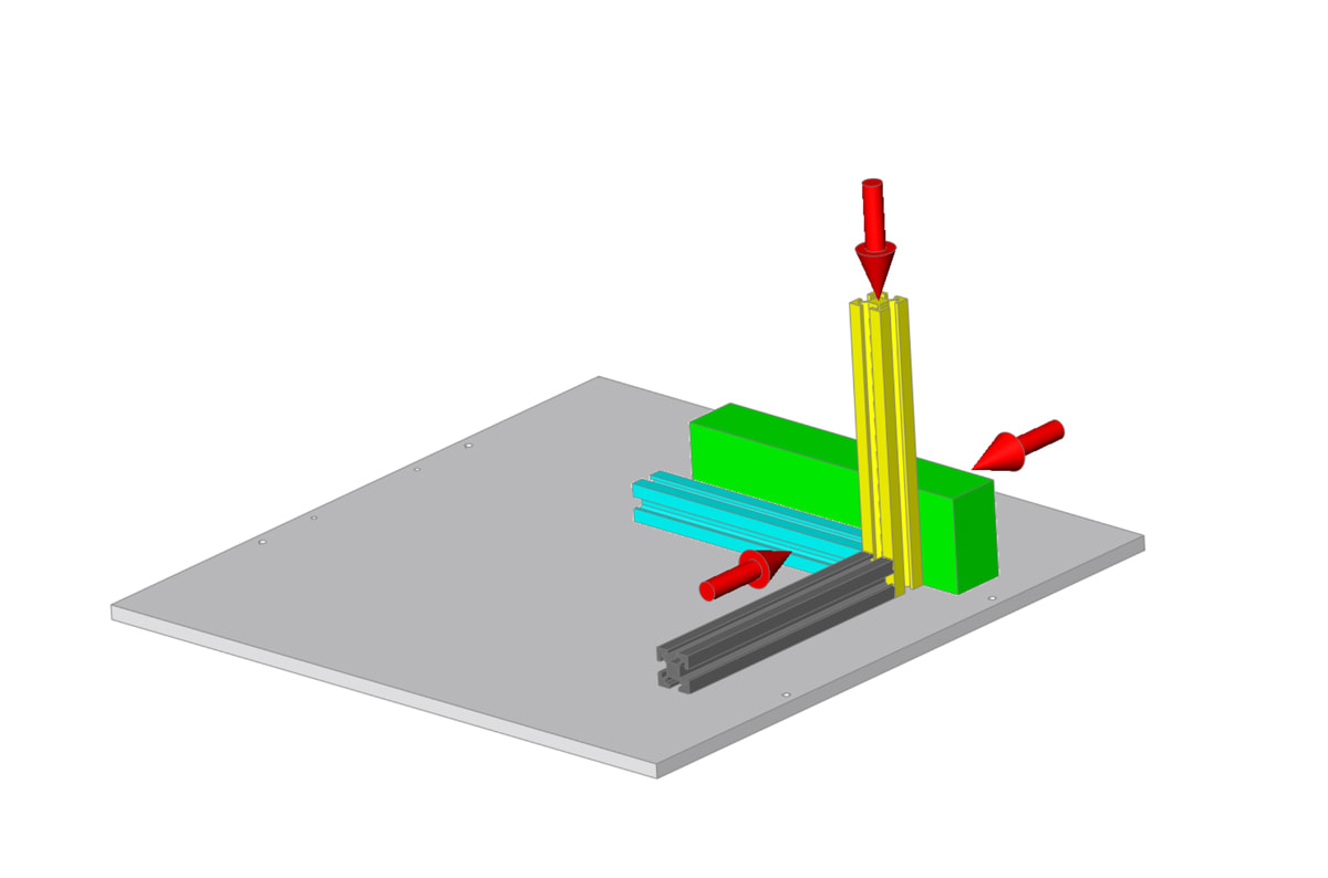
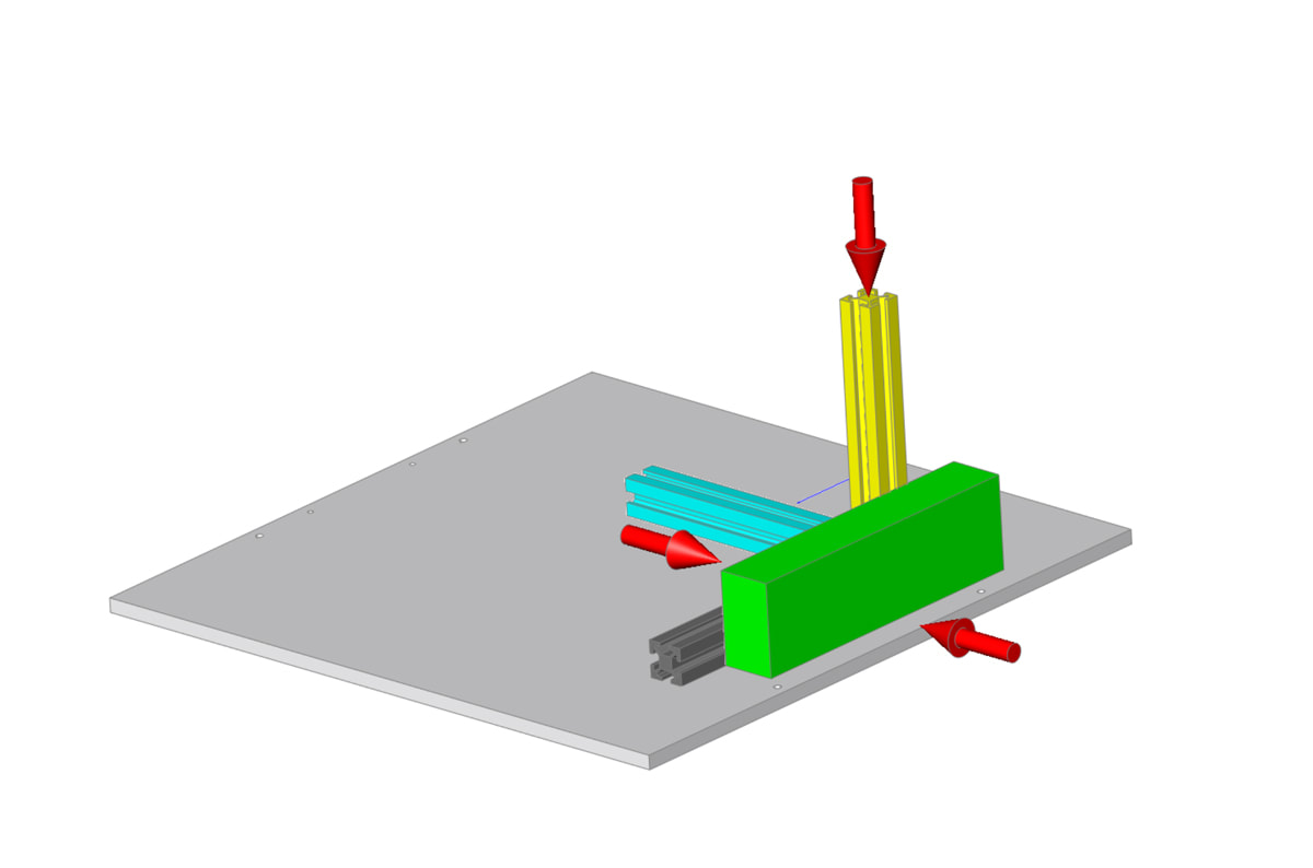
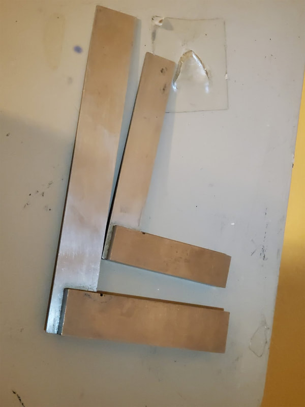
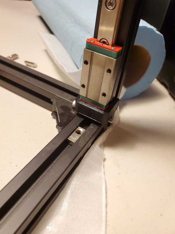
It was simple to fix however, and if I built another one I would probably assemble the cube first taking some care, but not wasting a lot of time (and not doing a final tightening on the screws, but they should be tight). Then I would set the bed plate down on solid surface (if you don't have a wobbly card table, don't worry, a granite surface plate or granite countertop will do in a pinch). Then, for each corner, I would loosen the rails attached to just the one corner (at both ends of the rails if possible), and then, pressing the corner down onto the plate, use the side of something flat (I used a machinist square, but another 2020 extrusion would also work) and just using hand pressure to clamp one rail to the vertical, I would tighten down the one screw. Then repeat for the other extrusion which goes into the vertical extrusion. Reading what I just typed, I realize it sounds like word salad, so here are some pics (the green block is just something perfectly flat like my machinist square or another spare 2020):
It was simple to fix however, and if I built another one I would probably assemble the cube first taking some care, but not wasting a lot of time (and not doing a final tightening on the screws, but they should be tight). Then I would set the bed plate down on solid surface (if you don't have a wobbly card table, don't worry, a granite surface plate or granite countertop will do in a pinch). Then, for each corner, I would loosen the rails attached to just the one corner (at both ends of the rails if possible), and then, pressing the corner down onto the plate, use the side of something flat (I used a machinist square, but another 2020 extrusion would also work) and just using hand pressure to clamp one rail to the vertical, I would tighten down the one screw. Then repeat for the other extrusion which goes into the vertical extrusion. Reading what I just typed, I realize it sounds like word salad, so here are some pics (the green block is just something perfectly flat like my machinist square or another spare 2020):
One thing I made sure to check while going through this process on each corner, was that the edges were flush between the adjacent extrusions after tightening each screw (that is the side where the green block in the above pics was pressing against). If it was not flush, I would loosen the screw and start over. This seems like it would be the simplest method since the rails tend to be more prone to losing a perfectly set position before they are assembled into a cube, and this way only one corner is removed from the cube structure while it is being corrected, and then the next one and so forth. It was important I think to loosen both ends of the extrusions being adjusted though, which gives the maximum amount of freedom to adjust the corner being worked on, and does not introduce a twist on the far end of the rail (this is not possible on the last corner of the top or bottom of course). After doing this on every corner, I found it was just about perfect (to the accuracy of my metric tape measure) when checking for squareness (measuring the diagonals of each side).
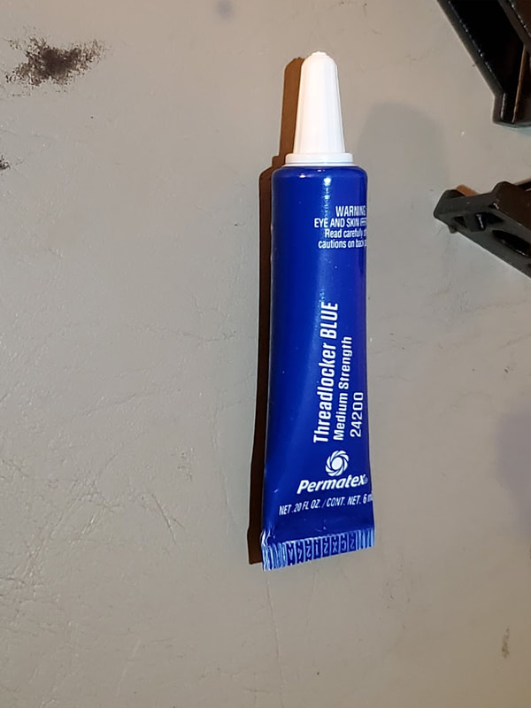
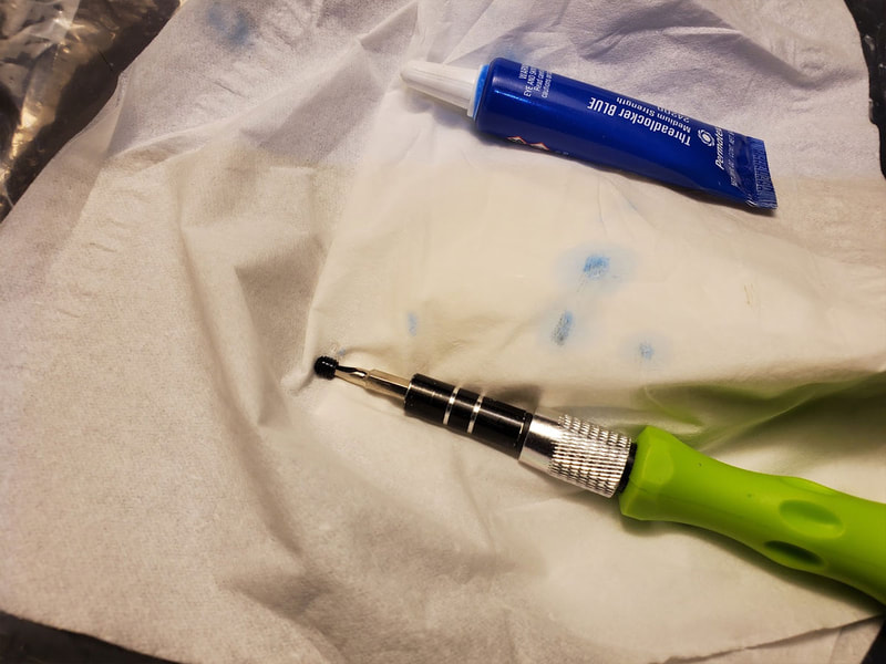
I also used a small dab of blue threadlocker (damn messy stuff) in every hole where a screw would go, then I cleaned up the mess that leaked out of the threads using q-tips and some alcohol. Why somebody has not invented a tube of threadlocker that doesn't leak is beyond me, but they would surely deserve a Nobel Prize or something. Here are a few more random pics from the assembly. You may notice some 2020 corner angles mounted in the pics below. I did use some of those to assist with holding the frame together during the alignment of the corners, but in the end they were removed, since I found them to be not that great anyway (and in the way of some of the components which mount to the frame).
I also used a small dab of blue threadlocker (damn messy stuff) in every hole where a screw would go, then I cleaned up the mess that leaked out of the threads using q-tips and some alcohol. Why somebody has not invented a tube of threadlocker that doesn't leak is beyond me, but they would surely deserve a Nobel Prize or something. Here are a few more random pics from the assembly. You may notice some 2020 corner angles mounted in the pics below. I did use some of those to assist with holding the frame together during the alignment of the corners, but in the end they were removed, since I found them to be not that great anyway (and in the way of some of the components which mount to the frame).
Rails and Z-Axis Stuff
Deciding on a lube for the rails took me some time. I've used linear rails on my first printer (a Kossel), and there I used some SuperLube which worked OK (just gotta be sure to go light on the stuff), but I had read several things about the Voron needing this or that lubrication. The best lubrication for a cheap Chinese MGN9 rail is one of the rabbit holes I hope to never have to fall into again. In the end I decided not to spend $20 bucks on a tube of Mobile EP2 lube, which I will probably never use 90% of, and instead just ordered some superlube - but this time I am gonna try it in the Superlube high viscosity oil version. I know, I know, Superlube has PTFE, which is not recommended by Mitsumi or other purveyors of fine quality linear rails. Buuuuttttt... the rails I have are cheap no-name Chinese clone rails, so I think anything goes, right? Joking aside, and understanding that lubes with additives are "verboten" by the linear rail mafia, I will take the risk in this low load application. The reasons for going with the superlube over grease are firstly, the Superlube should not affect the seals (though I doubt the seals are natural rubber anyway), secondly my experience with Superlube has been good (it is low maintenance and does not dry out), and finally it doesn't have any real smell, and is even safe for use in equipment used to make food (according to the label it says it is "food grade" "NSF (H1) Registered"). The last point is not a big deal though, since I'm not going to use the Voron as an easy bake oven. I would also add a forth, which is that the stuff is cheap and available in a small bottle so I don't have to buy a pound of the stuff to use a few grams. I am also pretty sure I will be able to use it on other things, since it is safe on plastics as well.
I also decided to try some Silicone Nitride ceramic ball bearings in the X and Y axis, which is definitely overkill, but I have always wanted to see if the hype is real. I picked up two (2x) hundred 1/6" (1.588mm) Si3N4 bearings for the two Y MGN9 rails, and two (2x) 40 3/32" (2.38 mm) Si3N4 bearings for the MGN12H which is on the X axis (note that is two packs of each for a total of 200 1.588mm bearings and 80 2.38mm bearings). I am not changing the balls in the Z axis rails, which will use the steel balls they shipped with.
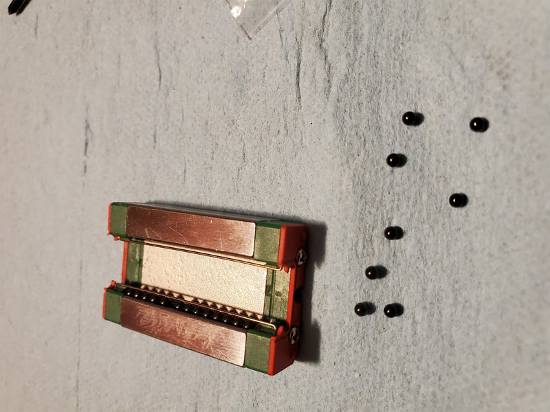
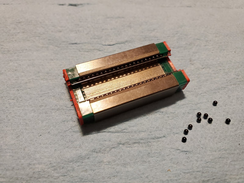
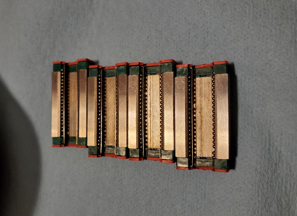
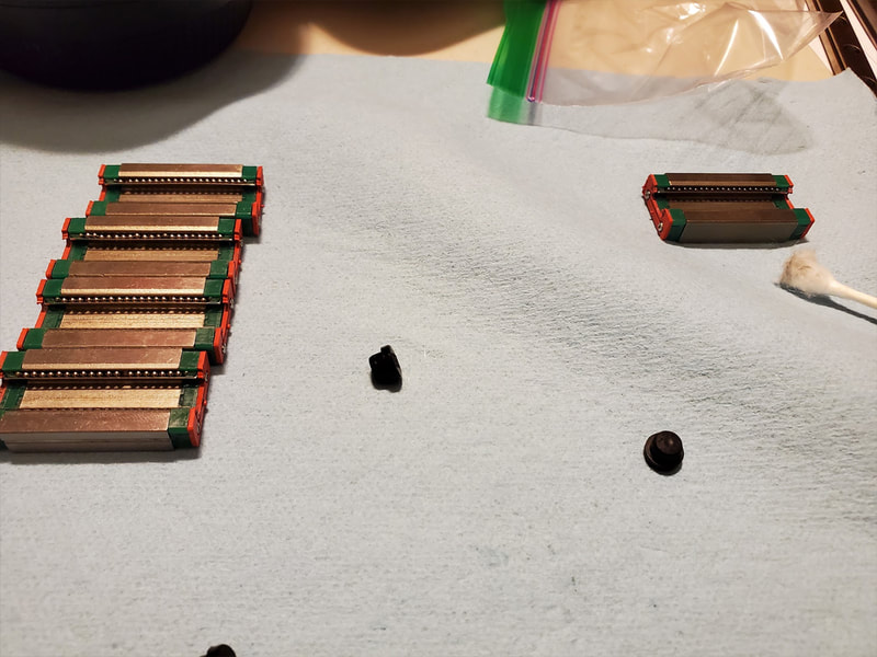
Because I had previously lubed the bearings with grease, in my haste to get something done (before I decided to use the superlube oil), I had to re-clean the bearings and used some paint thinner (mineral spirits) to do that. I went ahead and removed and cleaned the balls as well since I was changing to a synthetic oil. Re-balling the blocks is a pain, but it is probably the only way to make sure all the grease was removed from the channels. I first loaded up the balls in the blocks (dry without oil) and then when they were all set up, I added a small amount of the Superlube oil to lubricate the ball bearings, and added a couple drops to the rails as well (and then wiped everything down after it was circulated around). To help get the blocks loaded on the rails, I used my finger to press the bars apart as I slid the rail on. That seemed to help to keep the balls from popping out while the rail is installed, but it can also be done with care and going slow. The rails are now really smooth, and I can see the balls moving correctly in the tracks.
Step 1 (B) - Inserts
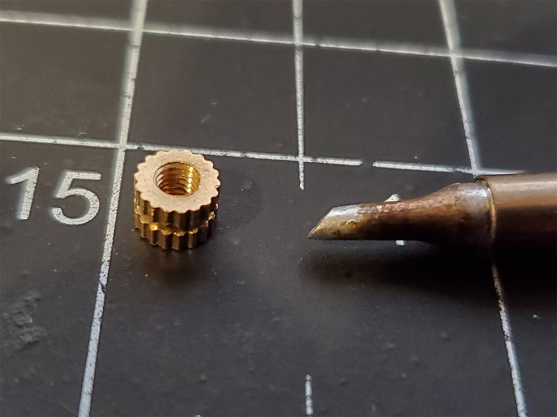
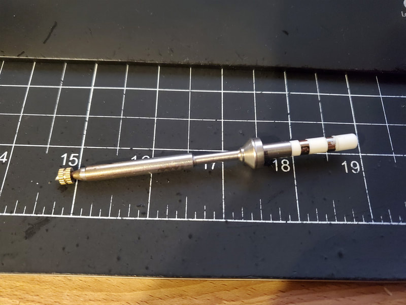
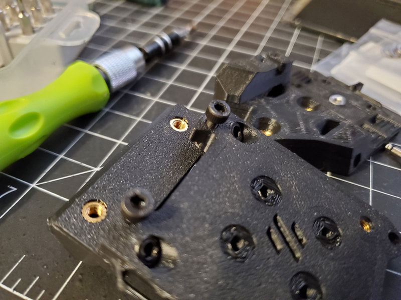
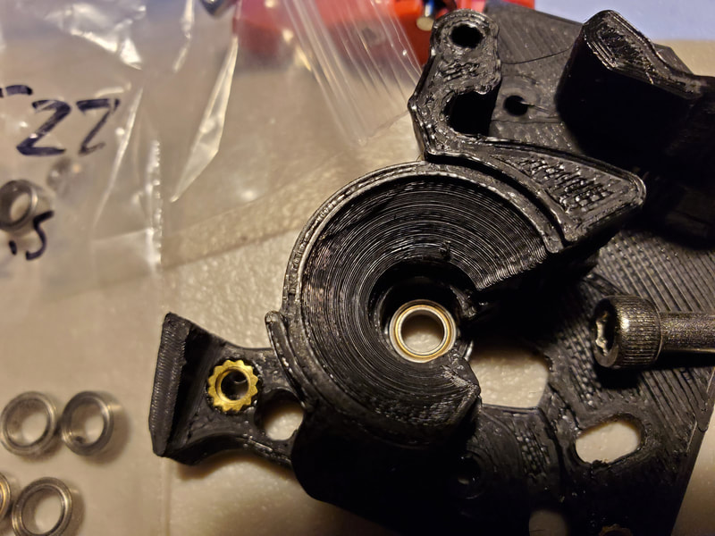
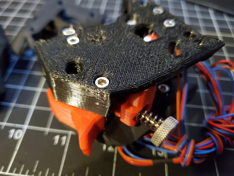
I didn't plan to mention this since it is just part of the process, but I thought I'd drop a note on how I install the brass M3 inserts in the parts. I used two methods depending on the type of hole the insert would go into. If the hole is a through hole, I used my Pinecil soldering iron with a BC2 tip, heated to 330°C (note that the Pinecil uses the same tips as the TS100). The soldering iron method is quick and really consistent, however sometimes the inserts will stick to the tip of the iron, so having a tweezers handy to help remove the iron (but not the insert) can help. This tip is too long to use with a hole that does not go through however, so when there is an insert which goes into a shallow pocket without a through hole, I use another technique.
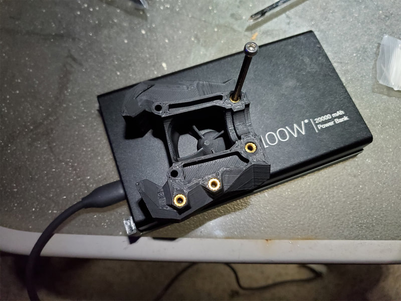
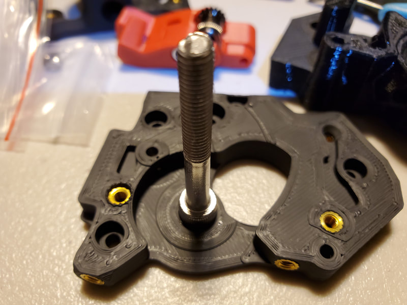
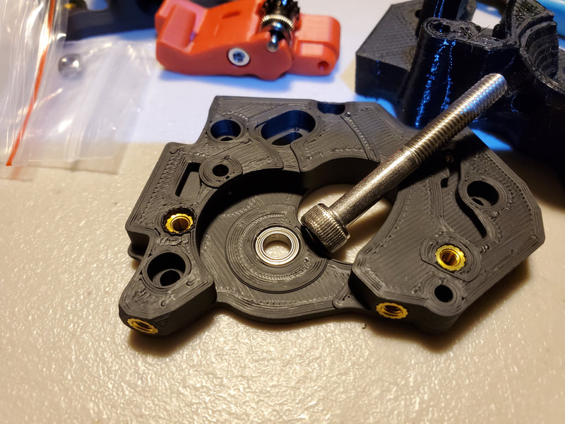
To install the inserts where I cannot use the iron, I use a long (at least 30mm) M3 screw, held by a pliers, and simply thread the insert a few turns onto the end of the screw. Then I use a jet lighter to heat the insert for about 3 seconds and then simply press it in place. I candle also works, if there is no jet lighter handy, but will take a couple more seconds to heat. This method seems more accurate since the screw helps as a guide to make sure the insert goes in straight and can be tweaked a bit for a couple seconds after installing the insert. The temperature however is not as consistent as the soldering iron method, so it can take some trial and error to get it right. It is also however very simple and cheap.
Before embarking on the mini-project of installing the inserts for the kit, I went over the manual for the Voron 2.4R2 and the Stealth Burner and looked for any instance of "insert" being mentioned, and also looked closely at the pics as well (looking for where the inserts would be placed). It is easy to find some of the insert locations, but some are not as obvious when looking at the parts, so going over the docs and then using them to install the inserts was the only way to go - and I'm sure I still missed one or two along the way. Also as a side note, the M3 inserts included with my kit, were the correct type, and there were plenty of them. There are a few types of M3 inserts, and these are the type which have a step which makes them easier to start.
Here are some pics I took while installing the inserts, pardon the mess, I moved everything outside due to the stink from the melting ABS, which is definitely something to avoid. I also had a fan blowing across the work area to move the fumes away, and that helped quite a bit with the smell. Something that may be interesting is that the battery bank in the pics is a 100W PD bank, which I am testing for use with the Pinecil (so far it has been working great). I'd not recommend using a battery bank as a work surface though. This one is aluminum, but still, it was not my best idea.
The next step is to install the rails on the frame.
Step 1 - Install the Z-rails on the frame
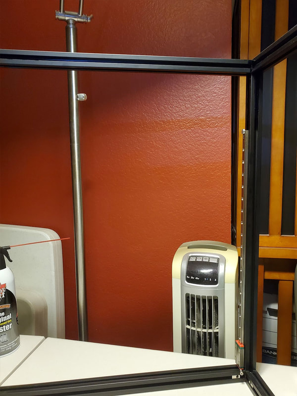
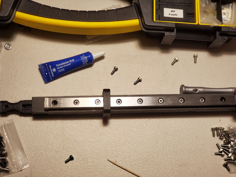
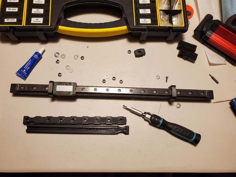
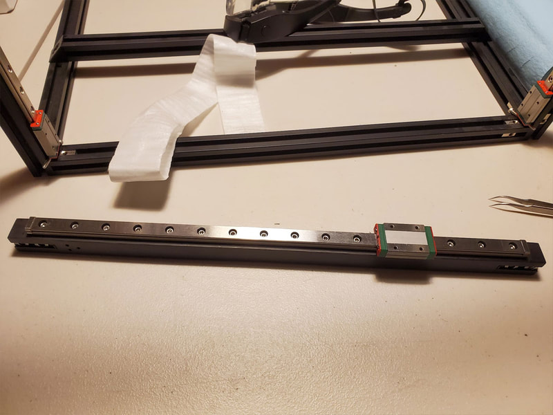
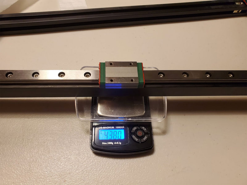
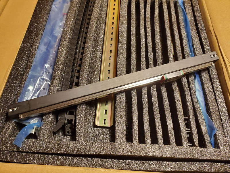
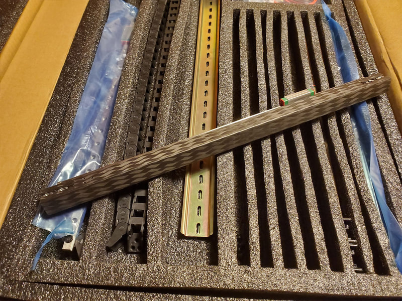
This was actually simpler than I expected, though tedious. The Voron design and instructions are really optimized and easy to follow so far. This is really just installing a bunch of roll-in 2020 M3 nuts and installing the rails using the MGN9 rail centering jig. The base of the rail is supposed to be 3mm from the bottom of the printer, so I used a long M3 screw as a gauge to set that offset.
Step 1 - Z Steppers and Feet
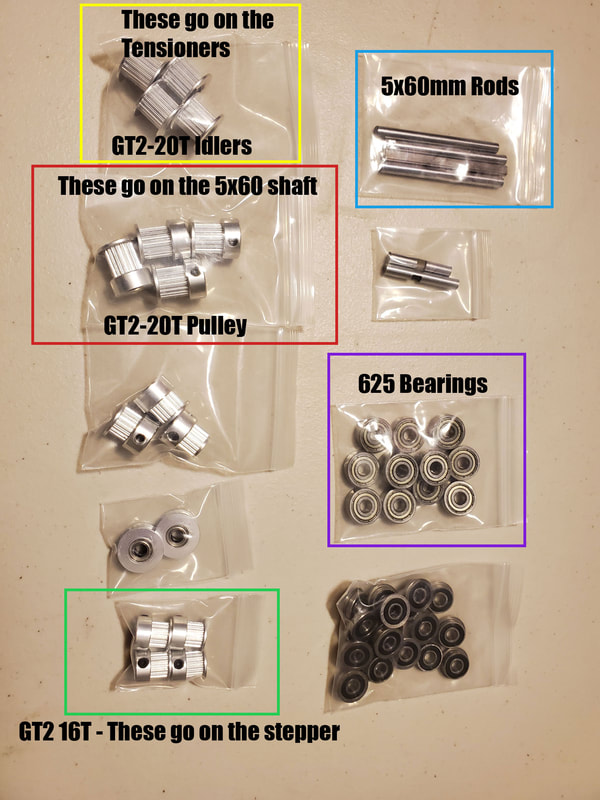
I'm not showing the install of the acrylic floor pan and the DIN rails, since they are pretty simple (but they go in before installing the Z steppers and feet). The Z-Steppers have some M3 brass inserts which need to installed prior (see above on how I did that using a Pinecil soldering iron). The Z-drive uses four GT20T 9mm wide pulleys, and the larger GT80 tooth pulley, which go on a 5x60mm shaft (hopefully with a D profile), with three 625 bearings and four M5 shims. Note that the GT20T 9mm pully is the larger one and goes on the 5x60mm shaft, the smaller GT16 pulley goes on the stepper (the smaller ones are unique since they are the smallest pulleys in kit). I used some Permatex blue threadlocker on all the grub screws, and it is important that one of the grub screws sits on the flat of the 5x60mm rod, which helps to keep the pulley locked in place. Just a small dab of the threadlocker is all that's needed, the stuff is very messy as well so it helps to have some tissues or paper towels to keep it under control.
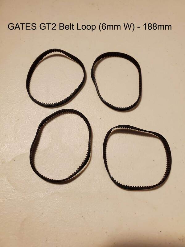
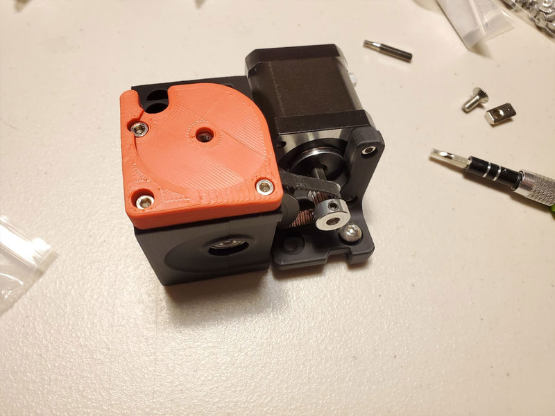
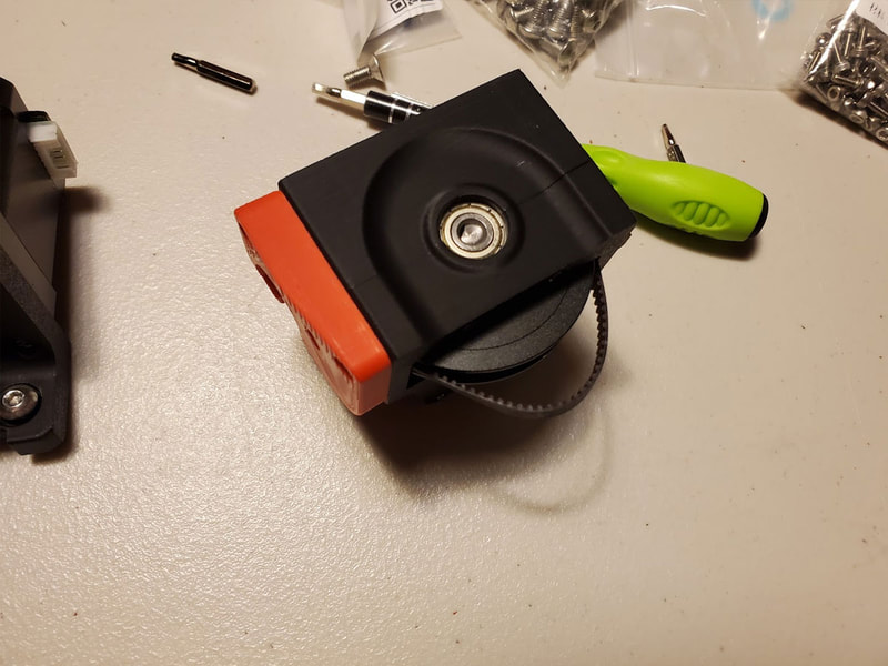
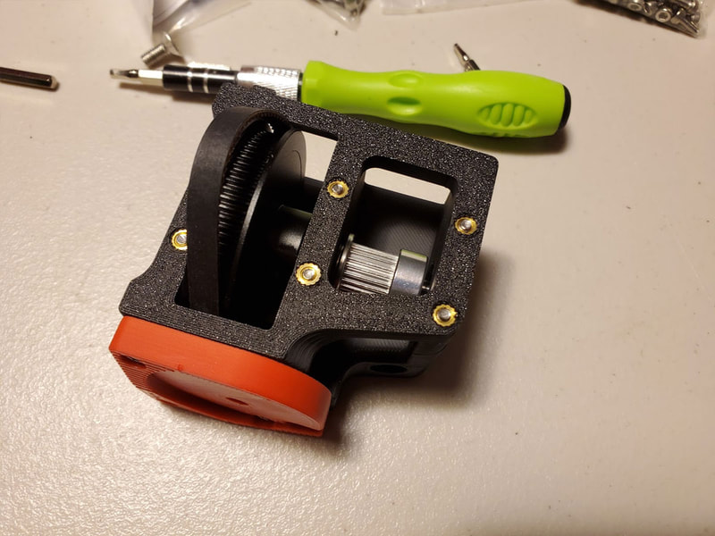
I missed getting pics of the assembly of the assembly of the Z axis gear train, but below are pics showing it assembled. The only things to note are to be sure that the belt does not get pinched while putting the halves together (and that the belt is installed before closing the halves). I tightened the M3x40mm screws down by moving in a zig zag fashion (diagonally), and moving through them in two passes, the first being snug and the second pass being the final tightening. The ends of the M3x40mm screws were just about flush with the ends of the brass inserts when it was fully tightened down.
There is an M5 nut (which holds the rubber feet), which needs to be installed in the red colored cap, this was pretty loose in my parts, but it did not cause a problem (just be carful when installing the red cap to be sure the nut does not fall out). Once the red cover is in place the nut will be held in place enough by the 80T pulley that it should be OK until the feet are installed. It could be glued in if the looseness is a bother though.
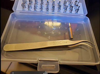
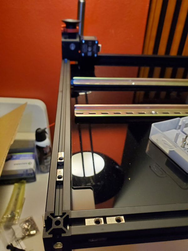
Installing the Z-steppers was pretty simple, however there is one primary consideration, that is to make sure they are installed in the right place. It sounds easy but at this point the frame is still pretty bare and it can be hard to see which is front and back versus the sides. Refer to the manual as always, but just keep in mind that the orientation is easy to miss here. Four M5 roll in 2020 nuts are installed on each corner (two on one rail and two on the other). A pair of long hooked nose tweezers is really handy to align the roll in nuts. The tweezers helped to roughly position the nuts, and then fine tune the position with the parts in place, using the tweezer to hook the roll in nut and push or pull it into position.
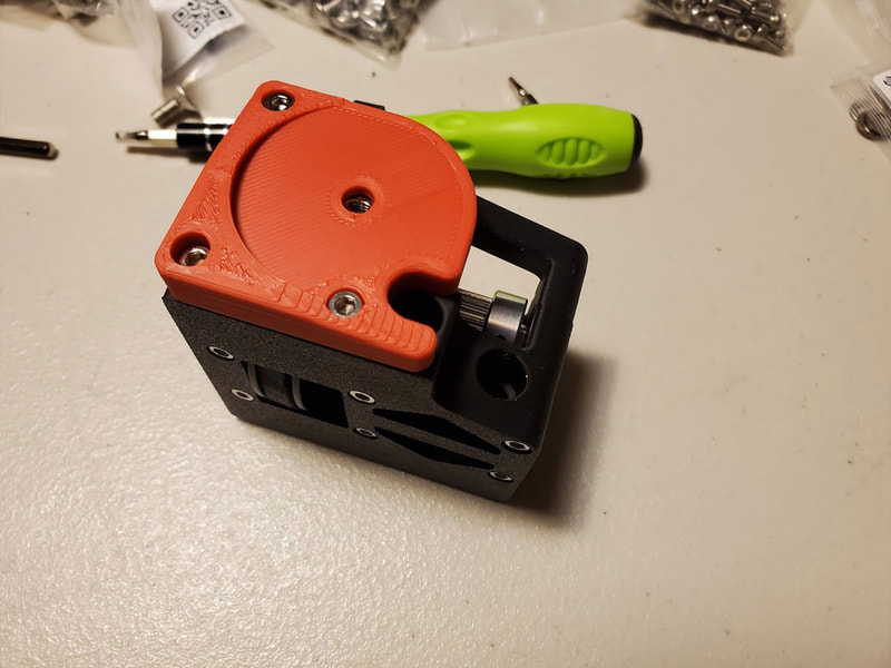
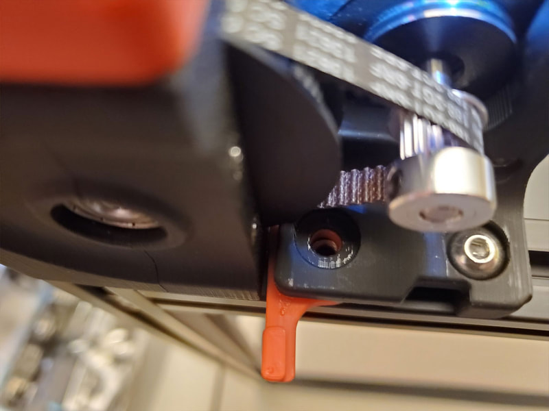
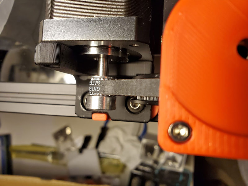
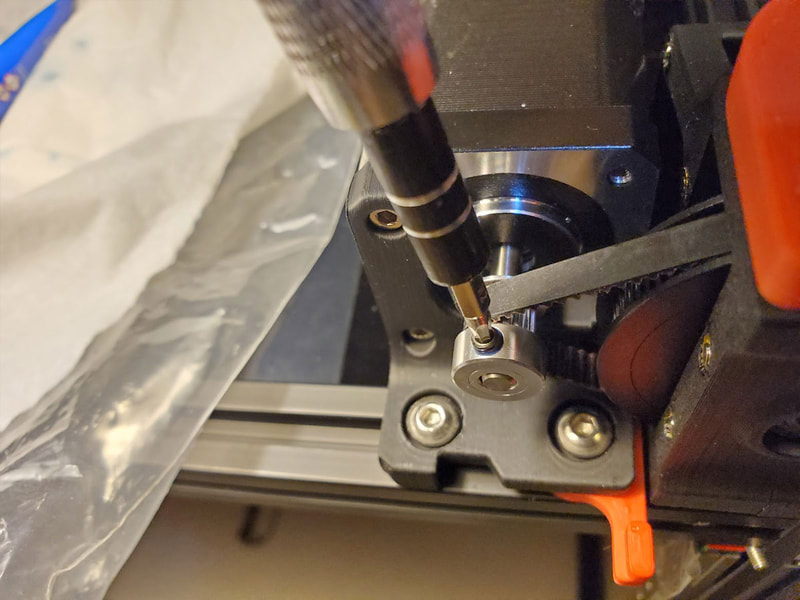
The gear train installs first using M5x40 screws, and is actually very easy to get aligned, just take care not to pinch the belt as I did on one of them. Next, the Z stepper with the GT16 pulley goes in. I did not tighten down the pulley yet, even though the manual recommends doing that in an earlier step. I decided to get the Z stepper in place first, and then I aligned the GT16 pulley with the old eyeball v1.0, and when it looked good, I tightened the grub screws down (using threadlocker and making sure one grubscrew is on the flat of the stepper shaft). Once I was happy with the alignment and had flipped the red locking tab to tension the belt, I tightened down both screws holding the Z stepper (though I think the manual suggests leaving these slightly loose for adjustment, so that was just my preference).
The manual recommends installing the Z steppers in alternating corners first, which should help to keep the frame square.
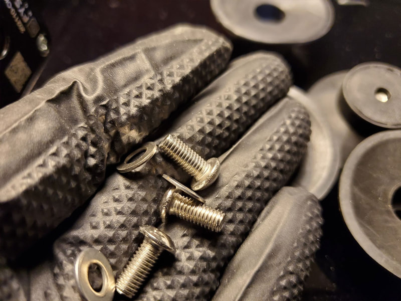
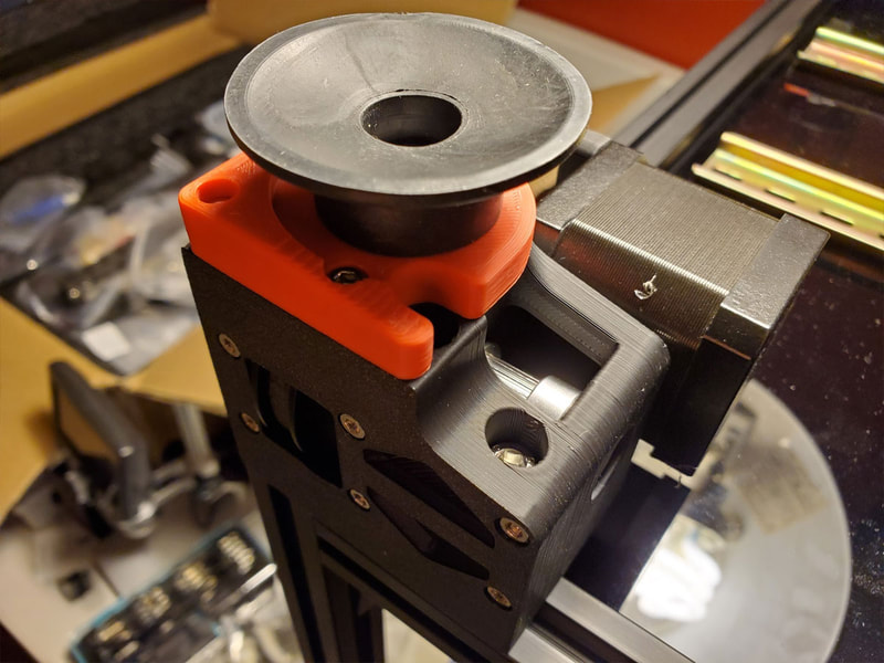
Next is to install the feet. The manual recommends using M5x16 screws for this, however the feet which shipped with the FYSETC kit do not have washers integrated, and are a bit thinner I think, so I added an M5 washer and used some M5x12 screws which seemed to work fine (I did not want a longer screw to possible stick out and rub against the belt or GT80 pulley).
Next is to install the feet. The manual recommends using M5x16 screws for this, however the feet which shipped with the FYSETC kit do not have washers integrated, and are a bit thinner I think, so I added an M5 washer and used some M5x12 screws which seemed to work fine (I did not want a longer screw to possible stick out and rub against the belt or GT80 pulley).
The last part for this step is to install the Z-Axis belt tensioners. I've ordered some aluminum tensioners because I can't resist a deal, and they were on sale, but it's very likely not much of an improvement in terms of how well they tension the belts, but I think since they have a knob, they will be easier to adjust. However I could have just printed some similar tensioners with a knob to adjust the tension though. But since I don't have the upgraded (I hope) parts yet, here are some pics of the stock idlers being installed.
Not much to go wrong with these, but it does help to verify they are in the right spots before installing em. I also set each one to 10 turns of tension, so they would be pretty closely matched when it comes time to actually tightening the belts. I am happy I upgraded these those, since I feel they will be a bit of a pain to adjust with the belt in place.
Not much to go wrong with these, but it does help to verify they are in the right spots before installing em. I also set each one to 10 turns of tension, so they would be pretty closely matched when it comes time to actually tightening the belts. I am happy I upgraded these those, since I feel they will be a bit of a pain to adjust with the belt in place.
Step 2 - The Bed
I had considered using a kinematic bed, however it's not a drop in thing for the FYSETC kit, since the bed is not drilled to the Voron 2.4 spec (though it is still perfectly fine). I've also read that the kinematic bed may not be needed in most cases, so I'm gonna just install the FYSETC bed with the stock mountings, and see how it goes. I may add some silicone standoffs instead of the stock steel standoffs (with the hope that they may insulate the frame somewhat from the bed), but that's just a possibility right now.
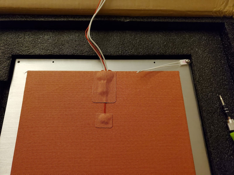
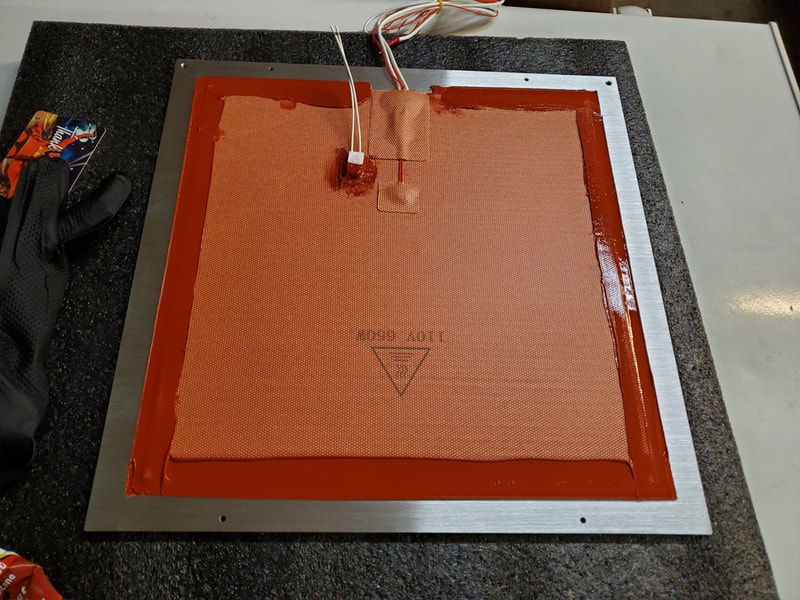
If you are gonna build any Voron or RatRig or similar printer, I highly recommend checking out Nero3D on YouTube. I found his video on installing the bed heater and took his tips to heart when I set up my bed. Specifically I really liked his thoughts on applying the thermal fuse to the silicone heater versus the aluminum bed. It makes sense that if the fuse is needed, it should be attached to the bed, and since the high temperature silicone should give out at a much higher temp than the fuse it should stay firmly attached to the heater. I also ran some high temp silicone around the perimeter of the heater to give some extra protection (this is just a backup to the 3M adhesive on the heater itself).
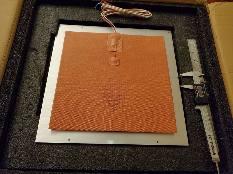
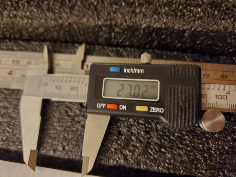
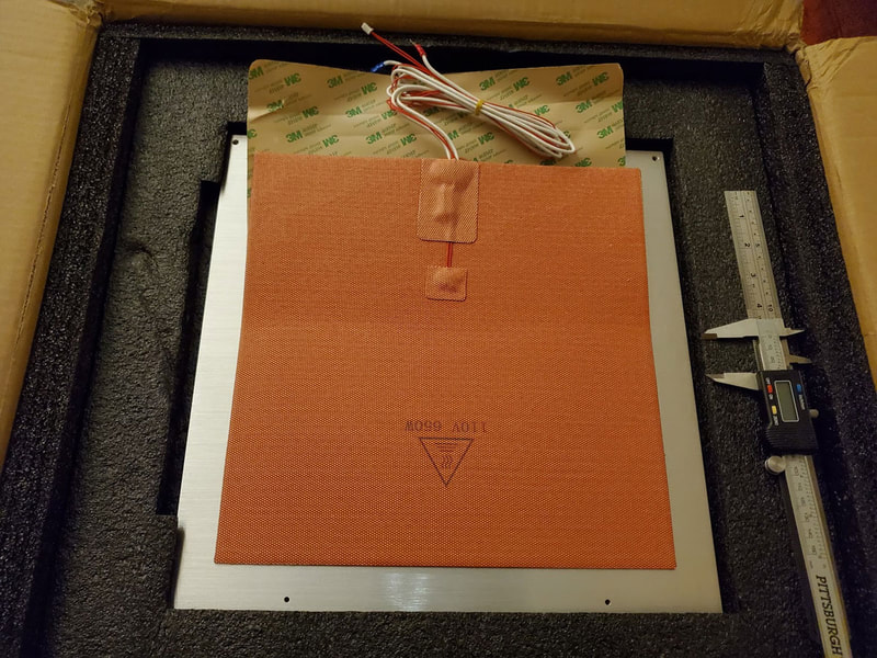
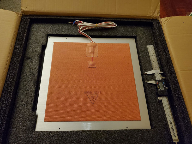
To set up the bed, I first cleaned it with alcohol and let it dry. Then I roughly set the heater in the center and measured the uncovered space around the edges. I found that it was about 54mm give or take a couple mm, so I set my calipers to 27mm and used it as an aid. Next, I peeled back just an inch of the backing from the heater and tried to center the heater as close to center as possible (not going for perfection just good enough here). Then I started to stick down one corner and realized it was backwards (doh!), but fortunately it was easy at this point to lift it and rotate it 180°. Once I had it in the right orientation (the two holes need to be towards the rear of the printer, where the wires will route from the heater), I pressed down the inch or so of exposed adhesive. Then I re-checked and pulled back another few inches and pressed that down, working from the center out to remove any air bubbles. That was done several times until it was stuck down, and then I went over it again and pressed it down. Finally I used some cardboard scraps to create a sort of pad to keep weigh off the wires of the heater (as you can see in the above linked Nero3D video), and weighted the heater down with three spools overnight.
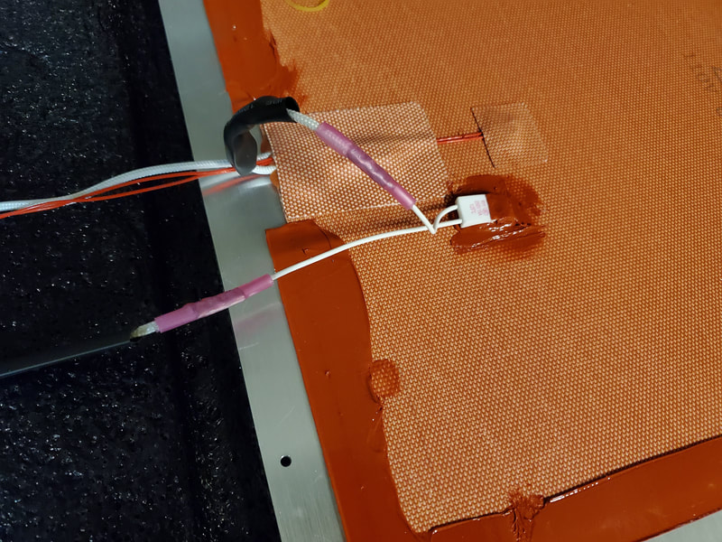
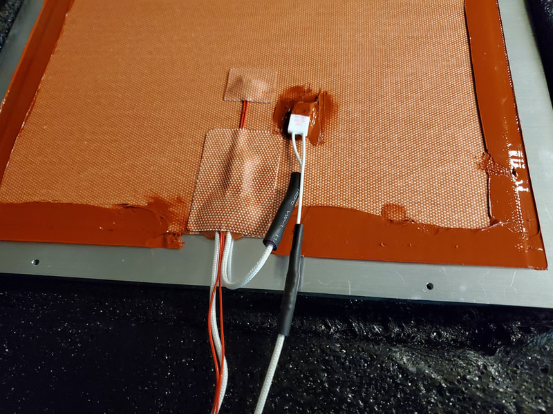
You may have noticed that I also mounted the thermal fuse to the aluminum bed in the pics above. I did, but later decided to mount it on the bed heater as discussed previously. The fuse mounting point on the FYSETC bed is non-standard, being all the way at the edge and using an M5 screw. Nothing really wrong with this, but it will make for a more convoluted wire routing of the bed heater wire, which would need to snake between the bed and 2020 rail in that position. I'm not really a fan of that design choice, but mounting the fuse to the heater itself lets me position it just about anywhere.
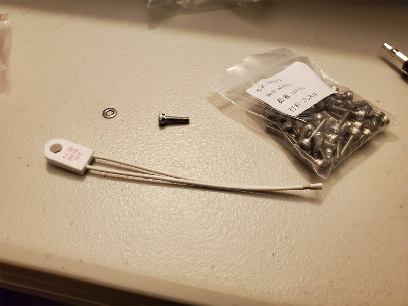
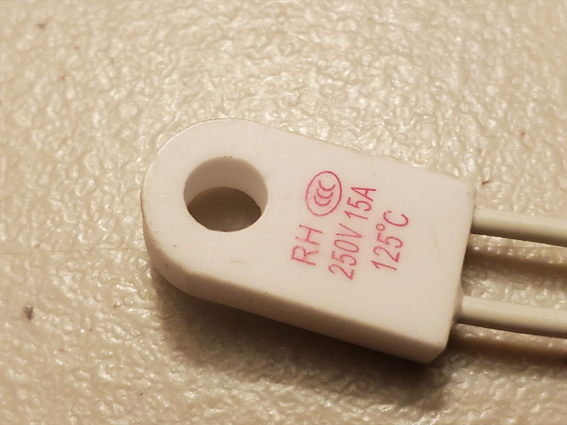
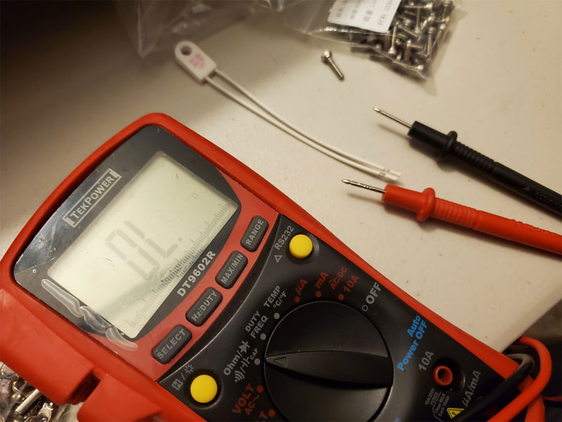
Before mounting the fuse, I tested it to make sure it was good. To do this I used my multimeter, set to the continuity setting (which on my meter requires turning the dial to the right position and hitting "select" twice. I didn't get a good pic of this test, but all that needs to be done is to connect the probes to each end of the fuse wires and it will beep if it is good (if there is continuity, meaning the fuse is not blown). This is of course done before the fuse is connected up.
Before mounting the fuse, I tested it to make sure it was good. To do this I used my multimeter, set to the continuity setting (which on my meter requires turning the dial to the right position and hitting "select" twice. I didn't get a good pic of this test, but all that needs to be done is to connect the probes to each end of the fuse wires and it will beep if it is good (if there is continuity, meaning the fuse is not blown). This is of course done before the fuse is connected up.
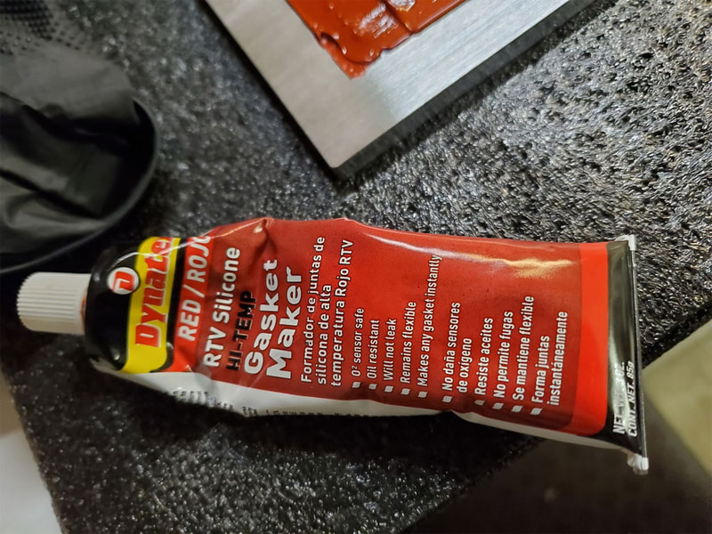
Now that the fuse is tested (and the day after mounting the heater), I went ahead and used some High Temperature Silicone Red RTV to adhere the thermal fuse to the heater, and also sealed around the edges of the heater, which gives some extra protection, if the 3M adhesive should someday fail. I used some painters tape and an old gift card from a theater which went out of business during the pandemic to help with applying the silicone evenly. I first ran a bead all the way around (except the area around the wires which I did not apply silicone to). Then I squeegeed the silicone with the gift card, and when it looked OK, carefully removed the tape. The only tips here are not to play around with it too much, and just try and get it done in one pass, and remove the tape while it is wet. Silicone RTV has a vinegar smell, so I did this in the garage, but it's not really that bad if it had to be done inside, though I guess it could be annoying. This will need to set up overnight before I can mount the bed and crimp the fuse inline with the heater wire.
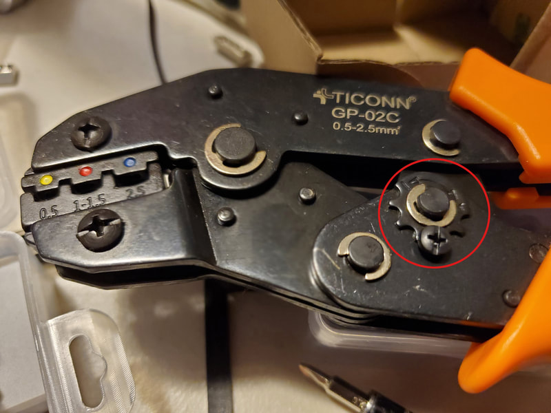
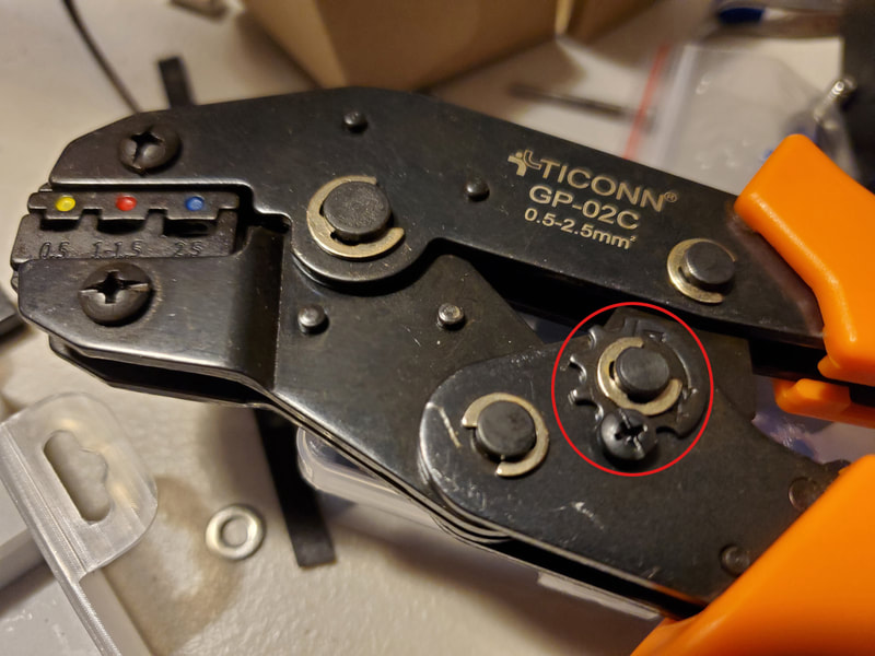
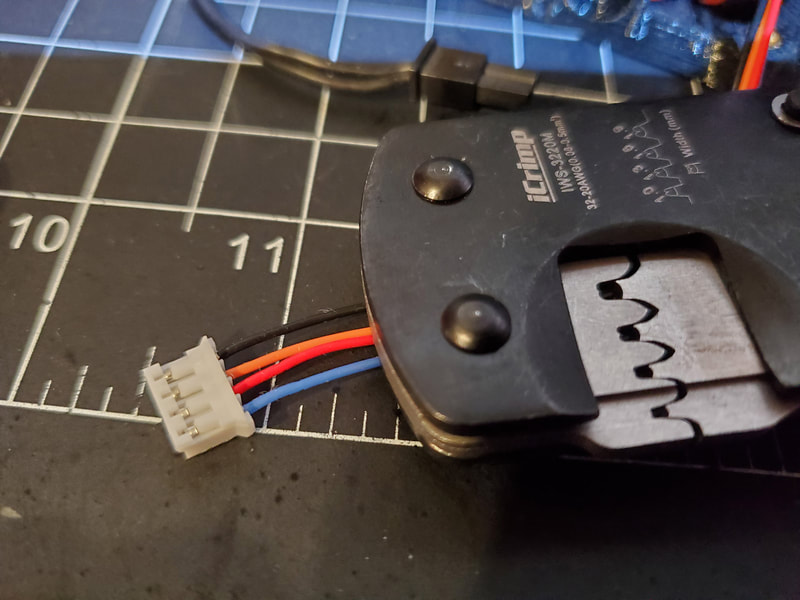
I used some crimp connectors to install the fuse, finding a tool that would not tear the crimp connectors up took a few tries, but I found this tool (by the same company that sells the connectors), and it worked reasonably well. I adjusted the tension wheel one notch wider (circled in the pics below) when I crimped the thicker bed power cables to the connector. I used the second notch (which is how it shipped), to crimp the thinner thermal fuse wire. I think getting a crimper which has a tension adjustment is a requirement for these, since it's very easy to over or under crimp. The crimps should withstand tugging on the connector and wire, but should not be so aggressive that it cuts through the insulation. I made the tension adjustment with the crimpers in the closed position as shown in the pic. I added some hear shrink over the connectors as a bit of extra protection.
I'm setting the bed aside at this point and will mount it after the electronics are installed (since it adds quite a bit of weight to the printer while it's being assembled).
Step 3 - XY gantry
I built the XY gantry with non-stock parts including the following:
Chaoticlab XY Tensioners (currently out of stock but available on amazon - but $20 bucks more)
Funssor Aluminum AB drive Units
FYSETC Carbon Fiber X-Axis Tube (with my printed end inserts)
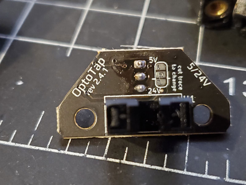
Voron Tap kit (with a version 2.4.1 board which supports 5v or 24v)
Unfortunately I didn't get pics of the assembly for the XY joints. The only thing which I did differently from the manual, was to use some cut down partly threaded M5x45mm bolts (cut down to 40mm) in place of the M5x40mm screws for the GT2 20 tooth idlers, and the F695 bearings. This should be similar to the Pins Mod but without having to print new parts. I used normal M5x40mm screws for all the other bolts on the XY joints.
The Funssor AB drive units were very easy to install and set up. Since the plates have the same (5mm) thickness as the printed parts, the same size screws can be used as with the stock drive units (to mount them to the aluminum extrusions). The plates are also designed with indexing tabs milled into them, which help with alignment of the extrusions. They shipped with aluminum belt clips, which were a nice addition.
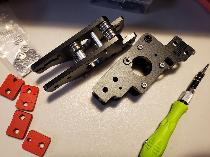
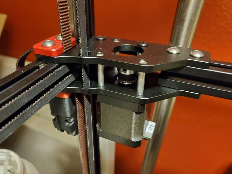
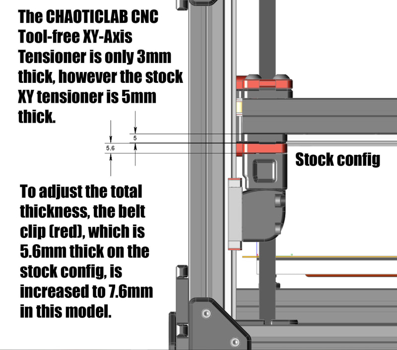
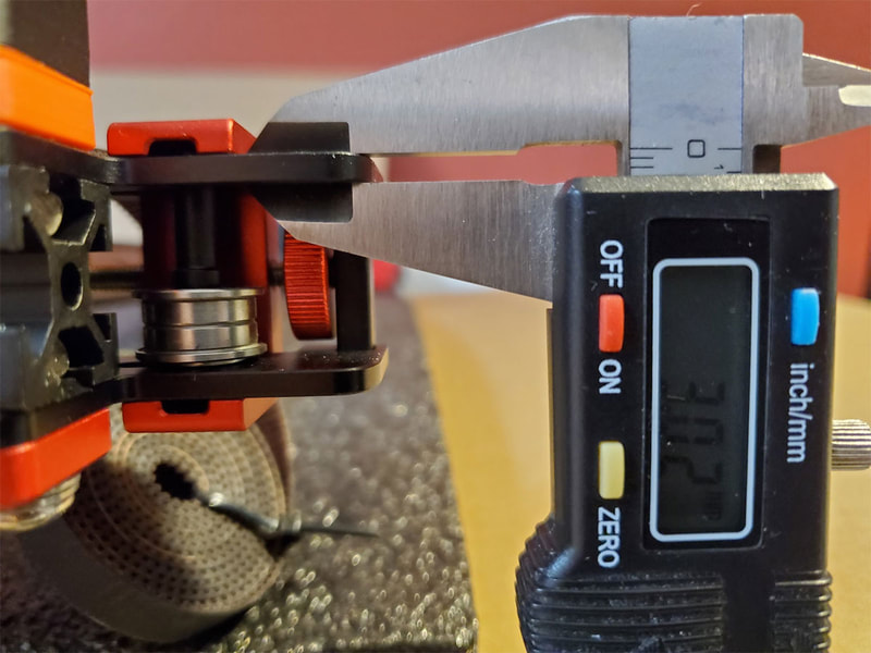
The Chaoticlabs XY tensioners are also well made, however installation had one issue which required a printed part to fix. They are made with aluminum plate which is only 3mm thick, which means the stock M5x16mm screws will not work to hold the belt clips on (they are 2mm too long). I could have just stacked 2 washers, which is what I initially did for the top clips. However the bigger problem with the thinner (3mm vs 5mm) plates is that also means the stack of parts (lower belt clip, z-joint and bearing block) which mount the XY tensioners to the z-linear rails, is 2mm shorter than the stock design. This situation would result in the rear z-joint and bearing block stack ending up 2mm higher than the front. The fix I came up with was to simply increase the thickness of the upper and lower belt clips for the front XY tensioners, to bring the parts back into the stock alignment.
I later decided to remix Hartk1213's Voron2.4_GE5C Z Joint, which I am on the fence with. My remix can be found on Printables, though it is not fully tested at this time. I'm posting it here in the build log, because it's what I have installed, though I am not yet sure if it offers an improvement over stock, or not. Note that some of the pics below show steel GE5C bearings, however, due to quite a bit of slop in those bearings, I switched to IGUS GE5C bearings, which have zero noticeable play. I'm using M5x8x6mm aluminum spacers, and a couple washers which can be seen in the third pic below (though I plan to replace them with M5x8x8mm spacers so I can remove the washers):
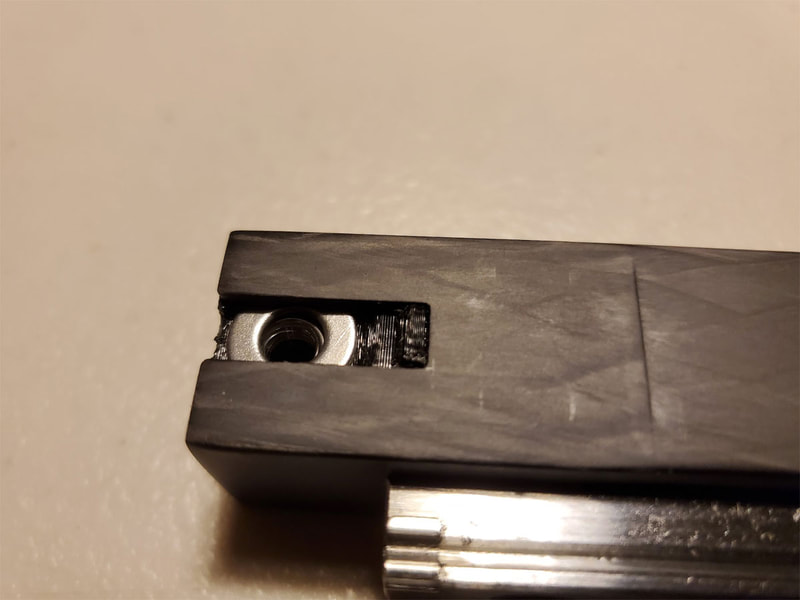
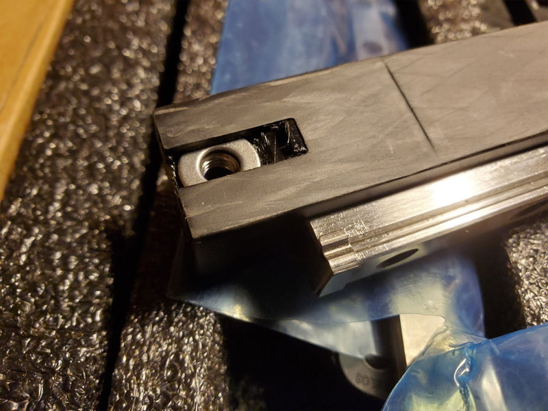
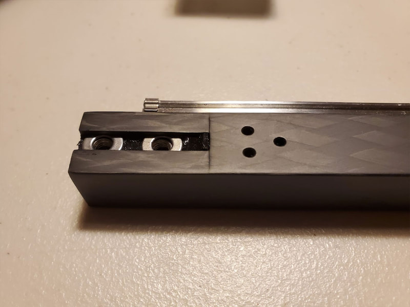
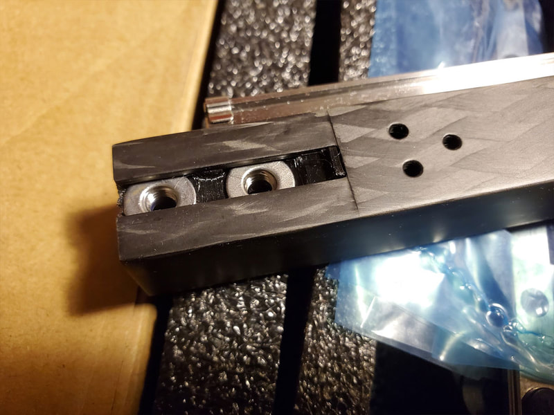
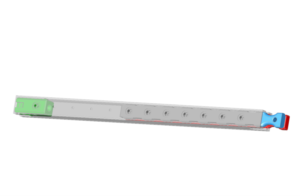
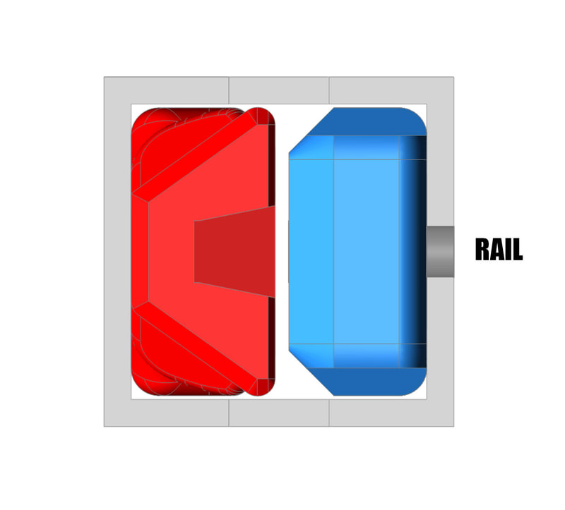
Finally, the FYSETC Carbon Fiber X-Axis Tube (with my printed end inserts) went together pretty easily and looks great. I wrote a post about it here, which I'll just summarize. The FYSETC CF X-axis tube has pre-drilled holes to mount the steel linear rail, however they are not accessible with a wrench, so I first had to design a tool to assist in installing lock nuts inside the tube. The second problem with the CF rail, is that there is no way to hold the nuts that would slot into the rail ends (which hold it to the XY joints). To address that issue, I designed some end plugs which each hold three M5 nuts and washers, which are slid into the ends of the rails and hold the nuts in pockets so they can be tightened. Both the tool and the end plugs are posted on Printables here. After installing the rail, I'm happy with the way it went together and I hope it will work without the deflection issues that I've heard CF rails can suffer from, but time will tell. The FYSETC tube does seem to be a pretty sturdy CF design though, with walls that appear thicker than some which I looked at (in pictures).
Tappety Tap Tap
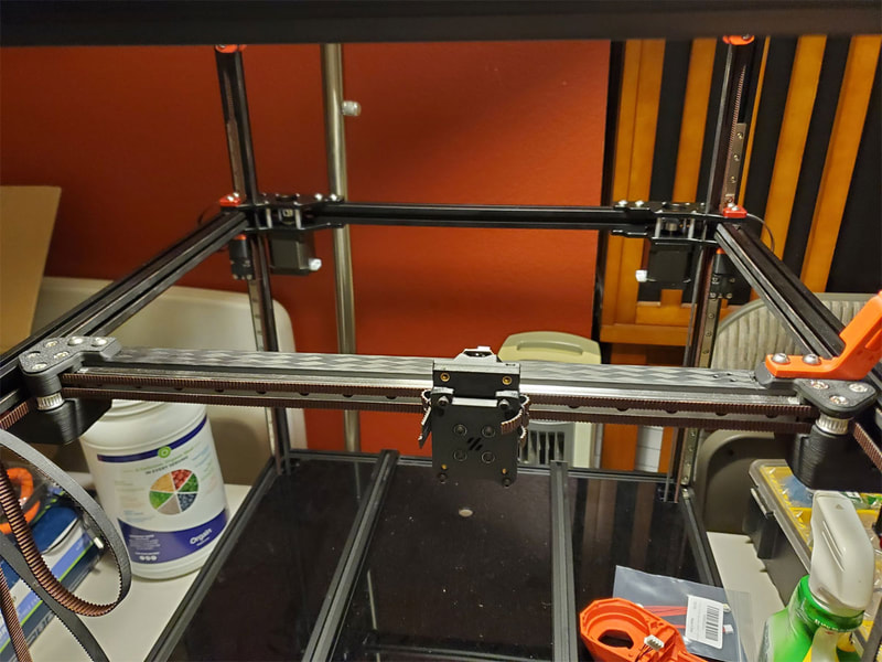
The last part of the XY gantry setup was the installation of the belts and installing a Voron Tap kit. The kit I bought included the printed parts and went together pretty easily. The Voron Tap is a zero offset probe which adds some weight, but gains the benefits of a zero offset optical z-probe (which seems worthwhile). Other options are a clicky probe which can dock and is only used when the printer is probing, as well as other mounts for BL-touch or the stock inductive probe. For now, I think the Tap is the best option, at least until somebody comes up with a loadcell tap probe for the voron (which would have all the benefits and none of the weight penalty).
The Voron Tap is really well documented, so I will not go into the assembly much, but will share some pics I took during the build, and note things I did differently. There is also a great video here, from Nero3D, which explains the setup process.
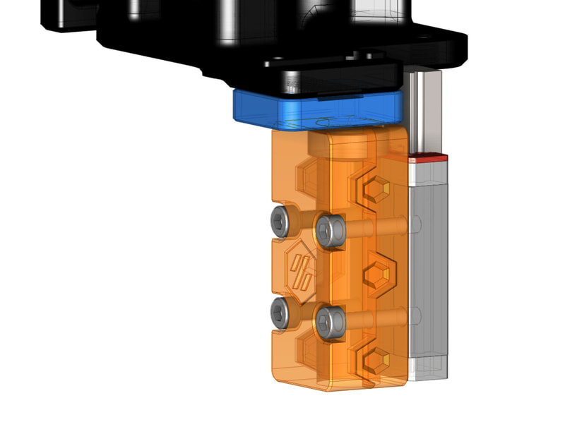
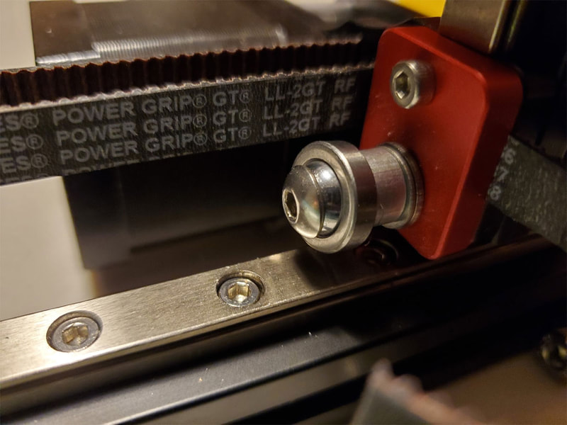
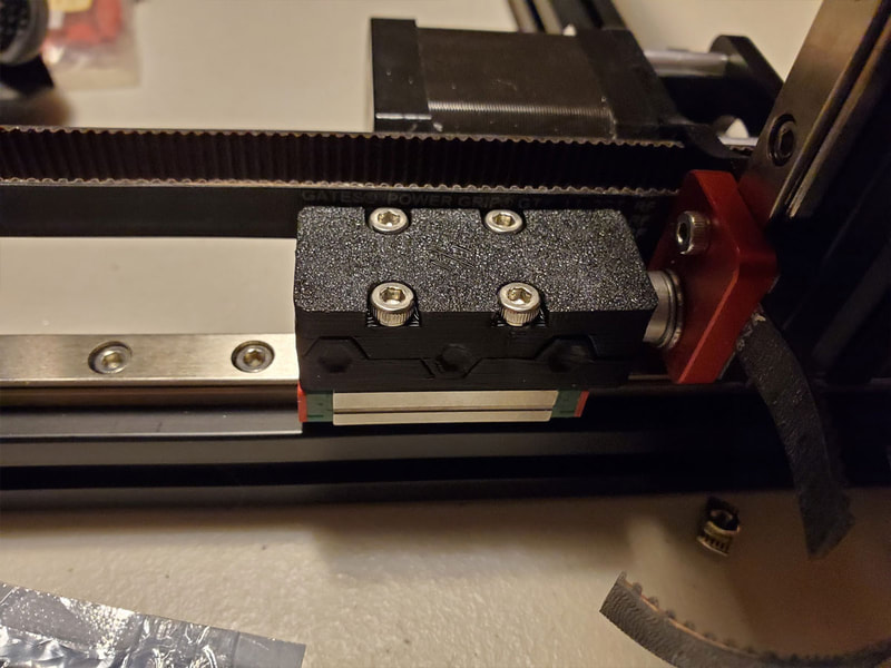
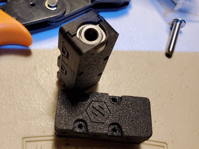
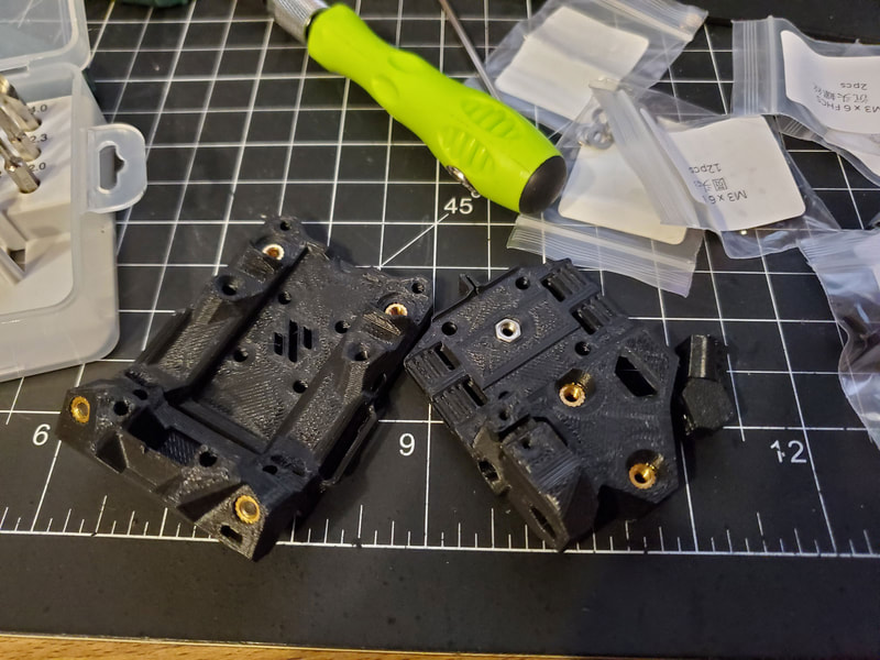
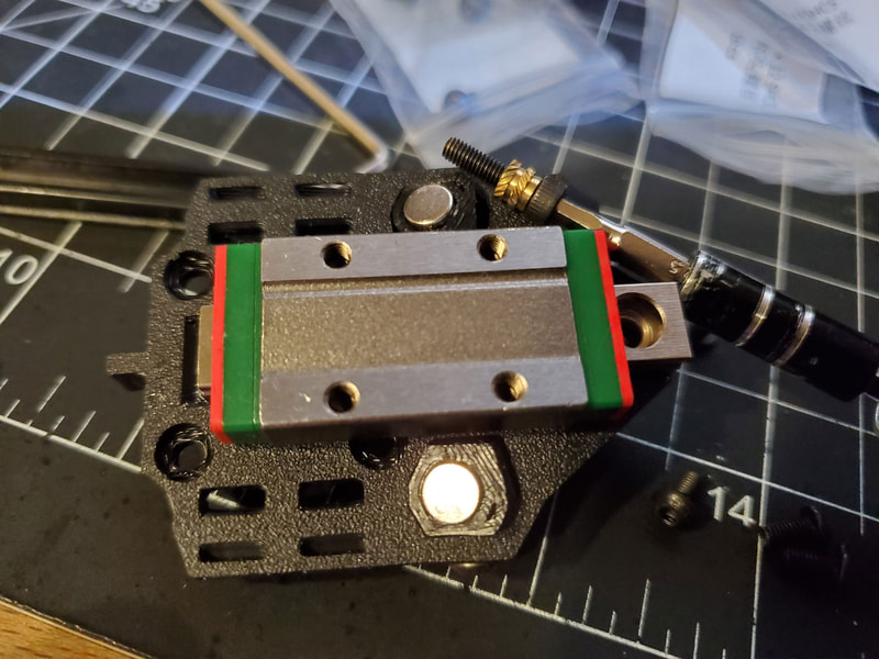
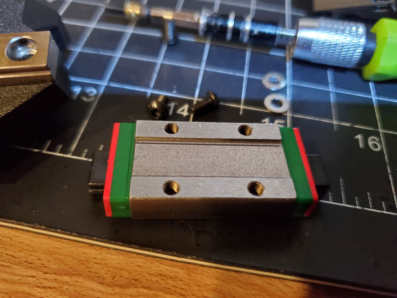
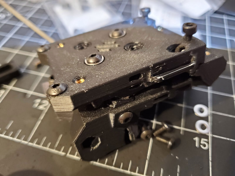
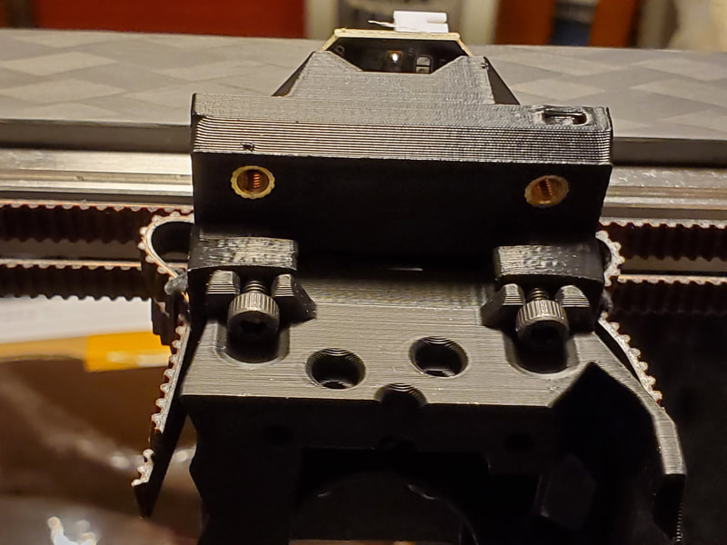
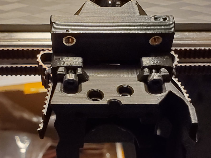
One issue I had was that the magnets did not fully seat in the odd shaped parts that hold them, however that did not seem to be a problem in the end. I didn't degrease the linear rail, but I did add some Superlube oil to it. I also found that the bolts which catch the hot end assembly of the Stealthburner, needed to be set a bit further out than the manual suggested. I just test mounted the hot end assembly and adjusted the screws. The last minor problem I ran into was that the plastic dummy rail provided in my kit was too tall to use in the manner the manual suggested, that is to install the bearing block from the top. Instead I removed the bottom screw in the rail (the one with the brass insert as a standoff), and installed the block by aligning the plastic dummy rail from the bottom and sliding the block off the dummy rail onto the steel rail, from the bottom. The sixth pic below shows the rail prior to installing the block, but before removing the bottom screw in the rail.
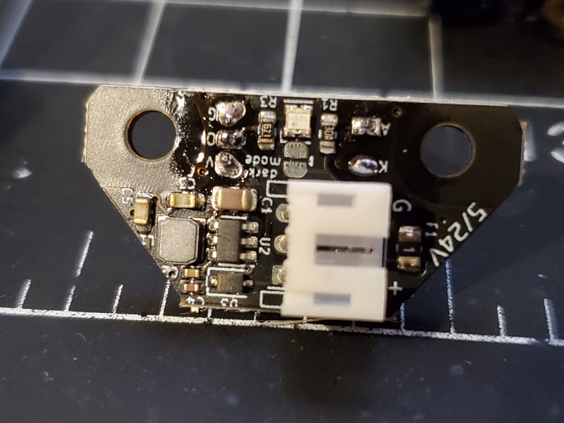
Something I need to check into before I set this up however is the default voltage setting for the rev 2.4.1 board (I'm not yet sure if it is set by default to accept 5v or 24v). Update - after re-reading the OptoTap info on GitHub, it sounds like the 2.4.1 is gonna use VCC (24v) by default, since it says the jumper was added to "allow for easy bypassing of voltage regulator circuit".
Step 4 - Stealthburner (subject to change, see Update)
My kit was was not an R2, so it has parts for the Afterburner tool head. I ordered the Stealthburner parts and am building it as a R2. Additionally, I am going to use a Rapido hotend (the regular non-HF for now). I can upgrade to the HF later, but that will require a new front panel and hot end assembly for the Rapido HF (since it's a bit longer).
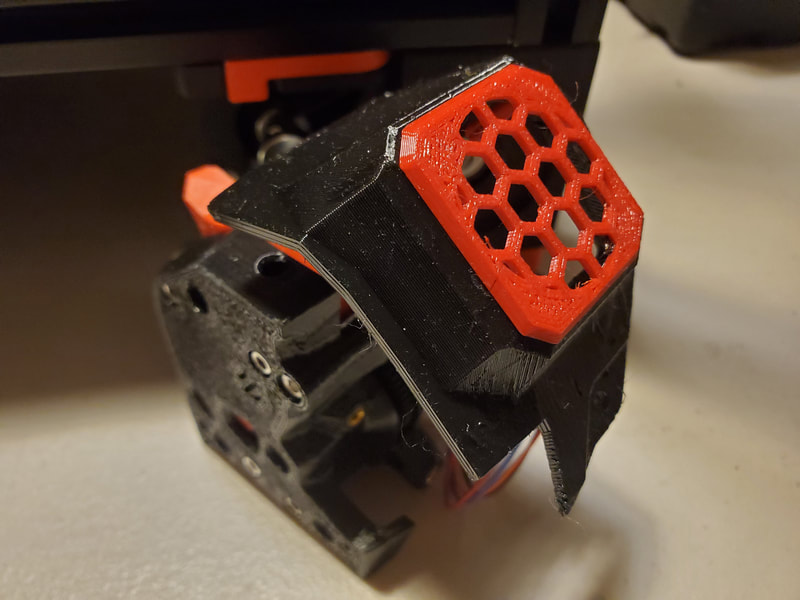
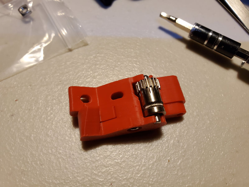
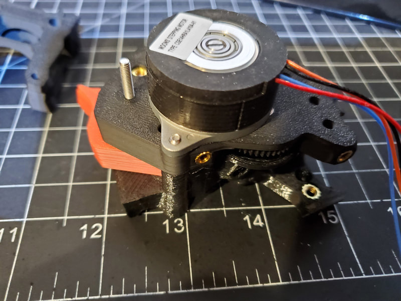
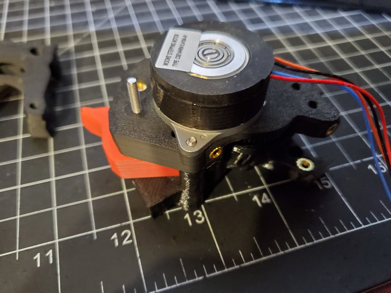
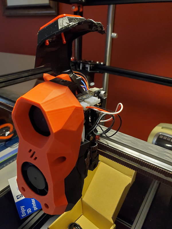
I had previously been working on adapting a Libra Mini Helical extruder for the Voron, however that design fell flat with issues and to top it off, I lost one of the helical gears. I see however that there are now helical gears for the Sherpa and even better, one with integrated helical gears (which I just ordered to use with the CW2). Integrated gears are what the cool kids are using, since they eliminate concentricity problems between the gear and the shaft (since the gear is machines as part of the shaft on an integrated gear). While I wait for the integrated helical gear, I'm building my CW2 with an upgraded POM gear, and some upgraded ball bearing fans (4010 axial and 5015 blower), since the stock kit fans are sleeve bearing.
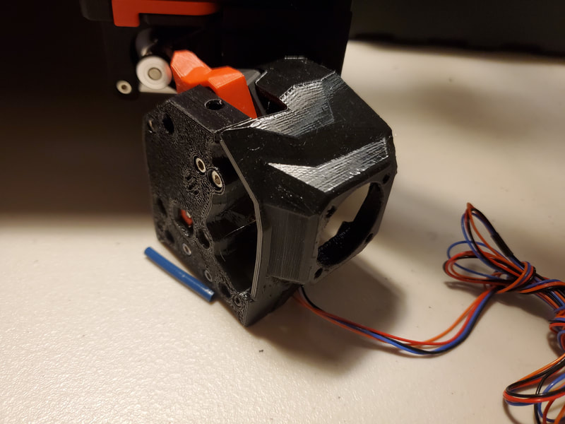
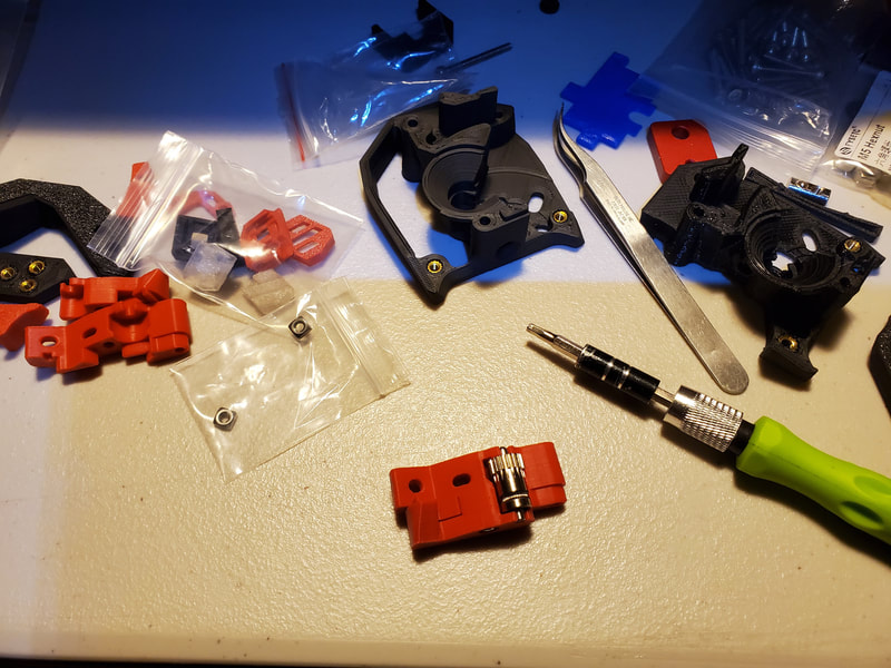
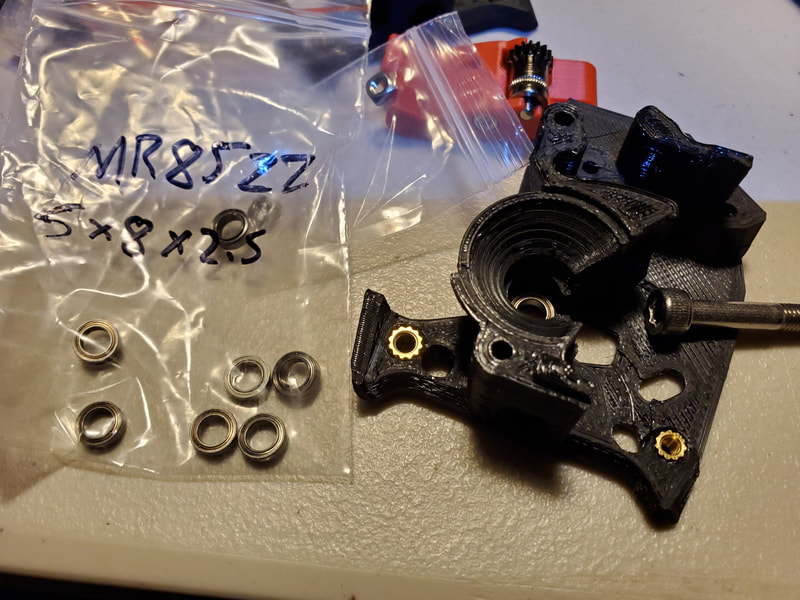
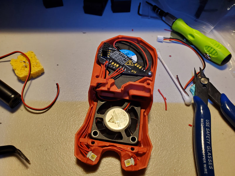
I didn't get many pics of the clockwork 2 setup, but the assembly went mostly like clockwork (pardon the pun). Since I was using my own printed parts for this (PETG), they are not as nice as the ones in the rest of the kit (that's on me). I'm going to reprint everything in ABS or ASA later though. I did not use the kit parts because I needed extra clearance for a FLY-SB2040 (version 1) and a 3007 fan to cool it and the stepper driver on that board (however I'm switching the SB2040 out for a BTT SB2209, which is explained below). The clockwork parts are from the design here (which I remixed to also work with the BTT SB2209 I will be using). The only things of note are that the black 50 tooth gear is an upgraded POM gear (which will be replaced with an integrated gear once I receive it), and I added some Superlube oil to the pin bearings which go inside the idler gear.
UPDATE - I recently learned that there is now a Fly SB-2040 Version 2, which uses a different 5V buck converter design. This makes sense as there is a thread mentioning that some folks have had serious issues with temps from the onboard temp sensor not registering correctly on the VMellow Fly SB-2040 Version 1 board. A high power drain (almost 0.8W at idle!) was also mentioned, with one person adding an external 5v buck converter and bypassing the internal 5v source to resolve some issues. I've decided not to continue with the SB-2040 Version 1 board at this time, and ordered a BTT EBB SB2209 which which I have installed using a remix'ed SB cover for easier access. I need to re-work this section but for now, I will leave the rest of the build log which includes the SB-2040 board info below.
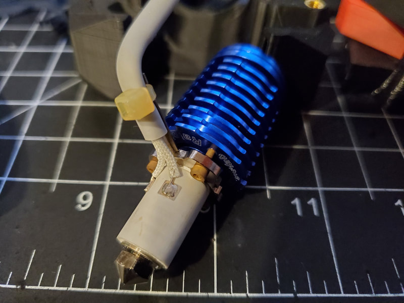
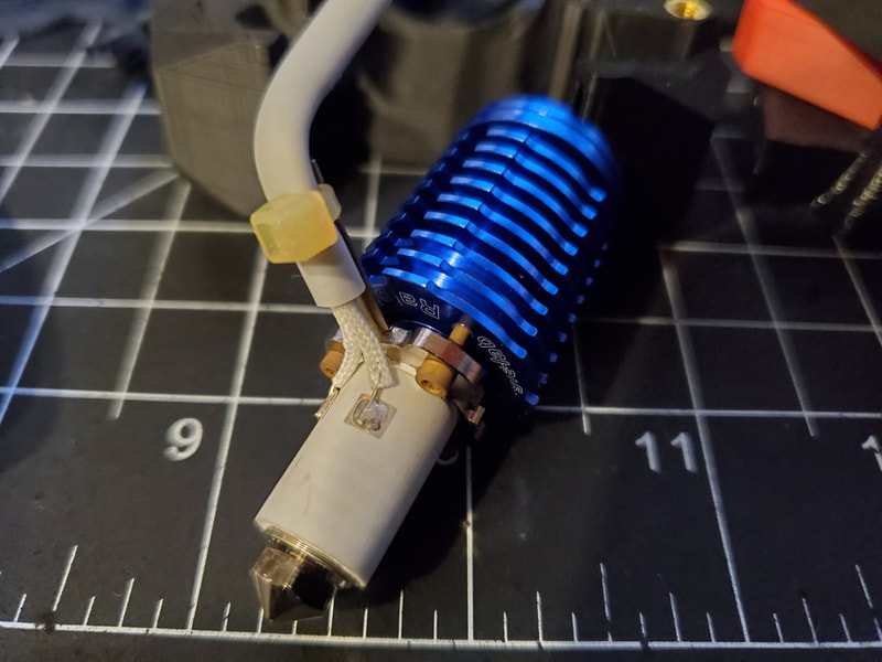
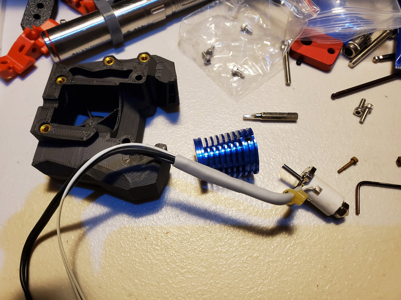
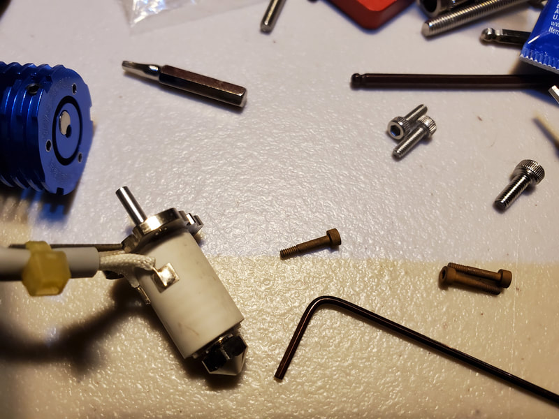
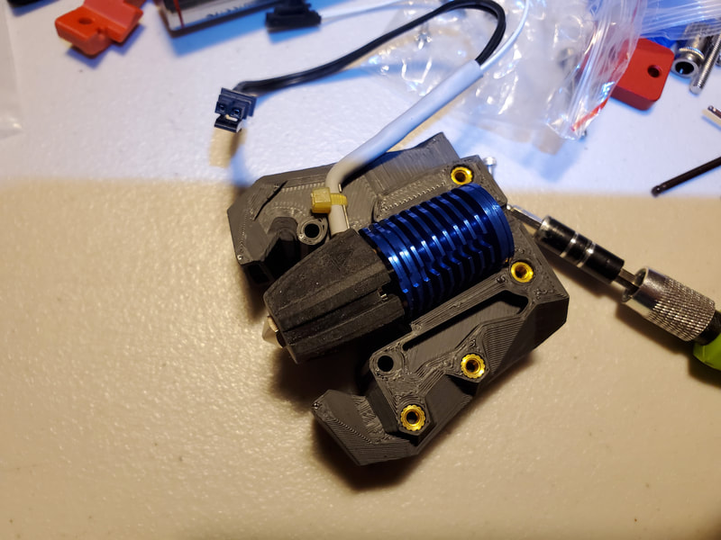
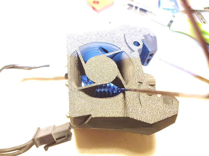
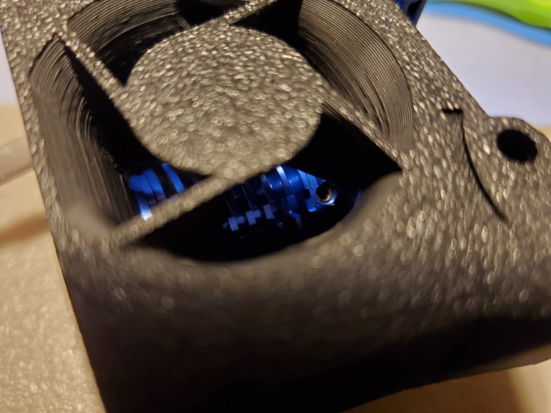
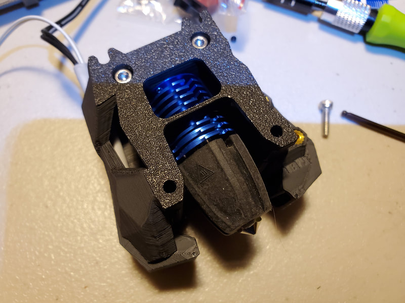
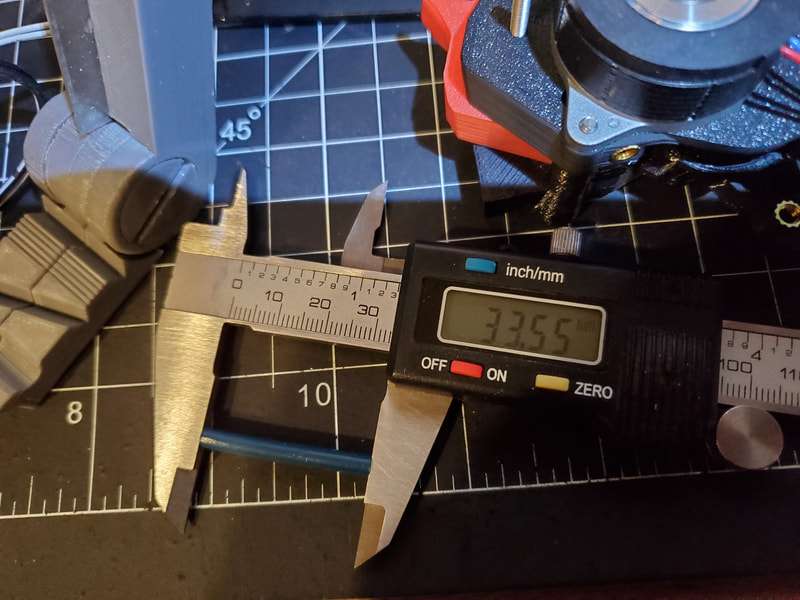
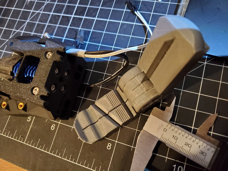
Next step was to build the hot end assembly. When I set up the Rapido hot end though, I ran into a minor problem. The Rapido required some disassembly to rotate the wires to where they could fit into the printed parts. This required removing three tiny titanium screws, loosening the grub screw which holds the heatbreak, then rotating the heatsink to where the mounting screws would line up, and the wires would also be correctly positioned, then re-assembling the whole thing. Something to note is that is that the grub screw will be accessible from the front when correctly installed, however it is a bit difficult to reach it (and the fan must be off to do so). The bowden tube was cut to 33.55mm, which left 11mm of it sticking out once installed into the Rapido. This is a great tool for getting square cuts on bowden tubes. One note on the Rapido, I ordered the UHF which shipped with both the HF and UHF setups, which is nice since I plan to start by using the HF and upgrade to the UHF later (I ordered mine months ago though, so check with the seller if you plan to go that route). The UHF will require a new front and other parts due to it's additional length, so I am not installing the UHF end yet. The Rapido HF will work with the stock cover, but requires a different hot end assembly than the default V6 setup.
Next step was to build the hot end assembly. When I set up the Rapido hot end though, I ran into a minor problem. The Rapido required some disassembly to rotate the wires to where they could fit into the printed parts. This required removing three tiny titanium screws, loosening the grub screw which holds the heatbreak, then rotating the heatsink to where the mounting screws would line up, and the wires would also be correctly positioned, then re-assembling the whole thing. Something to note is that is that the grub screw will be accessible from the front when correctly installed, however it is a bit difficult to reach it (and the fan must be off to do so). The bowden tube was cut to 33.55mm, which left 11mm of it sticking out once installed into the Rapido. This is a great tool for getting square cuts on bowden tubes. One note on the Rapido, I ordered the UHF which shipped with both the HF and UHF setups, which is nice since I plan to start by using the HF and upgrade to the UHF later (I ordered mine months ago though, so check with the seller if you plan to go that route). The UHF will require a new front and other parts due to it's additional length, so I am not installing the UHF end yet. The Rapido HF will work with the stock cover, but requires a different hot end assembly than the default V6 setup.
Next up is the final assembly of the Stealthburner, including the LEDs, fans (4010 axial and 5015 blower) and wiring up the Mellow Fly-SB-2040 board (which I later replaced with a BTT SB2209). The most difficult part of this was that, although pretty well documented, it looks like the Mellow docs are not as up to date as other info I have found regarding hooking up a Voron Tap.
The next two paragraphs below are depreciated since I swapped the Mellow SB2040 v1 out for a BTT SB2209, but I will leave it here for now, at least until I can re-write this for the SB2209 which I am using.
According to info I have read, if using the OctoTap v2.4.1 board, it was recommended (by Mellow's Aliexpress listing for the Fly SB-2040) to use the HV-endstop input (GPIO25) on the SB-2040 board. This, they said is due to the "endstop" inputs (GPIO 28 and 29) being max 3.3v. It's interesting that they did not say using GPIO 28 and 29 would fry the Pi2040, but they said that using those for the OptoTap board input, will cause incorrect temperature readings. In any case it's not a big deal as long as I know which pins to connect the OctoTap board to, and now I do (but their official docs do not yet have this updated info and still suggest connecting the OctoTap to GPIO28).
Another issue is that I want to add a small 3007 fan to cool the stepper driver on the SB-2040 using a modification of this model on Printables. According to info I've read, the Pi2040 chip and the TMC2209 chips on the SB-2040 can overheat, and adding a small fan resolves the issue. A heatsink is also a must on these chips, but the SB-2040 only includes one for the TMC2209 stepper driver chip. I have some small heatsinks I will add to the Pi2040 chip though, and will update here with the specs for that. The small 3007 fan however, will need to connect directly to the SB-2040, and there are no fan headers on this board (the fans are on the breakout board which attaches to the Stealthburner cover). There is however a set of pads labeled as "Fan 2", which is labeled as "5v / GPIO15 / VCC" in the docs. To connect the fan, I plan to solder the wires from the fan to these pads (in my case I will use a 24v fan, so will use VCC for the red wire and the black wire will go to the GPIO15 pin). This appears to be confirmed by info I found here also. I don't yet have my 3007 fan though (it's shipping from China) so it will be a while before I can test it out.
LEDs
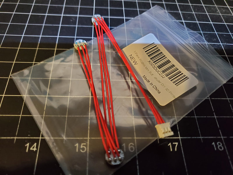
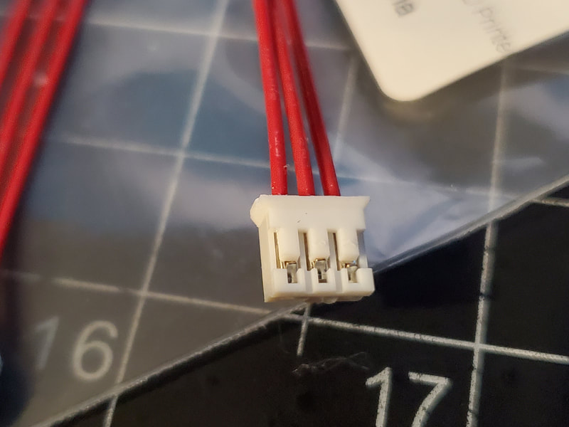
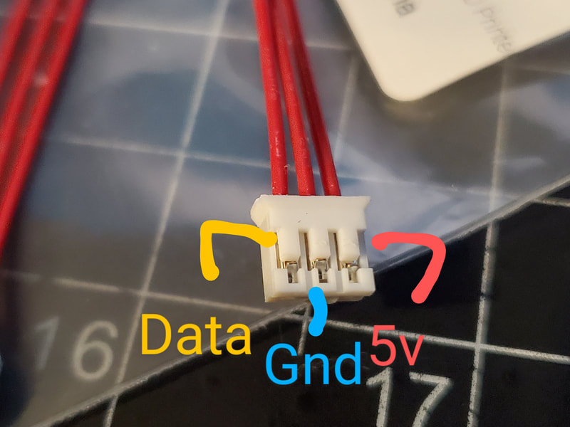
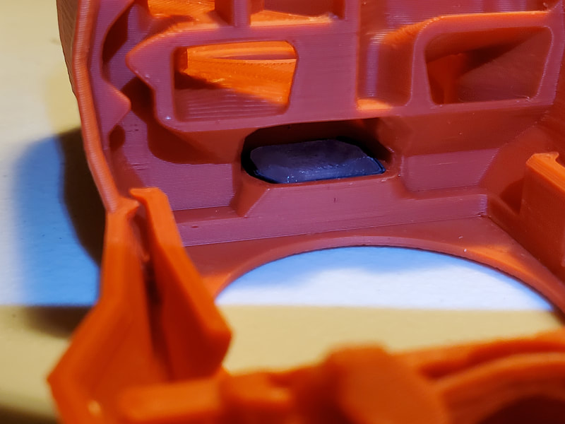
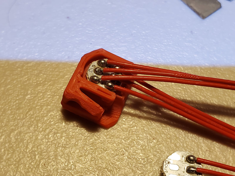
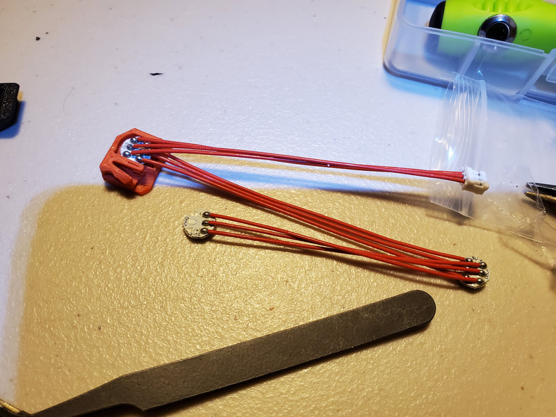
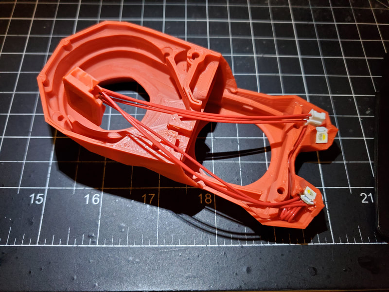
The first step to building the Stealthburner is to install the LED's. I bought these LEDs which of course are overpriced for what they are, and before I started, I traced the wires using my multimeter (set to ohms). I was looking to match up the pins on the connector to the last LED in the chain. By putting one lead of the meter on the pin of the connector, and the other end on the pad of the last LED in the chain of LEDs, it is possible to work out which pin connects to which line. This is very important to verify, since mixing up the pins can fry stuff. The pics below show how my connector was wired up.
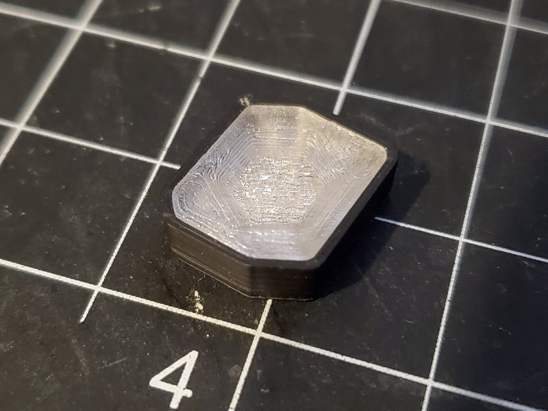
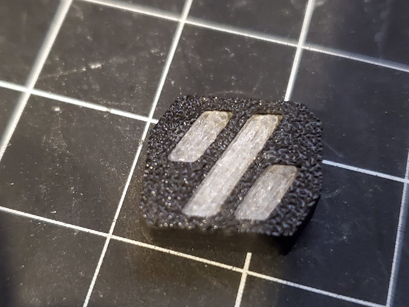
I also prepared the clear diffuser and the holder it goes into (which acts as a mask). I chose to use the black parts since this is not seen and black should block light better than the red parts which I was also sent. I found that this part required some sanding to get it to fit, so I would recommend doing that before trying to install it have having it get stuck halfway inserted. I also used some superglue to fix part of the mask which cracked. I suggest taking some time on this part to make sure it has smooth sanded sides and will slip into the pocket it goes in, without requiring too much force. Once it is sufficiently sanded, it must be pressed all the way down into the pocket (it needs to be fully seated of the part which carries the LED will not fit).
I also prepared the clear diffuser and the holder it goes into (which acts as a mask). I chose to use the black parts since this is not seen and black should block light better than the red parts which I was also sent. I found that this part required some sanding to get it to fit, so I would recommend doing that before trying to install it have having it get stuck halfway inserted. I also used some superglue to fix part of the mask which cracked. I suggest taking some time on this part to make sure it has smooth sanded sides and will slip into the pocket it goes in, without requiring too much force. Once it is sufficiently sanded, it must be pressed all the way down into the pocket (it needs to be fully seated of the part which carries the LED will not fit).
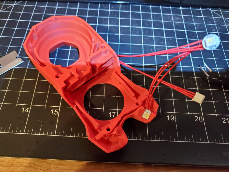
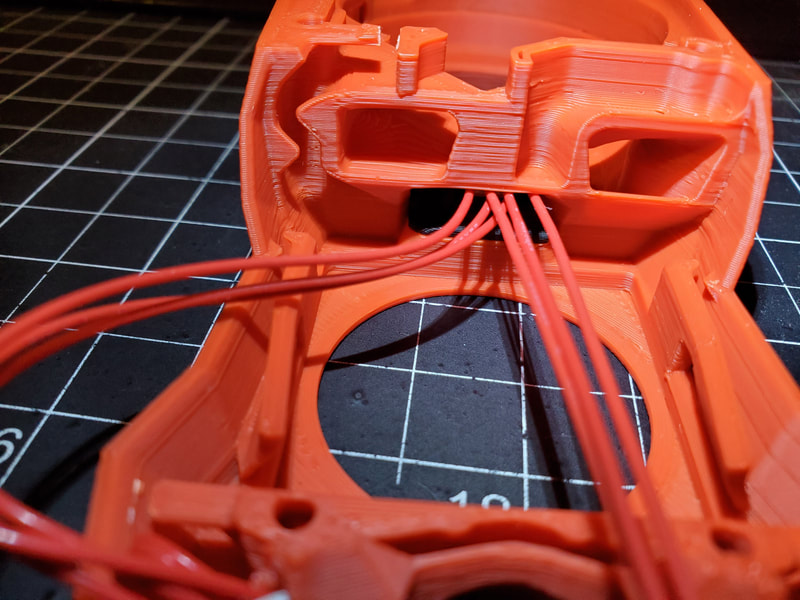
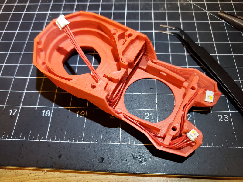
Next I just slid the first LED downstream from the connector into it's holder. Shown is the red holder, but I switched this to a black one to better mask out any wayward photons. Then, starting from the right side (facing up in the pics), the last LED at the end of the chain of of LEDs is installed and then the middle goes on the other side. The wires can be tucked into a channel between the LEDs, and a small (blunt) tweezers will help with tucking them in place.
The last LED goes into the pocket described earlier, and is a tight fit. It may require some sanding of the LED carrier to fit it in place, though mine did not. Once all the LED's are in place, the wires can be tucked in as shown in the pics below.
The last LED goes into the pocket described earlier, and is a tight fit. It may require some sanding of the LED carrier to fit it in place, though mine did not. Once all the LED's are in place, the wires can be tucked in as shown in the pics below.
Fans
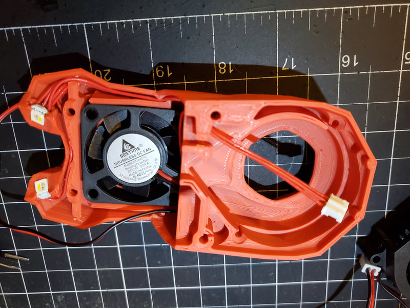
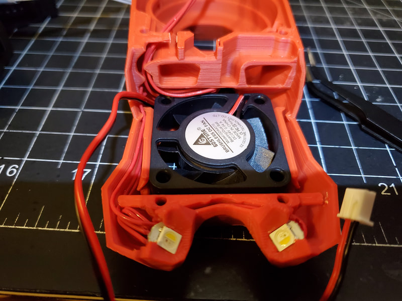
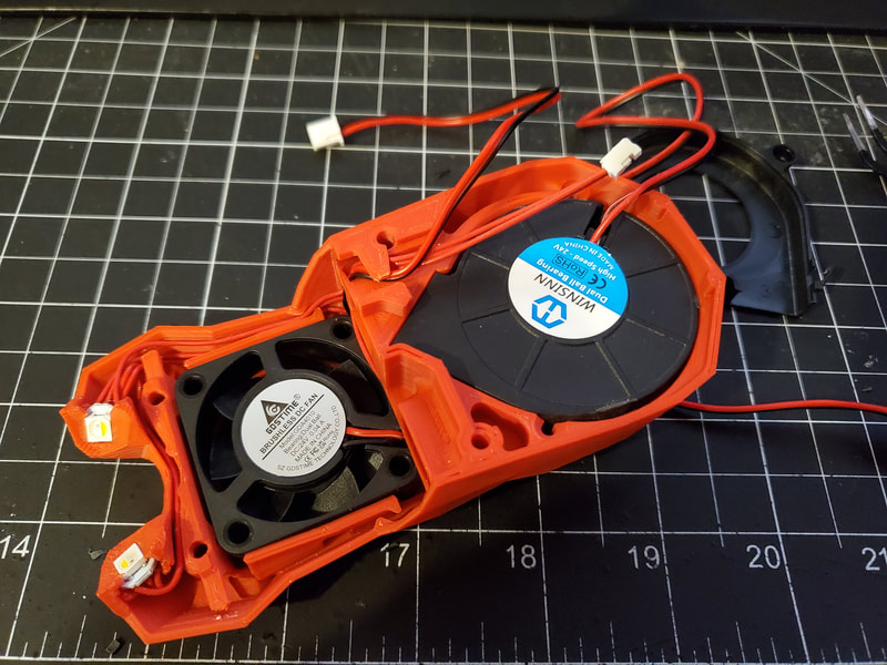
I upgraded the fans from the sleeve bearing fans in the kit. The Stealthburner requires a 4010 axial and 5015 blower. I already had some 5015 (24v) blowers from my CR10 toolhead so I used one of those, but I think any ball bearing fan would be a good upgrade (I have generally had good luck with fans from Sunon, GDSTime and WINSINN). The 4010 fan goes in pretty easily, though for cable management, I found that the wires had to go left right after the exited the cable clip on the fan (with the wires exiting the top). The manual says that the fan should blow inward, and some fans have arrows to say which way they will blow, but this one did not. Generally however, a fan will blow in the direction of the label, so that is how I mounted this fan. The wires just get tucked in and routed the same way as the LED wires. I made sure that the cover would close tightly with the hot end assembly after mounting the fan, if it did not, it meant there must be a wire that needs to be tucked in better.
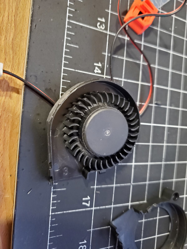
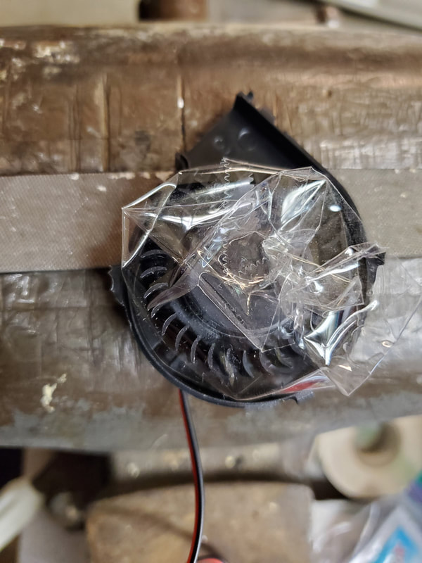
The 5015 blower requires some minor surgery before it can be fitted to the Stealthburner. My first suggestion though is to protect your eyes when doing this, I found that when I clipped the mounting tabs off the fan, the shards sprang away with a good deal of force. I'm getting slightly ahead of things though, since first the cover has to be removed. To do that I just used a razor to cut the tabs off. While I did that, I also cleaned up anything protruding from the fan body, such as the mounting tabs. Then I started to remove the tabs for mounting the fan with screws. These were first clipped (again protect your eyes if you do this), and then I protected the fan with some tape, lightly applied to the cage, and just filed down the remaining bumps. Give the fan a once over to make sure there are no protrusions and trim where needed, and then it just gets pressed into place.
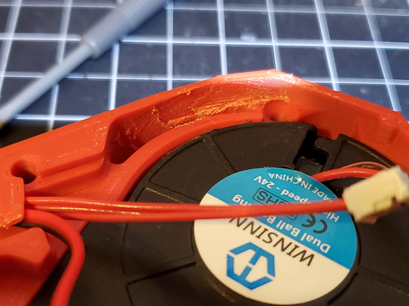
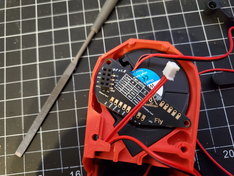
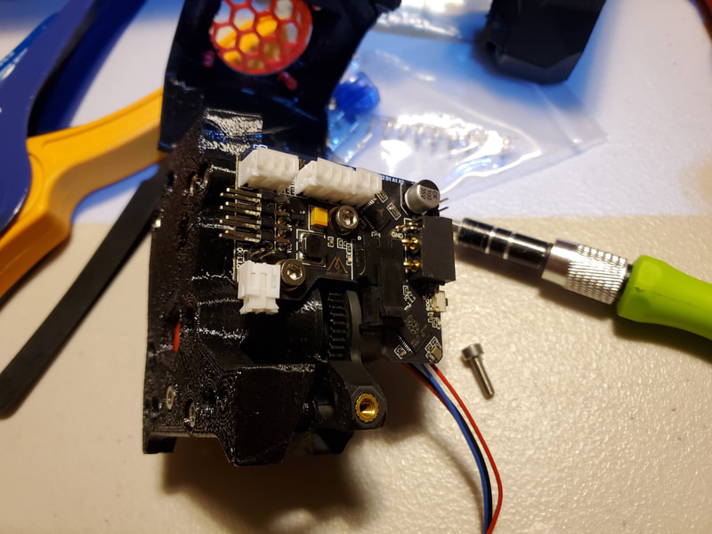
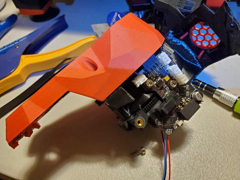
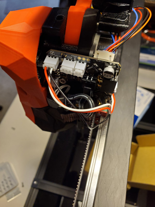
(Note this section is depreciated since I swapped to using a BTT SB2209) The Mellow Fly SB-2040 (version 1) board comes with a fan and LED breakout board, which mounts to the back of the 5015 fan. Some images I have seen of this board, show it with pins which are sharply bent at 90°, however mine did not ship with these pin headers. It may be more convenient to use the headers, but soldering the connectors will serve the same goal and may be more reliable. I found that I had to relieve the inside edge of the Stealthburner cover where it was touching the board, in order for the board to fit properly. I used the end of a small file to scrape the plastic away from the parts which interfered.
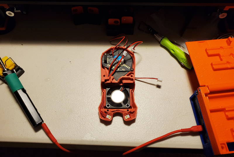
My soldering job on this was not my best work, but it should be good enough, and I used a microscope to confirm there were no tiny bridges. Since things are very tight, I did not give myself much slack in the wires and used some Rodico 6033 Cleaning Putty to help hold the wires in place while they were soldered. I am using 24v fans here, which are connected with the red wires to 24v (VCC) and the black wires connected to either GPIO13 (for the 5015 part cooling fan) or GPIO14 (for the 4010 hotend fan). 5v fans are also supported using different pins. The LED's were also soldered to the breakout board.
My soldering job on this was not my best work, but it should be good enough, and I used a microscope to confirm there were no tiny bridges. Since things are very tight, I did not give myself much slack in the wires and used some Rodico 6033 Cleaning Putty to help hold the wires in place while they were soldered. I am using 24v fans here, which are connected with the red wires to 24v (VCC) and the black wires connected to either GPIO13 (for the 5015 part cooling fan) or GPIO14 (for the 4010 hotend fan). 5v fans are also supported using different pins. The LED's were also soldered to the breakout board.
Now the fun part...
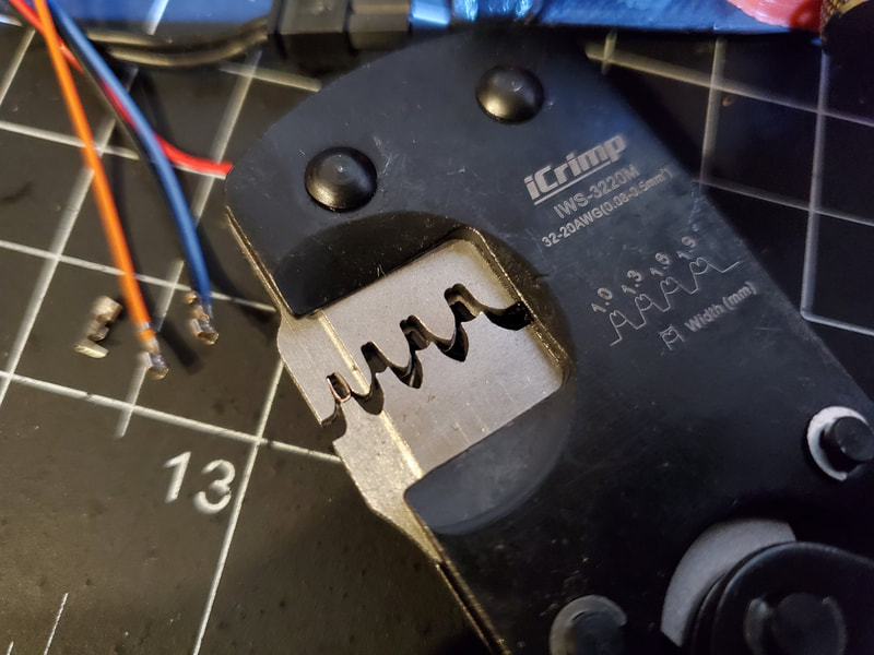
(Note this section is depreciated since I swapped to using a BTT SB2209) I was not looking forward to crimping these damn small connectors for the wires to the Mellow Fly SB-2040 (version 1) board. They include a bunch of spares and I needed every one since they are so small and fragile. I was happy however that I bought a new crimper specifically for the super tiny connectors, and it did a reasonably good job. No matter the crimper though, this is not a fun task. My only suggestion is to slightly bend the longer legs of the connector together and then place it in the correct position of the crimper (the smallest one in this case), and then bring the jaws together until they just hold the connector and latch in place. Then take the wire with just a couple mm stripped, and insert it into the connector (which should be secure in the crimper at this point). Check how deep the wire is set from both sides (a magnifier will help with this), and once it looks correctly positioned, where the larger legs will grab the insulation of the wire, and the smaller will grab the bare wire, give it a full crimp. The connectors usually got sort'a stuck in the tool at this point, but I just used a tweezers to push them out (don't pull them out by the wires of they may break). If the crimp did not get both legs fully, I would sometimes save it by adjusting the position and giving it another crimp, however if the connector was crushed it was time to start over.
I first connected the stepper, and had to locate the datasheet to ID the wire colors to what they did. Of course the Mellow SB-2040 datasheet uses A+, A-. B+, B- nomenclature for the stepper pins, and the datasheet uses A/C B/D, so I interpreted it as follows:
A+ Black Wire
A- Orange Wire
B+ Red Wire
B- Blue Wire
This is not yet tested, but it seemed like the best bet. I will probably need to rework the stepper wire since I left too much slack in it, but I will do that after everything is tested. I also had to crimp a new end to the thermistor, which is not polarized since it's essentially a resistor, but I left the stock heater connector for the Rapido in place (it is too long but will be shortened up once everything is tested). Finally the Voron Tap optical sensor was connected using a short jumper, and as noted before, it was connected to the "HV-Endstop" input, using 24v (VCC), Ground, and GPIO25 pins.
Once I get the 3007 fan for the cover, I will solder that to the pads on the top center using the set of pads labeled as "Fan 2", which are "5v / GPIO15 / VCC" in the docs.
The SB-2040 board was mounted using one M3x8 cap screw in the front and one M3x10 cap screw in the rear, with a printed standoff which is just a normal Voron part.
Electrical Bay
First a disclaimer, I am not an electrical engineer and you should do your own research and make your own choices when connecting up the electronics on any device, including a Voron printer. Working on electronics which use mains power is inherently risky and so if you choose to build a printer, it is at your own risk. Please do not use anything here as a guide or example, I am just showing what I did and adding some information on the parts I used.
In order to connect up the electronics, I referred to the manual and have also watched some youtube videos where folks have moved things around. After seeing other builds, I think the method of laying out the components in the manual is the way to go. Some considerations though are wire management and cooling of the stepper drivers. Wire management can be assisted by printing or buying some wire management guides. The cooling of the stepper drivers is something that should be kept in mind when placing the mainboard and any other items in the electronics bay, which would block airflow over the drivers.
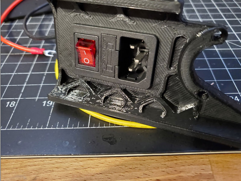
Before I started, I printed the power_inlet_IECGS_1mm.stl, which is the power inlet skirt which fits the power inlet that shipped with my FYSETC Voron 2.4 (R1) kit. Just a note, I found there are two versions of the standard IECGS power inlet skirts on the Voron Github, but I could find no explanation of what the difference is between them. When I compared them, I found they have slightly different dimensions (I used the "1mm" version for the switched inlet that shipped with the kit):
power_inlet_IECGS_1mm.stl which is 47.2 x 27.4 mm
power_inlet_IECGS_1.2mm.stl which is 48.2 x 28.0 mm
Once again a disclaimer - I am not an electrical expert or electrician, and am only showing how I am building my kit (which is still being built at the time of this post). Mains voltage is dangerous and deadly so if in doubt, consult an expert to make the required connections (which may even be required in your area). There may be changes. updates or variation in the FYSETC kits which could mean that parts, wire colors or connections are different that the switch inlet which I have, so always check your own work before connecting a switch or anything to mains power. Once the inlet switch inlet is wired up, it is especially important to test the it with a meter prior to making any connections to live power, and make sure that the hot/live wire and neutral wire are never shorted together (joined), regardless of the position (on or off) of the switch. I used the continuity function of my meter to test all the wires from the switch prior to connecting anything up to live power. Always triple check connections for high voltage (mains) wires and if in doubt, check the Voron docs or use community resources to find the answers.
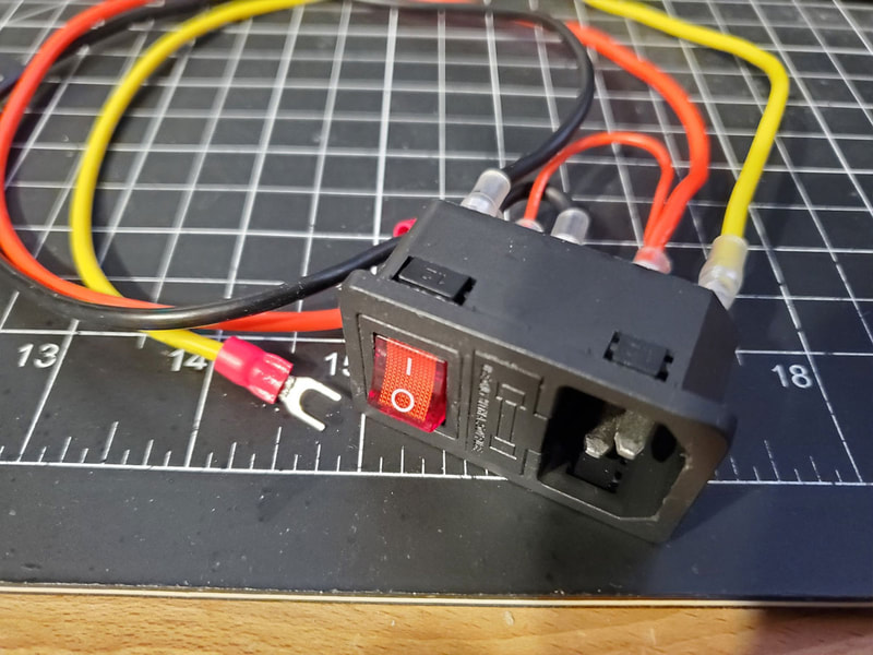
I may upgrade later to a filtered inlet, but for now I will use what's in the kit. The inlet which was sent with the FYSETC kit is pre-wired with the illuminated switch already pre-connected. However when I checked it closer, I noticed that it was not wired so that the double throw switch would connect or disconnect both the live and neutral at the same time, it was set up to only switch live. It's hard to see in the pics below, but there is a thinner red wire which is split off from the thicker red wire. The thinner wire which connects to the switch is only supplying a neutral connection so the switch can illuminate, it is doing nothing else, and the thicker red line from the inlet is going straight out without being switched. When I checked the docs, I see that the manual shows the power switch set up to toggle both the live and neutral wires, which seems safer, so will reconfigure the switch to do match the docs.
The pics below show the switch as received in the FYSETC kit, before I reconfigured it according to the Voron manual (pg 210 of the 2022-07-04 revision).
The other parts which I needed to set up the electronics are the mounts for the power supplies, as well as the mounts for the power supplies, and Raspberry Pi, those can be found at the Voron Github here. It's not pictured, but I had to slightly modify the power supply support bracket to better fit, since I ran the ducts behind the supply and the stock bracket did not provide enough space for the ducts.
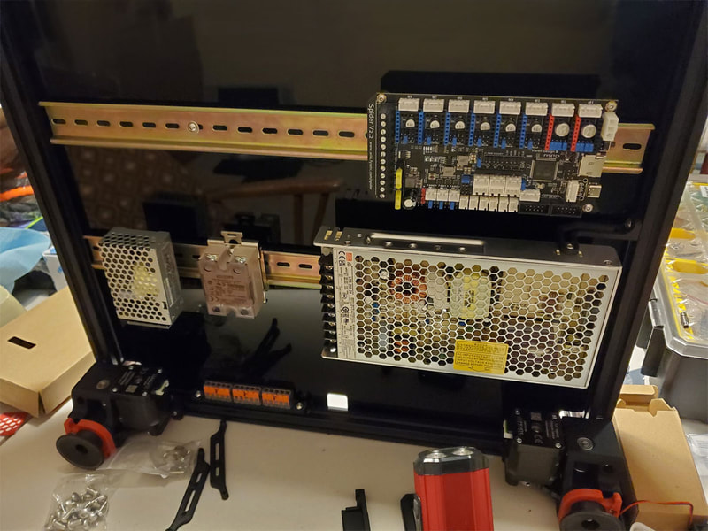
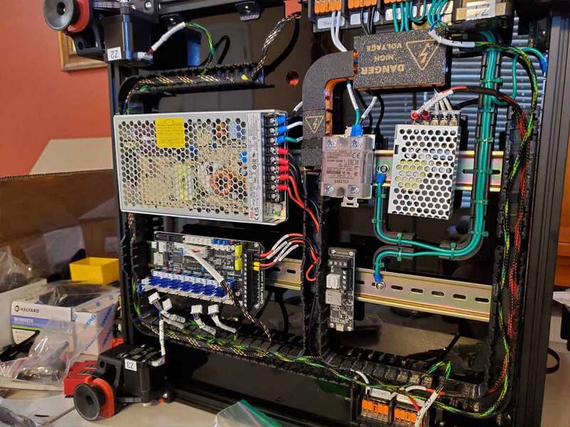
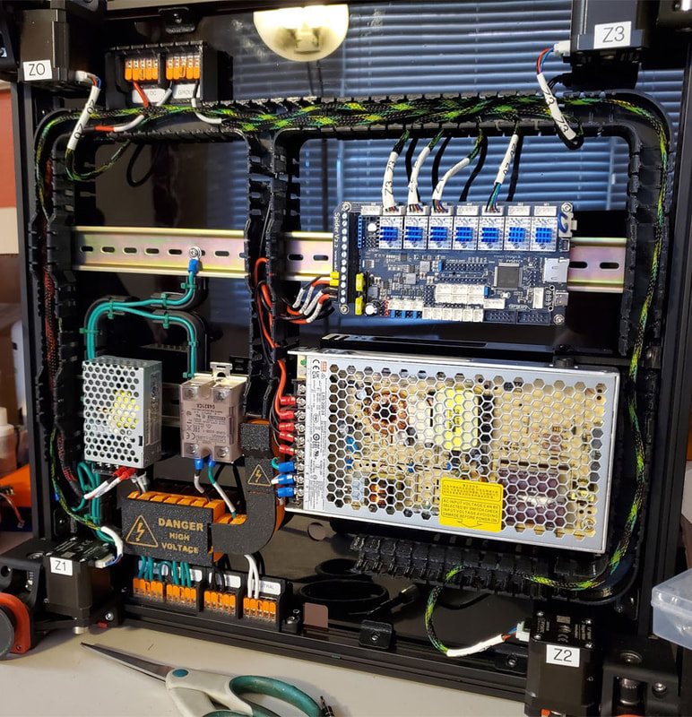
Once I had the basic printed parts ready, I installed the power supplies, the mainboard (Spider), and the SSR, which uses a metal DIN mount which shipped with the kit. I did not yet install the Pi, since I am working on a mount specific for it, which will allow me to leave it in a case and remove it easily for maintenance.
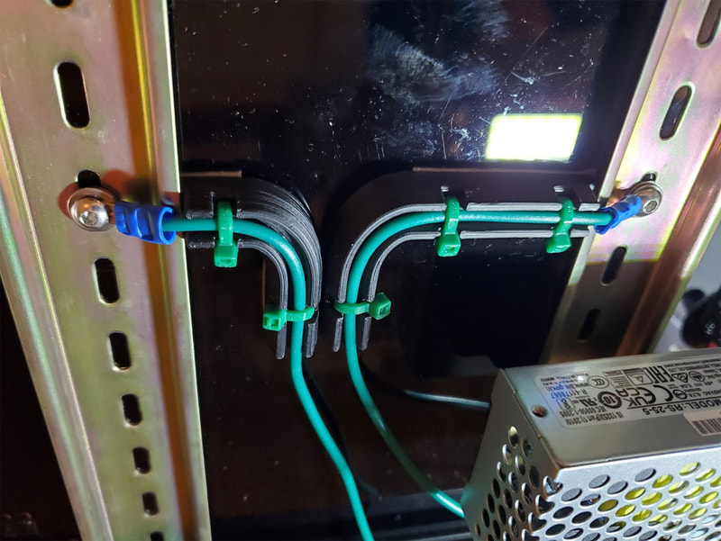
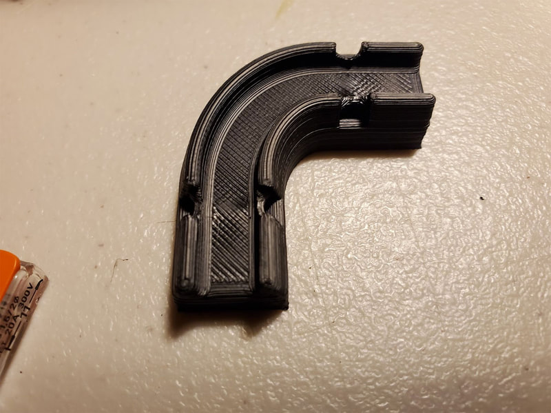
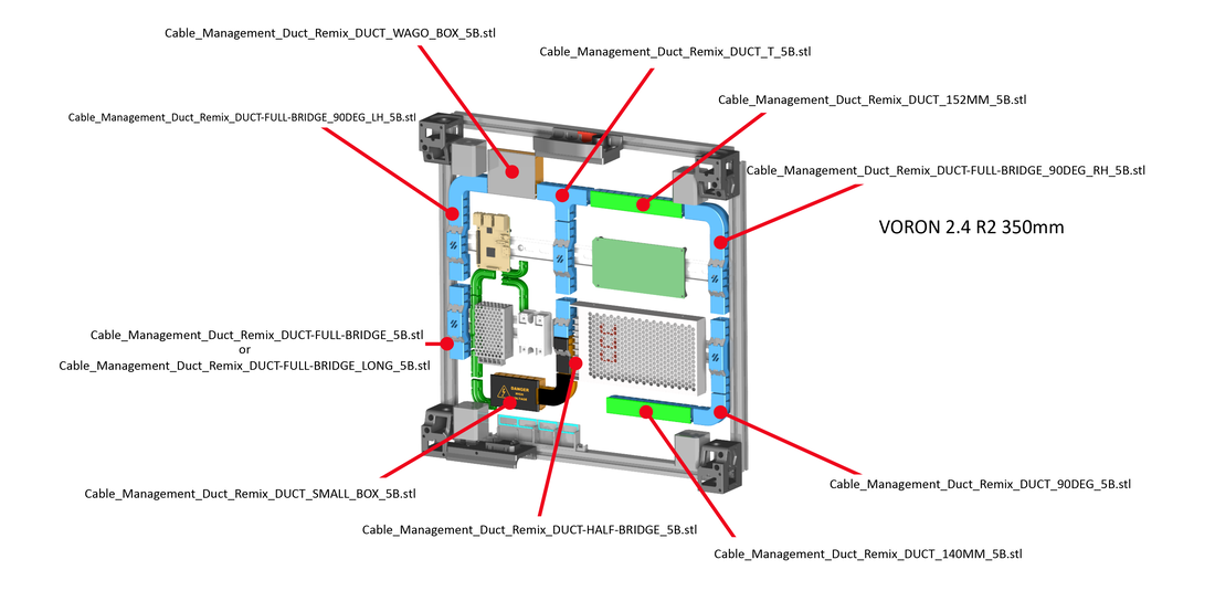
After several iterations of how best to keep the wire mess down, I found RyanDam's Cable Management Ducts (which are excellent). I remixed those ducts with some corner and bridge parts, which allow me to fully enclose the wiring and I think it makes for a tidy look. I also used some 4mm expandable PET sheathing on the stepper and other wires, to help keep them organized and protected inside the ducts. I used the following printed parts for my cable management:
The goals I had for the wire management were:
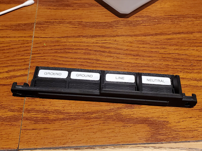
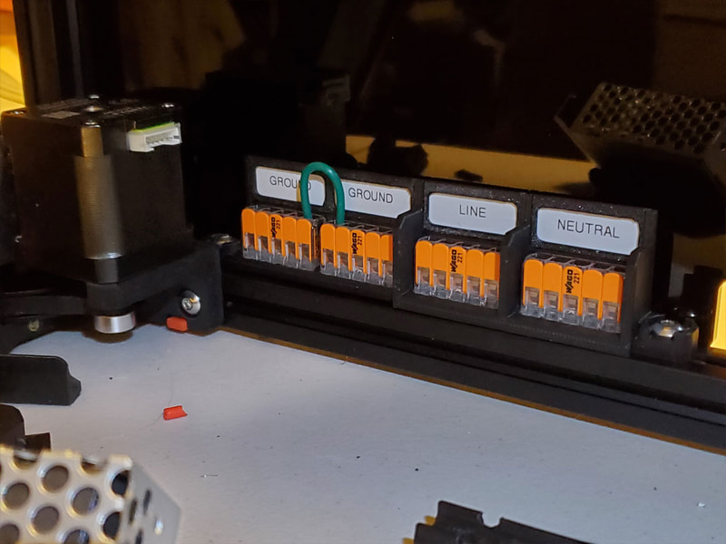
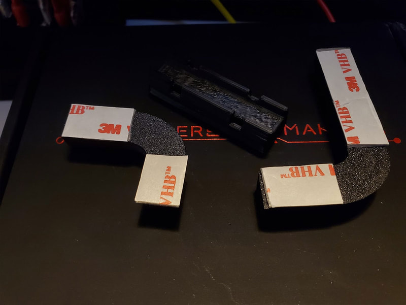
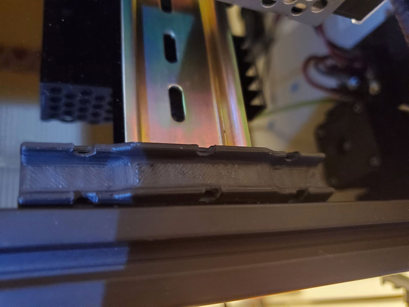
The first thing I did was grounded the wires. There are many ways to ground and I am not an expert on this - so I don't want to say this is the best way or the only way (please do your own research and make your own choice on how best to wire and ground your printer). Another option is to ground everything direct to the frame, and skip the Wago's altogether for the ground points. Since I went with the Wagos however, I found that there were not enough terminals in the largest 221-415 Wago connector, so I had to add a second. I used this Wago mount to add the additional Wago block for grounding. I grounded the following:
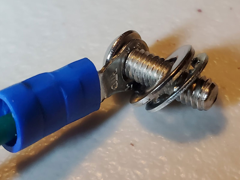
The grounding wires I used were 16 gauge silicone, and were managed using these guides. On the ground connections to the frame and DIN rail, used a star washer to help make a good connection, along with a washer over it. I used some Brother P-Touch 5.8mm heat shrink labels to tag the ground wires as well as any other single wires which I installed (tagged at both ends). My Brother PT-D610BT label printer worked perfectly for this, but other P-Touch printers should work as well.
- Wire management guides (I used these to manage the grounding wires)
- 5V DC Wago box, which I am using for 5V distribution
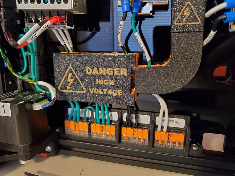
- AC Caution covers, which just have printed cautions for the ducts which will contain the high voltage AC wires.
- 221-415 Wago mount with labels. I used the version which holds four Wagos.
The goals I had for the wire management were:
- Ground the DIN rails and frame with as little mess as possible.
- Keep the AC and DC wires in separate ducts.
- Manage, protect and label the wires.
- Minimize the wire runs where possible.
The first thing I did was grounded the wires. There are many ways to ground and I am not an expert on this - so I don't want to say this is the best way or the only way (please do your own research and make your own choice on how best to wire and ground your printer). Another option is to ground everything direct to the frame, and skip the Wago's altogether for the ground points. Since I went with the Wagos however, I found that there were not enough terminals in the largest 221-415 Wago connector, so I had to add a second. I used this Wago mount to add the additional Wago block for grounding. I grounded the following:
- frame (with a star washer)
- SSR
- 24v Power Supply
- 5v Power Supply
- DIN rails (both of them using star washers)
- And of course, one connection goes back to the power inlet's ground wire.
The grounding wires I used were 16 gauge silicone, and were managed using these guides. On the ground connections to the frame and DIN rail, used a star washer to help make a good connection, along with a washer over it. I used some Brother P-Touch 5.8mm heat shrink labels to tag the ground wires as well as any other single wires which I installed (tagged at both ends). My Brother PT-D610BT label printer worked perfectly for this, but other P-Touch printers should work as well.
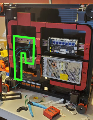
The routing I used for the ground wires can be seen in the picture below:
After the grounds were situated, I used a multimeter to check the resistance between the ground on the inlet to various points on the frame, to make sure things were connected without excessive resistance. I directly grounded both the DIN rails on my printer, even though there is no metal to metal connection on the upper rail, I think it still helps, since it provides a more direct path to the rails which mount the bed as well.
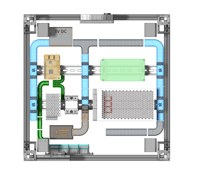
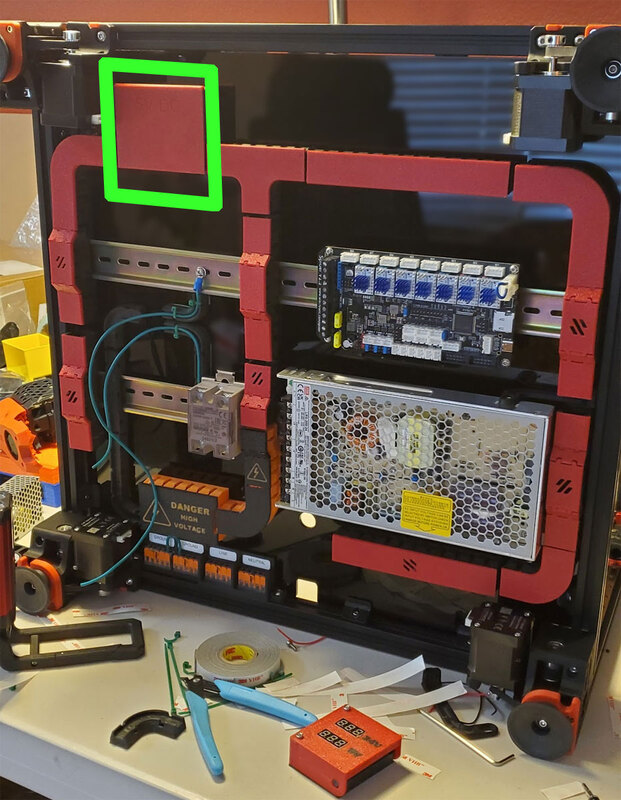
Next up, I printed and installed the cable management ducts. Below is a diagram of the parts used and where they went (all the parts are linked above):
Next up, I printed and installed the cable management ducts. Below is a diagram of the parts used and where they went (all the parts are linked above):
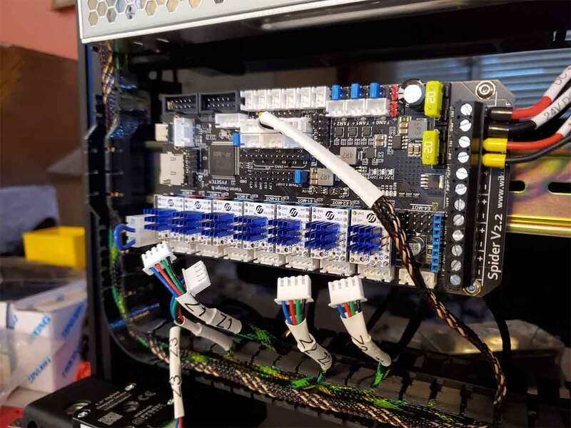
Since the stepper wires are all the same length, they either need to be wrapped up to take up the slack or cut down. After trying to wrap them and ending up stuffing the ducts full with the excess, I decided to cut them down. To do that I had to re-crimp the stepper wires using JST-XH crimp on connectors, which was a bit tedious, but also allowed me to put the 4mm sheathing and heat shrink labels on them (since the sheathing goes on easy with the stepper connector removed). Having the right tool when crimping tiny connectors really helps though, and the IWS-3220M is the best I have found for the money yet. I used Brother P-Touch 11.7mm heat shrink labels to seal the ends of the 4mm sheathing used on the stepper wires.
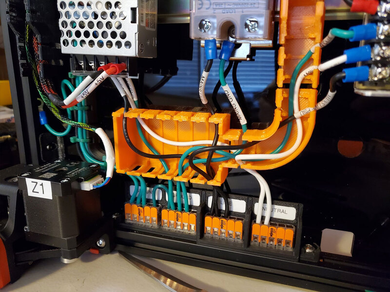
After the stepper wires were cut to length and finished, I also labeled the steppers themselves, then ran the stepper wires through the ducts, with a small loop at the ends so they could be unplugged if needed. The other wires were connected according to the Voron Manual, and labeled as well. I used wire ferrules where connections had to be made into screw down terminals on the boards, and either spade or ring connectors where connections were made to the power supplies and the SSR. Note that the pics below were showing things as I was working on the wiring, and taken a couple months ago (when I had time to work on the printer). Some things have changed since then, but the pictures illustrate how the wiring was configured.
After the stepper wires were cut to length and finished, I also labeled the steppers themselves, then ran the stepper wires through the ducts, with a small loop at the ends so they could be unplugged if needed. The other wires were connected according to the Voron Manual, and labeled as well. I used wire ferrules where connections had to be made into screw down terminals on the boards, and either spade or ring connectors where connections were made to the power supplies and the SSR. Note that the pics below were showing things as I was working on the wiring, and taken a couple months ago (when I had time to work on the printer). Some things have changed since then, but the pictures illustrate how the wiring was configured.
As can sort'a be seen in the above pics, the AC wires were also labeled and run similarly. However the AC wires are confined to the orange and black ducts, so they are separate from the low voltage wires. I used ring terminals where possible on the AC wire connections to the power supplies and the SSR. For the AC stuff I used 16 gauge silicone wire.
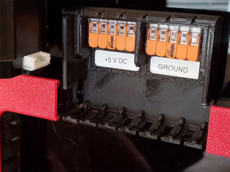
The low voltage DC wiring was not fully completed when I had to pause the project (so the pics do not show the wiring finalized). The only noteworthy points for the DC wiring are that I'm using a box for 5V distribution, and I'm going to add some DIN fuses on the 24V DC in lines to the CANBus board. The DIN fuses are not yet installed, but they just mount to the DIN rails. The 5V distribution box is designed with two 5 port WAGO's and resides near the front left of the printer. That location was chosen to reduce the wire runs to the 5V components (such as the Pi). If there is room, I may fuse the 5v lines using the DIN rail fuses as well.
That is pretty much all there is to this point. I have a couple other designs which are mostly done, and will be added here, once I get them installed. One is a simple voltmeter which will display the 5v and 24v voltages, it's not really very practical though, since it is only viewable when the base is opened for maintenance, but it could have other uses so I still may post it. The other is a Pi Panel which will mount to the front and extend the USB, SD and some LED's to the front of the printer, which should make maintaining the Pi much simpler. The Pi Panel design is released at the request of some folks who expressed interest even though it's not tested.
Once I get back to building the Voron (should be soon), I will update this further.
Once I get back to building the Voron (should be soon), I will update this further.
Just Some Notes and Other Stuff
I had considered adding a circuit breaker to the DIN rails, however there is limited room, and since the inlet is fused they should not be needed. However, I am planning to use a GFCI plug on the printer power cable (external to the printer). I may add a DIN mounted latching relay or possibly an external relay box (like the IoT relay), so I can have another way to shut it off (which would utilize a smoke detector and maybe temp sensor). Finally, I may add a small powered USB hub somewhere to connect up the webcams, so I won't need to have them fed through the Pi (though if it too tight I will just skip that).
This was last updated on 8/13/2023.
This was last updated on 8/13/2023.
