Notes on upgrading an AnyCubic I3 Mega with TMC2208 Drivers and a BL-Touch V3.1
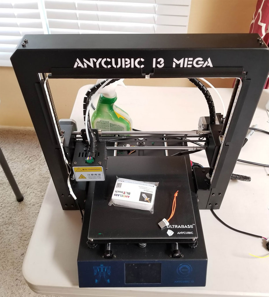
These are my notes for my own recollection on how to upgrade an Anycubic I3 Mega. It is not a guide, but if it saves you time great - but as always check everyting for yourself, this is as-is and at your own risk if you brick your printer or worse (though I have never seen a printer bricked yet due to firmware upgrades). This is not going into the nity-gritty details since I want to keep it condensed as much as possible. This is based on info from various places and most importantly the video that Ted Marozzi shared on how he upgraded his printer:
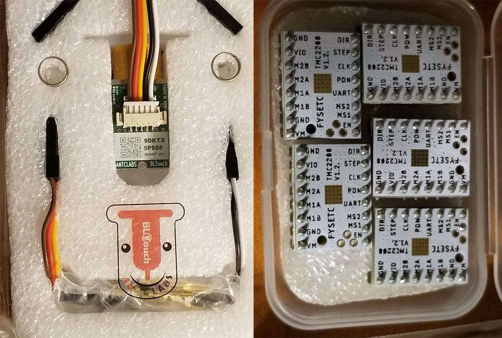
This is what I have and the upgrades I plan to do:
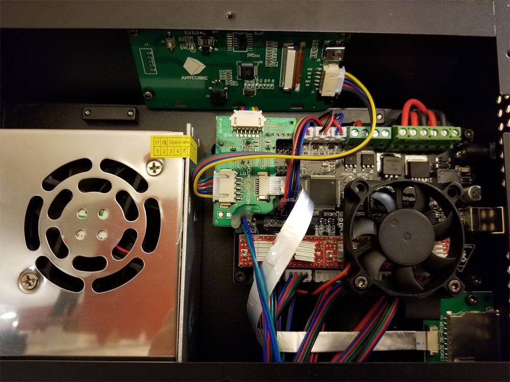
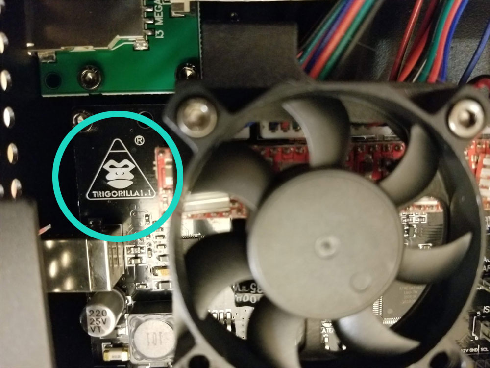
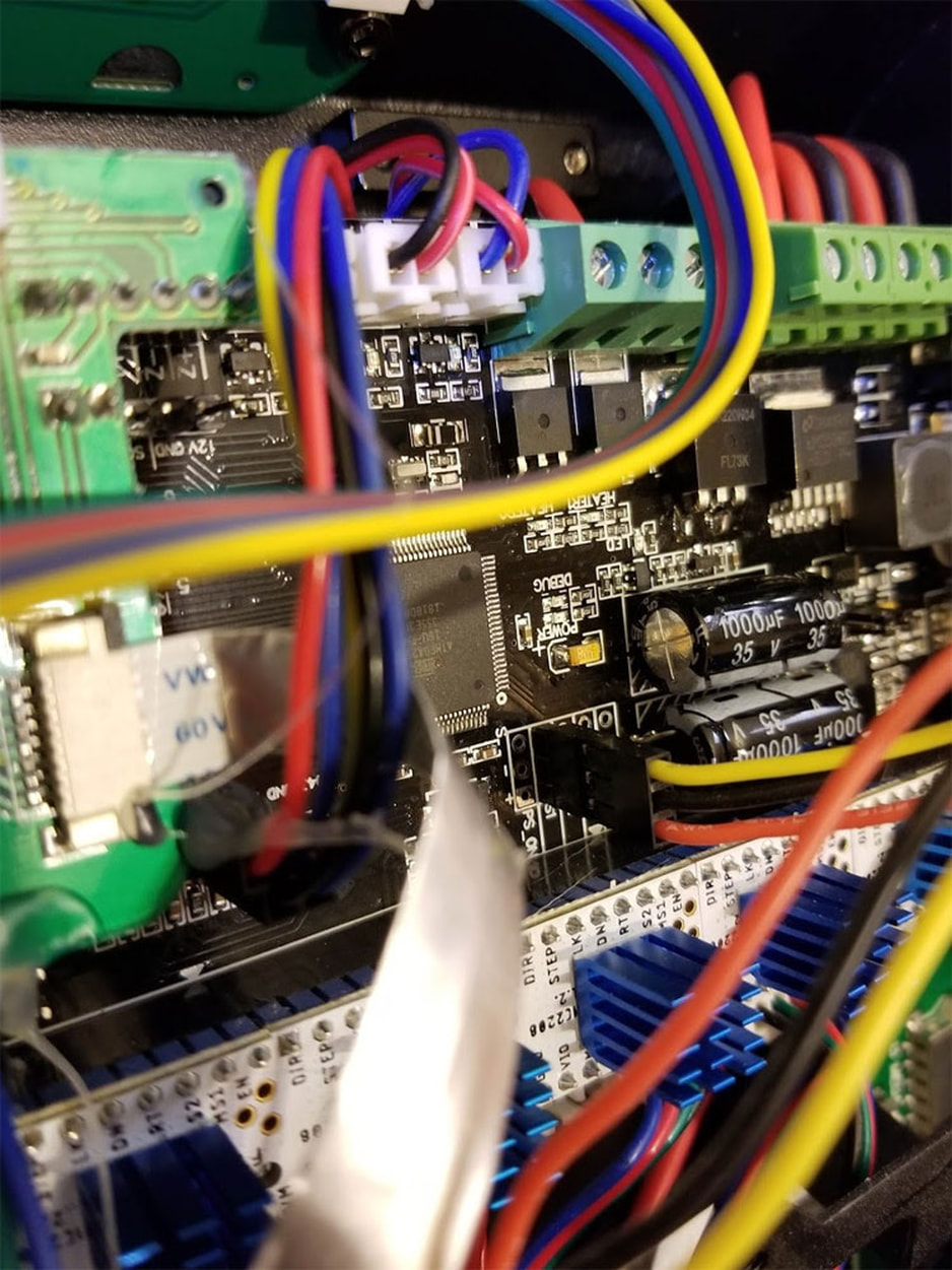
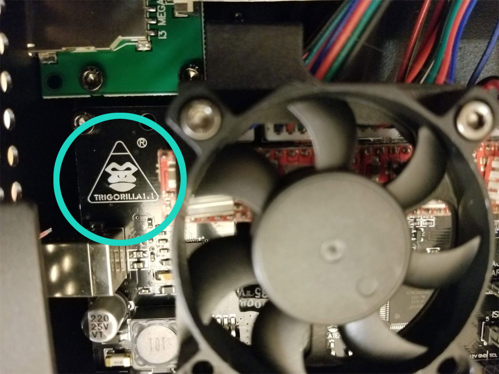
Tri-Gorilla Board V1.1 (see pics below)
Upgrades:
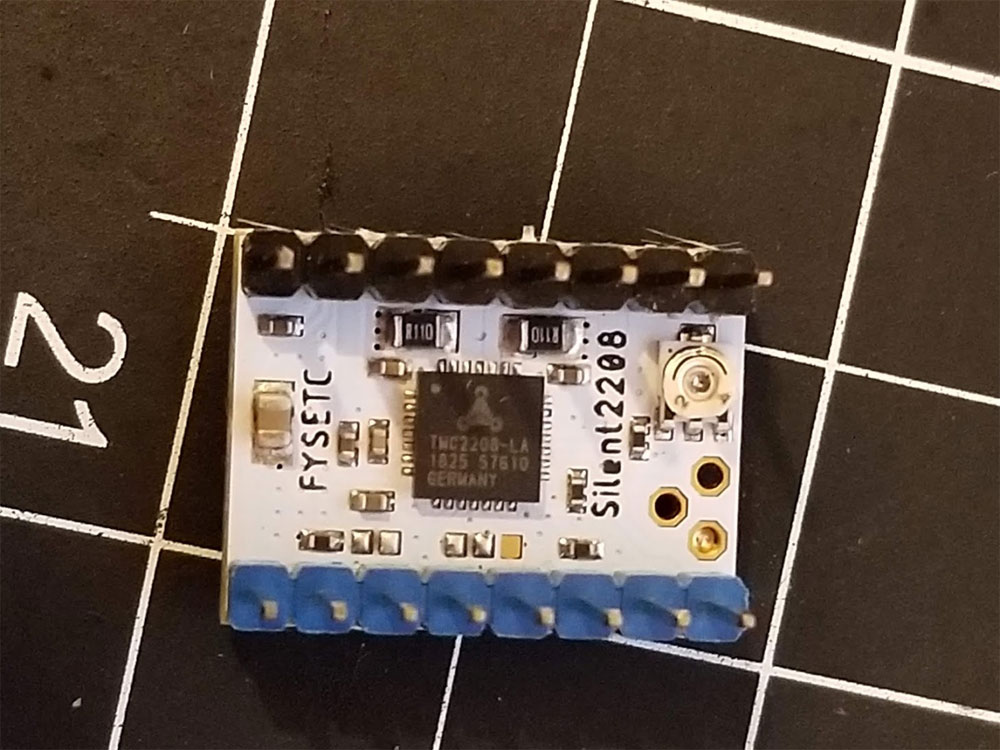
1. TMC 2208 Stepper Drivers x,y,z,e
2. Antclabls BLtouch V3.1
According to the video, the I3 will loose it's dual z-endstops, and there is really no way around this since it will not have any Z-endstops after the BL Touch is installed. They could probably be moved to the top as z-max endstops and serve the same function, but for simplicity sake the dual Z endstops will be dropped from this printer due to the upgrade. All the parts were provided by a buddy who picked them up a while ago. The BL Touch is genuine and the TMC2208's are from Ebay I think. In any case it all is new stuff.
TMC2208 notes:
I'm going to install the TMC2208's in standalone mode (they will not have UART control). This is just easier, but if there is a problem on the extruder, I will just revert it back to the A4998 driver there.
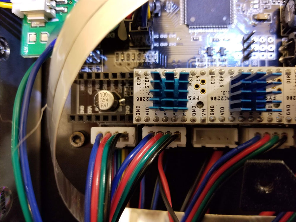
The biggest gotcha here is the orientation of the TMC2208 steppers (thanks to HansvG and Juha_J at Thingiverse.com for posting about it and pics with the correct orientation of the drivers). You can read the details here. The drivers need to be install in the correct orientation or it could fry things as noted in the link. To confirm the orientation is correct, the GND and DIR pins are going to the same place as they were with the old drivers. Installing them backwards will fry something.
The 2nd gotcha is that the stepper outputs may need to be reversed from the stock A4998 (apparently some drivers don't need the direction flipped and some do). This can be done in hardware (flipping pins on the connectors) or software by editing the configuration.h in Marlin. I'm doing it using the config method.
The Vref I will use as a starting point will be the following (thanks to Dai Hai Zu's video here.
X = 0.9V
Y = 1.2V
Z = 1.1V
E = 1.1V
"TMC2208 Marlin setup:
I initially tried to start off with Marlin 2.0 but had issues (later I determined them to be either a hole in space time or some faries were stuck in the printer causing havoc). I also found a compile error in the release version so maybe try the bugfix (error was #define E0_AUTO_FAN_PIN TRIGORILLA_FAN2_PIN which needed to be changed to #define E0_AUTO_FAN_PIN TG_FAN2_PIN ). The TMC drivers were no problem, but the BLTouch was nothing but. In any case I fell back on DavidRamiro's Marlin-Ai3M-2.0.x-2.0.x code here. I then brought that into ArduinoIDE and made some edits or checks.
Below is a summary of things to check/change - specific to the TMC2208 part of this upgrade - and the I3 itself.
configuration.h
#define MOTHERBOARD BOARD_TRIGORILLA_14_11 // since I am using a V1.1 tri-gorilla which has the servo pins mapped differently from the prior version.
// The following were also modified to correct the stepper directions and configure the steppers (really only need the X, Y, Z, Z2 and E0 but does not hurt to add them all). Note that I upgraded all the stepper drivers to TMC2208 (flytech):
#define X_DRIVER_TYPE TMC2208_STANDALONE
#define Y_DRIVER_TYPE TMC2208_STANDALONE
#define Z_DRIVER_TYPE TMC2208_STANDALONE
#define X2_DRIVER_TYPE TMC2208_STANDALONE
#define Y2_DRIVER_TYPE TMC2208_STANDALONE
#define Z2_DRIVER_TYPE TMC2208_STANDALONE
#define Z3_DRIVER_TYPE TMC2208_STANDALONE
#define Z4_DRIVER_TYPE TMC2208_STANDALONE
#define E0_DRIVER_TYPE TMC2208_STANDALONE
#define E1_DRIVER_TYPE TMC2208_STANDALONE
#define E2_DRIVER_TYPE TMC2208_STANDALONE
#define E3_DRIVER_TYPE TMC2208_STANDALONE
#define E4_DRIVER_TYPE TMC2208_STANDALONE
//#define E5_DRIVER_TYPE A4988
//#define E6_DRIVER_TYPE A4988
//#define E7_DRIVER_TYPE A4988
// Directions may or may not need to be changed depending on the driver, for the FYSETC TMC2208 drivers, these worked:
#define INVERT_X_DIR false
#define INVERT_Y_DIR true
#define INVERT_Z_DIR true
#define INVERT_E0_DIR true
configuration_adv.h
#define NUM_Z_STEPPER_DRIVERS 2 // This is required since the I3 has dual Z Steppers
BL Touch Notes
I went with the method of replacing the Z-MIN endstop with the BLTouch since that is the simplest and required no soldering, just a bunch of crimping connectors. This method means that the dual z-endstops will be given up in place of one BL-Touch. This will follow the guide in the video here by Ted Marozzi.
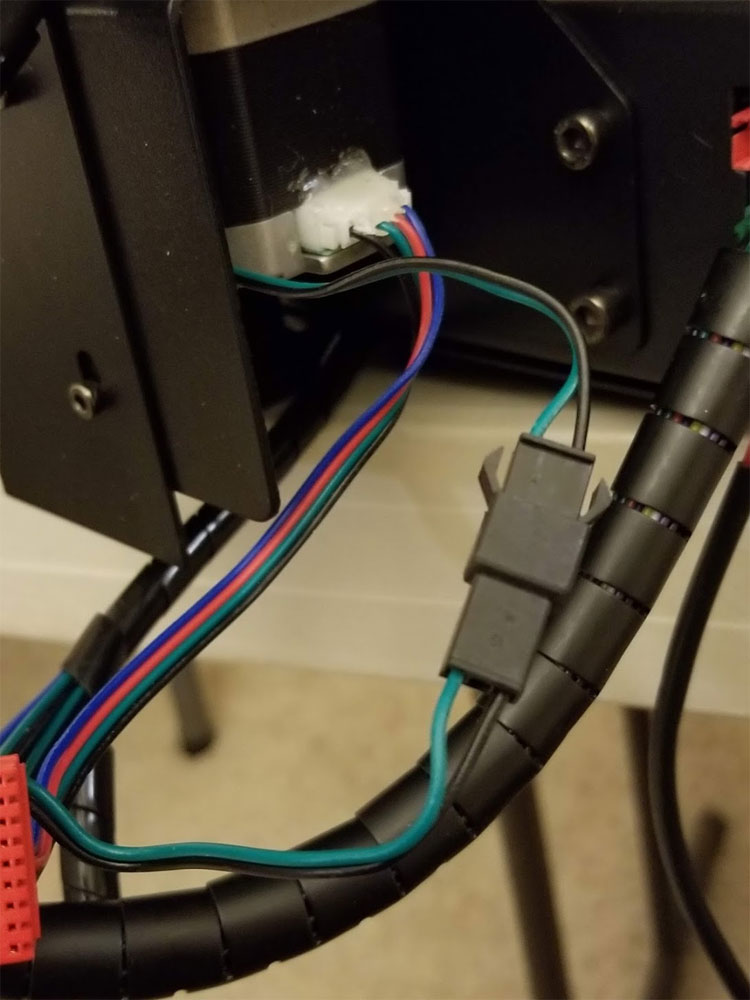
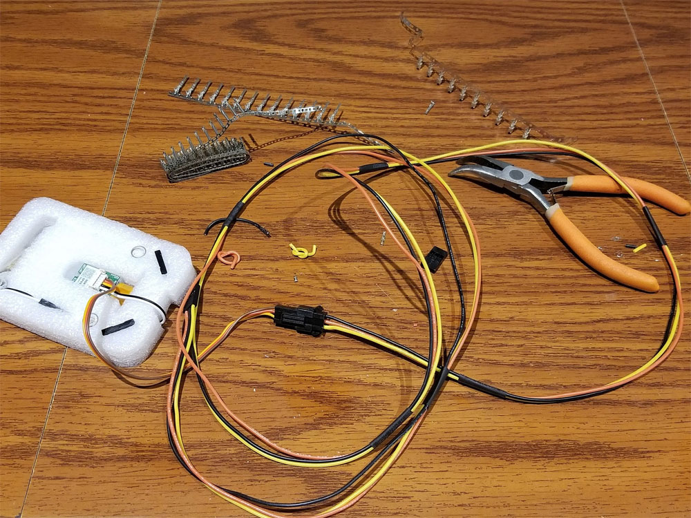
In the pics below you can see where and how the servo pins were connected to the board and also how a connector was added on the z-min endstop to allow me to revert things if I wanted to. The important things to note are that only the Z-min endstop will be used now (the other z endstop is disabled in firmware later), and that the board here is a Trigorilla v1.1 and that has the servo pins re-mapped from earlier versions (which just means that the correct board needs to be chosen in Marlin). Also the sensor is a Antclabs BLTouch v3.1. It is hard to tell on the pics, but the wire harness I made has Yellow (signal), Red (+5V) and black (Ground) which connect to the corresponding pins on the BLTouch. Not shown is the while and black wire harness which connects white and black from the BLTouch to the green and black (respectively) on the wires that go into the printer from the z-min endstop (this is the one on the right / connector side of the printer).
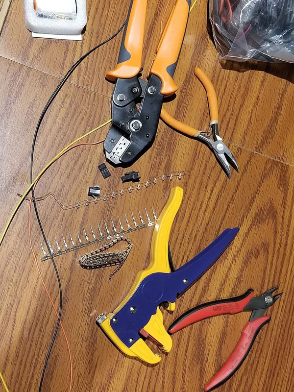
I used a lot of latching connectors, though I don't recall the type. I'd recommend getting latching connectors since the duponts generally suck except for wires that never move.
BL Touch v3.1 Marlin Setup
I had a few questions on the BLTouch v3.1. I tend to steer clear the BLTouch due to the myriad of problems they seem to have with various boards, and the 3D Touch probes just work. The Docs also seem to be less than great when it comes to clarity and just making sense. In any case, I did not have a choice here so I just rolled with it. My primary question was the switching mode for 3.3 and 5.0v operation in the probe (since for the TriGorilla v1.1 it would use 5v). I was not sure if I should just set the #define BLTOUCH_SET_5V_MODE in configuration_adv.h, though it seems like it would be the way to go. The ANTCLab docs show it is commented out, though in the course of troubleshooting I did enable that, so not sure if that sets it to 5V in eeprom or not, but it works (that was not the fix though). I may remove it again from the working firmware and see how it goes but a bit worn out now with messing with it.
The process of getting the BLTouch working almost made me question my sanity and I was close to breaking out my cheap mini-o-scope to monitor the signal pin since it would not deploy. I even tested with a spare 3D Touch probe to make sure I did not have a bad sensor. Long story short, no idea what it was eventually, but I double checked the cable end to end back to the board and all was good, and the re-flashed it (for the 20th time) and has been solid since.
Below is a summary of things to check/change - specific to the BLTouch part of this upgrade and is part of the current working firmware I am using - again, based on DavidRamiro's Marlin-Ai3M-2.0.x-2.0.x code here, as well as the video here by Ted Marozzi.
configuration.h
#define BLTOUCH
#define NOZZLE_TO_PROBE_OFFSET { -1, -24, -2 } // using one similar to this https://www.thingiverse.com/thing:2824005
#define AUTO_BED_LEVELING_BILINEAR
#define GRID_MAX_POINTS_X 6
#define MIN_PROBE_EDGE 10
#define USE_ZMIN_PLUG
#define ENDSTOPPULLUPS
#define ENDSTOPPULLUP_ZMIN_PROBE //Redundant, but won't hurt
#define Z_MIN_ENDSTOP_INVERTING true
#define Z_MIN_PROBE_ENDSTOP_INVERTING true
#define Z_MIN_PROBE_USES_Z_MIN_ENDSTOP_PIN
#define Z_SAFE_HOMING
#define Z_PROBE_SPEED_FAST HOMING_FEEDRATE_Z
#define Z_CLEARANCE_DEPLOY_PROBE 10 // Z Clearance for Deploy/Stow
#define Z_CLEARANCE_BETWEEN_PROBES 5 // Z Clearance between probe points
//#define Z_PROBE_SERVO_NR 0 // Commented out - Defaults to SERVO 0 connector.
#define SERVO_DELAY { 300 } // This should be default but check it
configuration_adv.h
#define NUM_Z_STEPPER_DRIVERS 2 // Since the I3 has dual z steppers
// #define Z_MULTI_ENDSTOPS // using BLTouch as Z-MIN endstop now
#define BLTOUCH_SET_5V_MODE // This was set and I left it since it worked, but I don't think it fixed anything (was not working with it or without).
These changes were not related to the BLTouch or the TMC2208's directly but were recommended so I set them as well:
configuration.h
#define DEFAULT_MAX_FEEDRATE { 500, 120, 6, 60 }
#define DEFAULT_MAX_ACCELERATION { 3000, 2000, 60, 10000 }
#define DEFAULT_ACCELERATION 1500 // X, Y, Z and E acceleration for printing moves
#define DEFAULT_RETRACT_ACCELERATION 3000 // E acceleration for retracts
#define DEFAULT_TRAVEL_ACCELERATION 3000 // X, Y, Z acceleration for travel (non printing) moves
#define DEFAULT_XJERK 10.0
#define DEFAULT_YJERK 10.0
#define DEFAULT_ZJERK 0.4
#define DEFAULT_EJERK 5.0
#define S_CURVE_ACCELERATION
After the config files were updated, I set the board in Arduino IDE to "Arduino / Genuino Mega or Mega 2560", verified it and then compiled it into a hex file (Sketch > Export Compiled Binary).
MAKE SURE TO USE THE HEX FILE WITHOUT THE BOOTLOADER!!!
Then I just grabbed the Marlin.ino.mega.hex from the \Marlin-2.0.x\Marlin directory. It can be uploaded by Cura or Octopi (or Arduino IDE also).
MAKE SURE TO USE THE HEX FILE WITHOUT THE BOOTLOADER!!!
Then I just grabbed the Marlin.ino.mega.hex from the \Marlin-2.0.x\Marlin directory. It can be uploaded by Cura or Octopi (or Arduino IDE also).
If using Octopi with the "Firmware Updater" Plugin to upload the firmware:
1. Install the Firmware Updater Plugin in Octopi
2. Next you will need to install avrdude on the Pi, this is done from the shell (you need to ssh to the pi and log in, default user/pass is pi/raspberry (good idea to change that to something better. I did a write up on adding a touchscreen which covers some of that stuff here.
A. From shell on the Raspberry Pi:
sudo apt-get update
sudo apt-get install avrdude
3. Then in Firmware Updater Plugin configure the following settings:
set the "Path to Avrdude" to /usr/bin/avrdude (use the test button to confirm that path works)
Flash Method - Avrdude
AVR MCU = ATmega2560
AVR Programmer Type = wiring
Then SAVE the changes
4. Then connect to the printer, and go back to the Firmware Updater Plugin, and select the .hex file you want to upload. Select Flash From File and it will show the progress, with a "Flash successful" notification a bit later. Do not unplug or send commands to the printer while it's flashing of course.
5. Once the printer is flashed successfully, then it will need to be reset for the changes to take effect.
Extras
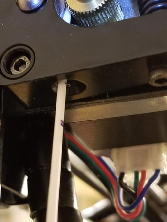 This is how I calibrated the extruder. The marks were at 100 and 110mm. The 100mm mark was just aboout perfect when I sent the G1 E100 command.
Extruder Calibration:
From M503, I pulled the configured steps per mm, the Extruder is 92.6 steps/mm:
Recv: echo: M92 X80.00 Y80.00 Z400.00 E92.60
Due to the printer preventing cold extrusion, the hot end needed to be heated above 170C.
I then sent the printer a G0 E100 command to extrude 100mm, got 96mm - use this guide.
Send: M104 S215
Send: M83
Send: G1 F50
Send: G1 E100
100/96 = 1.0416
1.0416 x 92.6 = 96.45 or 96.5 (new value)
Set it using this, and re-test:
M92 E96.5
Update - went back and re-calibrated it and changed it to E98.97.
PID Autotune (nozzle)
Here I used 215 degrees C and 8 iterations to test with, M106 sets the fan to full:
M106 S255
M303 E0 C8 S215
Result:
Recv: Classic PID
Recv: Kp: 15.66 Ki: 0.92 Kd: 66.70
Recv: #define DEFAULT_Kp 15.66
Recv: #define DEFAULT_Ki 0.92
Recv: #define DEFAULT_Kd 66.70
To set the values:
M301 P15.66 I0.92 D66.70
Note that I am still working on this since the hot end temp is a bit unstable still, I think it needs a sock.
Cura Start Gcode
I added these to the default stuff in the Cura I3 Mega Profile:
G28 ;Home
M420 S1 Z2 ;Enable ABL using saved Mesh and Fade Height
TMC2208 Vref Adjustment
Found that the TMC2208's were set between 1.2 and 1.4 volts for Vref. Set them as follows:
X = 0.9V
Y = 1.2V
Z = 1.2V
E0 = 1.3V
E1 = 1.2V (believe this is the 2nd stepper)
Wrapping it up
Lastly, when I ran a test print to do a flow calculation, I noted that the extrusion was inconsistent (walls were undersized, even with flow set correctly). So I took a look at the nozzle and noticed it was in serious need of replacement. Since I had a couple spares I swapped it out and what a difference it made. I also ordered a silicone sock for the hot end block since despite letting my buddy know this was gratis and I did not want anything, he slipped a $20 in with the parts, well now I have to return the favor by slipping in some parts with his printer :D The sock should help with the temp fluctuations I noticed when doing the PID tuning. They seem to be more pronounced when the nozzle is close to the bed which makes sense, as that is where the part cooling air will most likely hit the block/nozzle. I will re-run PID tuning when the block is "socked".
Lastly, when I ran a test print to do a flow calculation, I noted that the extrusion was inconsistent (walls were undersized, even with flow set correctly). So I took a look at the nozzle and noticed it was in serious need of replacement. Since I had a couple spares I swapped it out and what a difference it made. I also ordered a silicone sock for the hot end block since despite letting my buddy know this was gratis and I did not want anything, he slipped a $20 in with the parts, well now I have to return the favor by slipping in some parts with his printer :D The sock should help with the temp fluctuations I noticed when doing the PID tuning. They seem to be more pronounced when the nozzle is close to the bed which makes sense, as that is where the part cooling air will most likely hit the block/nozzle. I will re-run PID tuning when the block is "socked".

The old nozzle was shooting filament out the side rather than straight down and making a weird mess. It was also causing underextrusion, possibly due to either a partial blockage or burr. Prints were still looking OK, but should be better now. Either way the new nozzle is a clear improvement and easy fix.
Resources
DavidRamiro's Marlin-Ai3M-2.0.x-2.0.x code here
Great guide for using the z-min for the BLTouch in the video here by Ted Marozzi
Dai Hai Zu's video here is a comprehensive guide to installing TMC2208 stepper drivers
This is a great diagram of the board, from Korobok at Thingiverse.com (note that this is for the original board, not 1.1, but all pins but the servos should be the same):
https://cdn.thingiverse.com/assets/32/8c/6d/ab/5b/TriGoRiLLa_PINs.pdf
