Assembly Instructions for the MMM Recirculating Filter
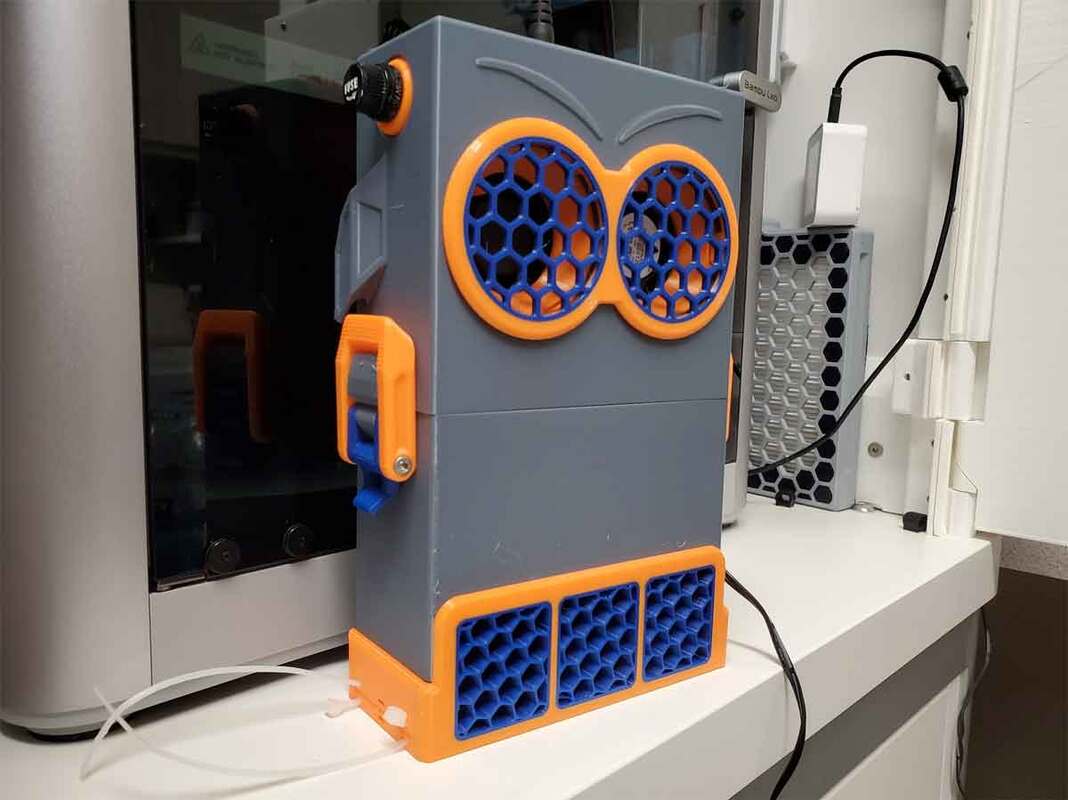
This page shows how I assembled my "Marvin the Microparticle Machine" (MMM) filter, which is a ground up variation on the awesome Bento Box design by Thrutheframe on Printables. This model is a bit more difficult to print, will cost a bit more due to the PWM controlled fans, and may not be for everyone, but that's OK, I made it for me :D The model was designed with the following changes in mind, compared to the original Bento Box:
To start with though, here is the Bill of Materials (BOM):
- Bigger fans, specifically 5020 blowers.
- A bigger HEPA filter.
- Fewer compartments, and no magnets.
- A removable carbon tray.
- Some room for possible additions.
To start with though, here is the Bill of Materials (BOM):
Bill of Materials
These are the parts I used and links to them. The links are provided for reference, but the Amazon links are affiliate links (so I get a small referral bonus if they are used). AliExpress is usually going to be cheaper, but takes about 2-3 weeks for delivery (typically). There may also be other alternatives to these parts, and later remixes may allow using less expensive components (such as cheaper 2 wire fans), however the current version which I am using used these parts:
- Qty 2 - Delta Electronics BFB0512LD 5020 50x50x20mm 12V 0.15A Blower fans (4 wire for PWM control). These are also available at ebay, but make sure to get the 4 wire version.
- Qty 1 - DC12V Manual 4-Wire PWM Fan Speed Motor Controller Board, look for ones with pre-soldered power wires if possible (AliExpress or Amazon)
- Qty 1 - 5.5 x 2.1 DC Power Jack Socket (I used these from Amazon, though other types will work as well)
- Qty 1 - 5x20mm Screw Cap Fuse Holder (See the note in the instructions below on wired vs unwired fuse holders Amazon)
- Qty 1 - 5x20mm fuse - use your best judgement on sizing, but I am going to use a 1A fuse. If you use a fuse, keep in mind that some cheap no name brand assortments of fuses are garbage (name brands like Bussmann and Littlefuse are good, reliable brands). These are common fuses though so they should be available at any hardware store (and you will probably find quality fuses there vs at Amazon).
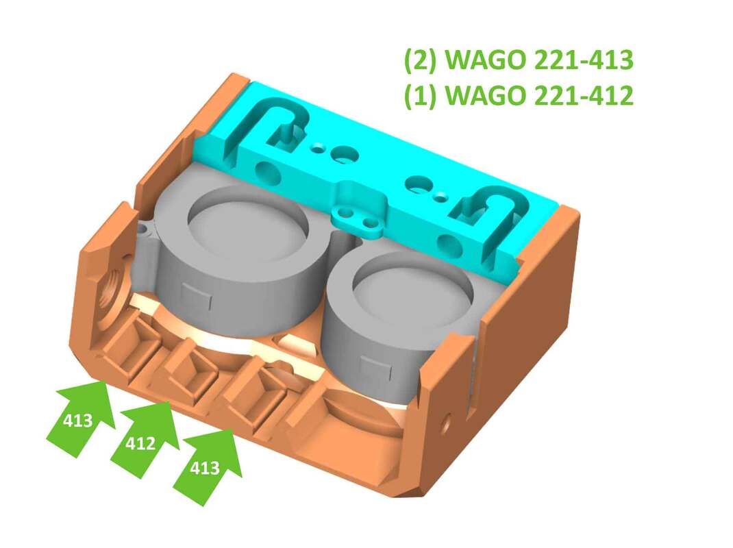
- Qty 2 - WAGO 221-412 (2 port) wire nuts (I used this assortment from Amazon)
- Qty 1 - WAGO 221-413 (3 port) wire nut (I used this assortment from Amazon)
- Qty 1 - 105x37mm HEPA filter for a Kitfort Kt-532 Robot Vacuum (AliExpress or Amazon)
- Qty 1 - 12V DC power supply which can supply at least 500mA (I used a 12v DC 1A supply, a UL listed supply like this should work OK)
- Qty 4 - M3x20mm SHCS (this assortment from Amazon has most of the M3 hardware needed)
- Qty 2 - M3x25mm SHCS
- Qty 6- M3x30 SHCS
- Qty 2 - M3x8mm BHCS or SHCS
- Qty 1 - M3x6mm SCHC (used to mount the base to the floor the X1C printer)
- Qty 2 - M3x20mm FHCS (Amazon)
- Qty 2 - M3 nuts
- Qty 2 - Double sided tape or Large 3M Command Strips (used to mount the base to the floor the X1C printer).
- Qty 1 - Activated Charcoal (Coconut Shell) Carbon. I use this, however whichever is used, make sure to get the type that is NOT acid washed, since that can cause corrosion of steel parts in the printer. The size should also be no larger than the linked 4x8 mesh carbon.
- Qty 1 - Electrical or Kapton tape (AliExpress or Amazon)
- Qty 1 - small zip tie (Amazon)
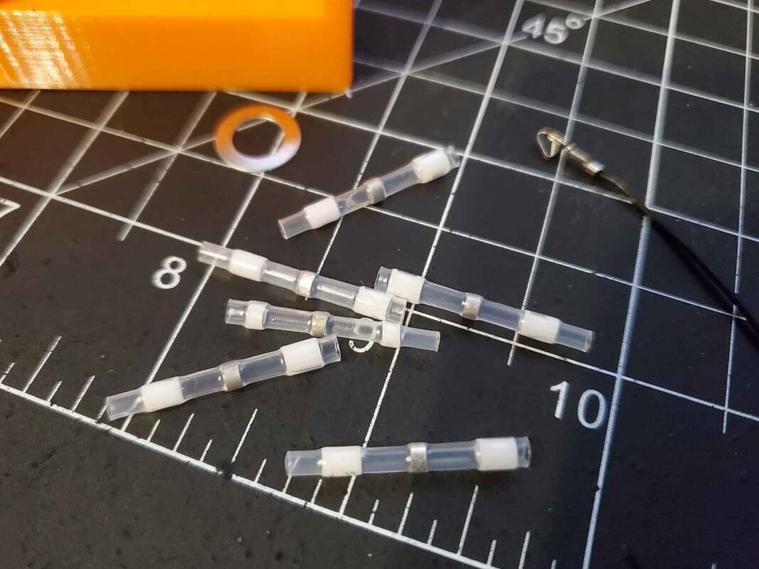
- Optional - Heat Shrinkable Solder Seal Connectors (I used the smallest white connectors, like the ones in this assortment on Amazon)
- Optional - 5mm LEDs set up with a resistor to be used with 12V. I was too lazy to make them so bought these (which are similar to these on Amazon)
Tools Required
This is a list of tools I feel would be needed, however there may be several ways to do things, so it's not a definitive list.
- A hex wrench or driver for the M3 SHCS
- Wire cutters and strippers
- Hot air gun (I used this one). It is hot enough to melt the solder when using the Solder Seal connectors.
- A 3D printer of course, one with an MMS/AMS is preferred due to some multi-color prints.
Step 1 - Print the Parts
You can use the included 3MF profile and skip this section. But if you are going to work with the raw STL's, printing this requires a few extra steps, due to the meshes used on several parts. Additionally, some parts are designed for multicolor printing, though they can be printed using one color (these are the base/cradle, the fan guards and the top cover). I used OrcaSlicer and Bambu Studio, so settings will based on it's settings. I printed all the parts on a Bambu X1C, with an AMS, and used PETG for all the parts.
Most parts can print normally, I used 0.2mm layers, 2 walls and 15% gyroid infill on all parts. There are a few parts however that require some special treatment in the slicer. These are the parts where I used the slicer to create a mesh, and although it sounds tricky, it's pretty simple to do. The parts which require a mesh to be created using the slicer are the following:
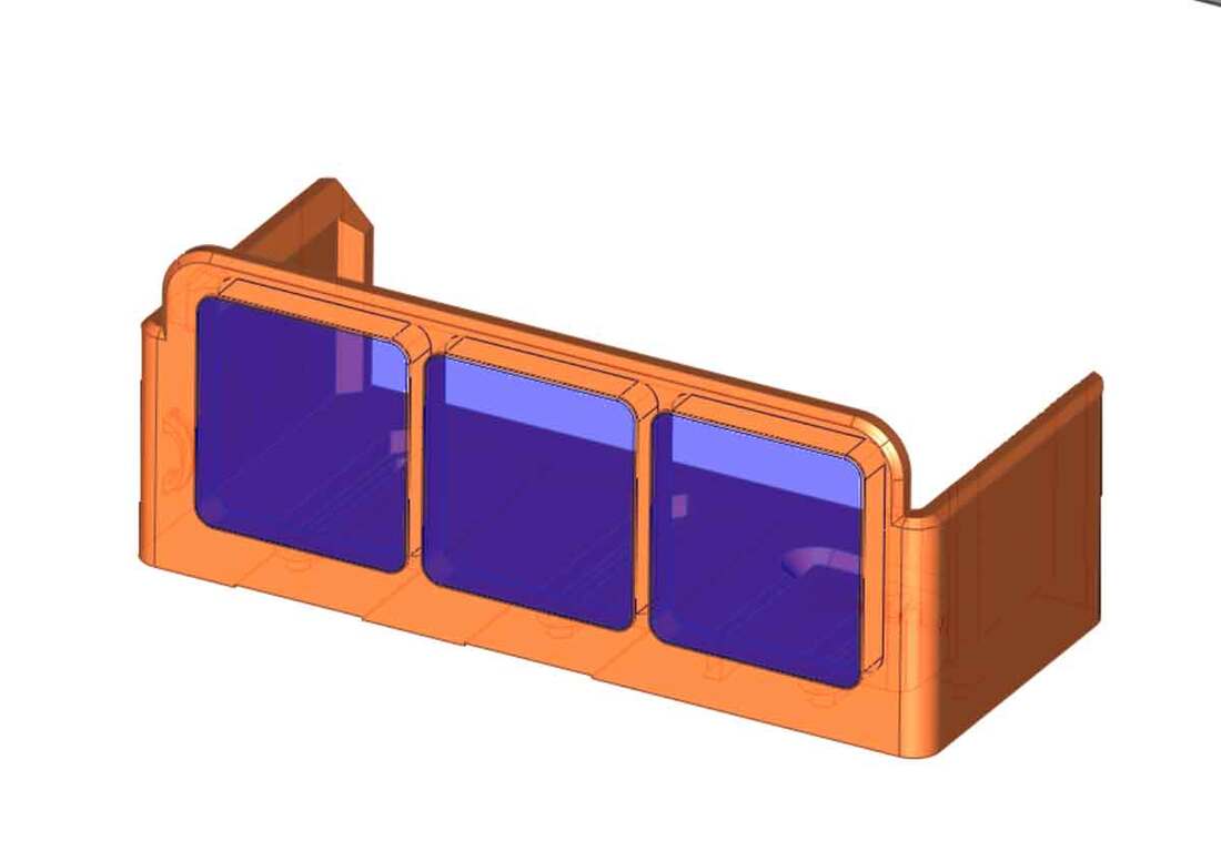
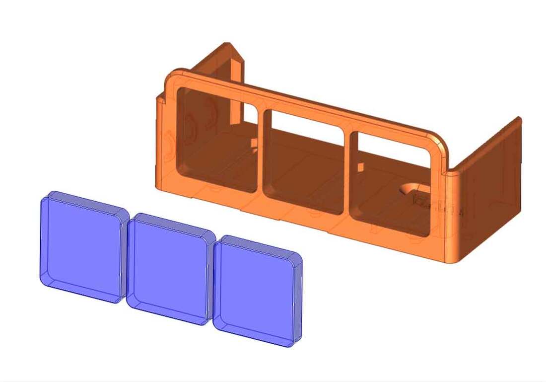
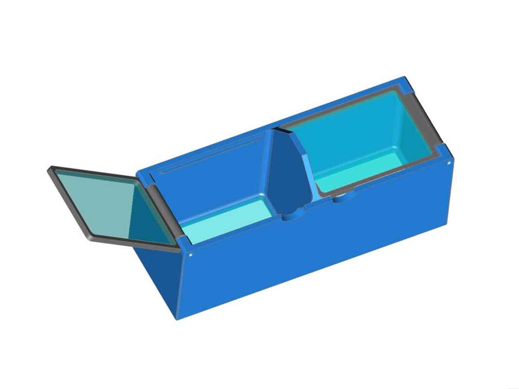
Each of these parts have at least two parts, which should be loaded together into OrcaSlicer or Bambu Studio (or your preferred slicer), and need to retain their relationship, but can be manipulated separately. For example, the base cradle has two parts as shown below:
Most parts can print normally, I used 0.2mm layers, 2 walls and 15% gyroid infill on all parts. There are a few parts however that require some special treatment in the slicer. These are the parts where I used the slicer to create a mesh, and although it sounds tricky, it's pretty simple to do. The parts which require a mesh to be created using the slicer are the following:
- The activated carbon box and lids
- The top cover
- The base cradle
Each of these parts have at least two parts, which should be loaded together into OrcaSlicer or Bambu Studio (or your preferred slicer), and need to retain their relationship, but can be manipulated separately. For example, the base cradle has two parts as shown below:
When loading these into the slicer, add them both at the same time. The files can simply be dragged together onto the buildplate in the "Prepare" tab in OrcaSlicer/BambuStudio. There will be a pop up warning asking if it should "Load these files as as a single object with multiple parts?" which would be answered with "Yes".
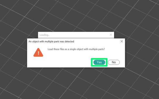
The models will load and will be grouped together, so they can both be moved without losing their positions relative to each other.
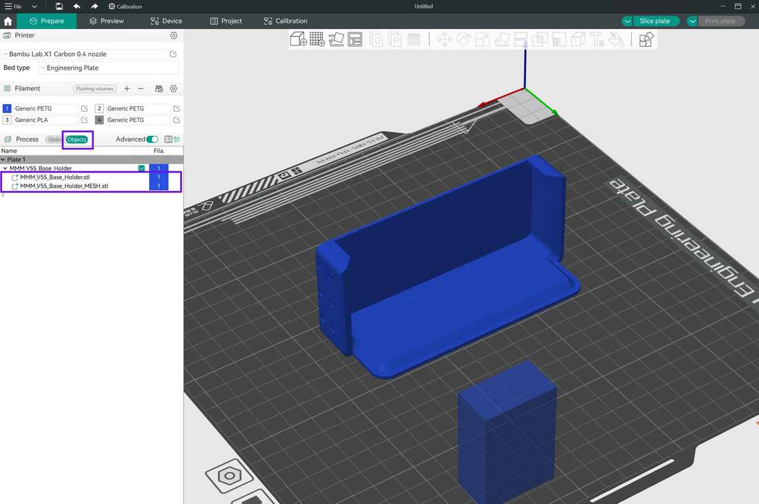
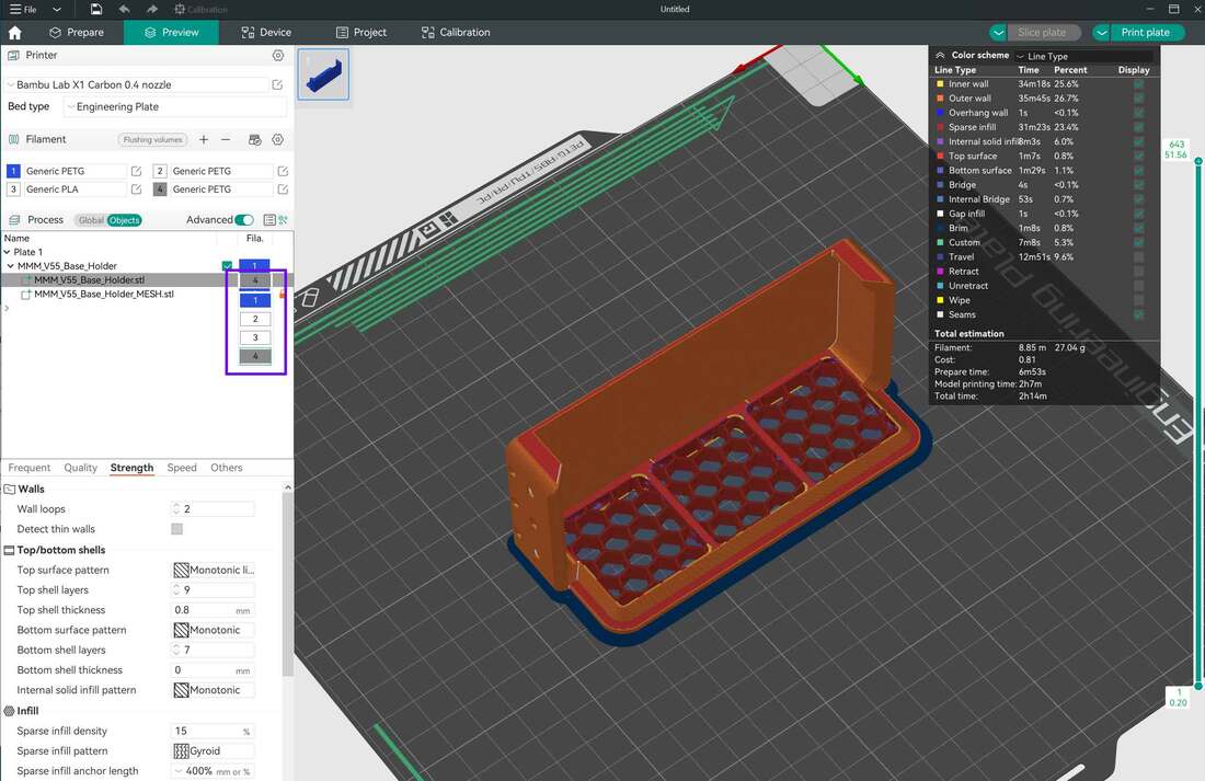
OrcaSlicer and BambuStudio have settings which are defined globally for all objects on the buildplate, and also settings which can be defined for each object on the buildplate. In this case there are two objects on the buildplate, one is the "base_holder" and the other is the "base_holder_mesh". We need the "base_holder" to print normally, however the "base_holder_mesh" needs to print with no top or bottom layers, with 10% Honeycomb infill. The colors for each object can also be set independently if using an AMS.
OrcaSlicer and BambuStudio have settings which are defined globally for all objects on the buildplate, and also settings which can be defined for each object on the buildplate. In this case there are two objects on the buildplate, one is the "base_holder" and the other is the "base_holder_mesh". We need the "base_holder" to print normally, however the "base_holder_mesh" needs to print with no top or bottom layers, with 10% Honeycomb infill. The colors for each object can also be set independently if using an AMS.
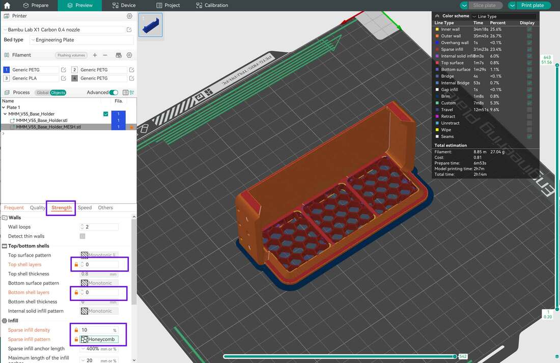
First, to change the settings to create the mesh, the object for the "base_holder_mesh" is selected, and then under the "Strength" tab, I changed the following settings from their defaults:
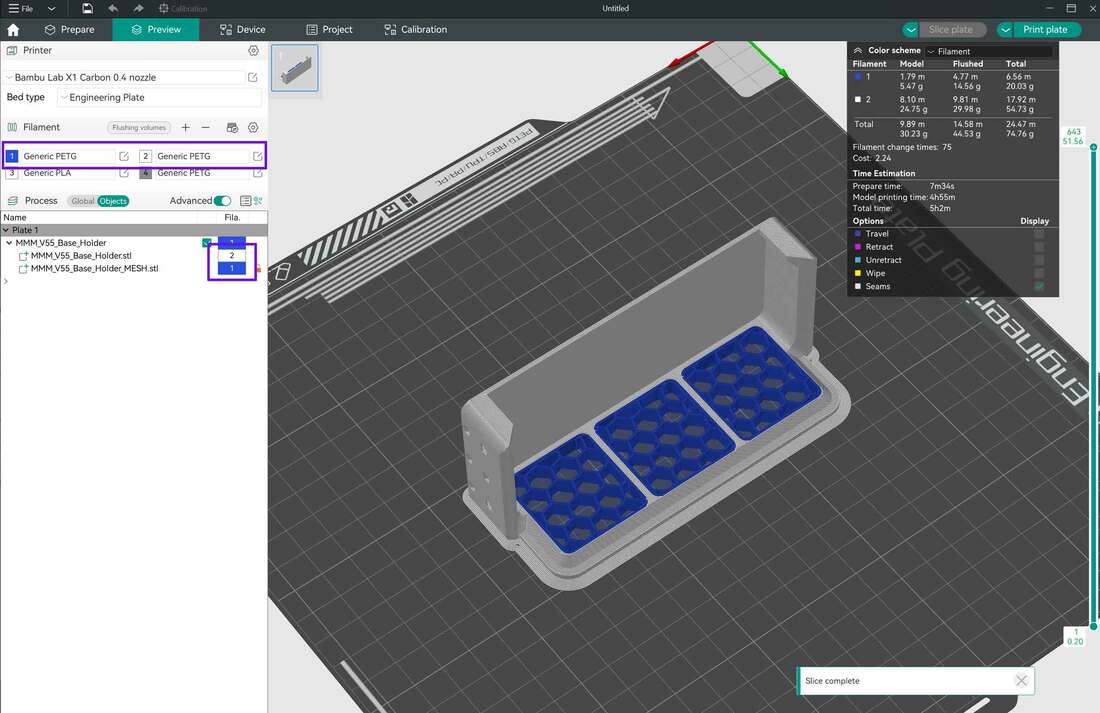
Then click "Slice Plate" in the upper right hand corner to preview the print.
- Top Shell Layers = 0
- Bottom Shell Layers = 0
- Sparse Infill Density = 10%
- Sparse Infill Pattern = Honeycomb (watch out that 3D Honeycomb is not used)
Then click "Slice Plate" in the upper right hand corner to preview the print.
Additionally, if using an AMS, the colors for the mesh and main object can be changed by selecting the object and clicking (or clicking several times) on the "Fila." box which should show the color of the default filament loaded. From here there will be a dropdown box where other colors can be selected.
This same process can be used on the other parts which require meshes to be added using the slicer.
The carbon box meshes are created the same way, however they will use the following settings:
The carbon box meshes are created the same way, however they will use the following settings:
- Top Shell Layers = 0
- Bottom Shell Layers = 0
- Sparse Infill Density = 25%
- Sparse Infill Pattern = Honeycomb (watch out that 3D Honeycomb is not used)
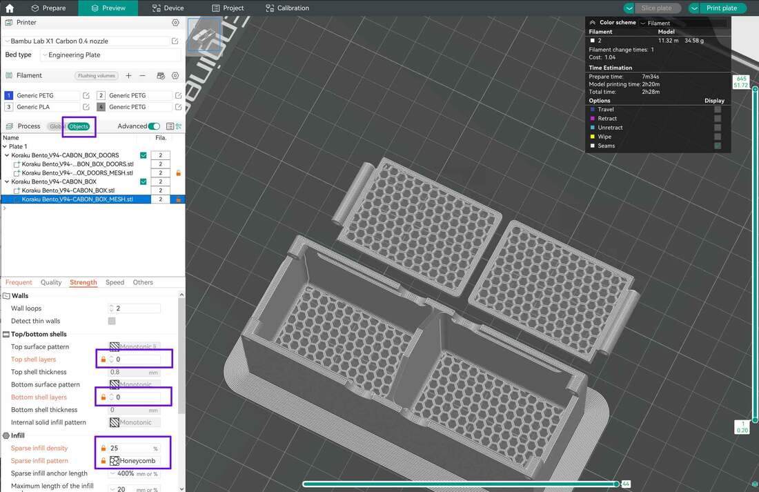
That's all there is to making the meshes using the slicer.
If you are wondering where the settings are for the brim and supports (which are not required for these parts), they are under both the "Global" process settings as well as the "Object" process settings, and can be found under the "Support" and "Others" tabs. The default is to have supports off and the brim is set to auto. You can also set the infill (I use Gyroid) under the "Strength" settings. If you make a change under the object process settings, those settings will take precedence over any similar setting in the "Global" process settings. Global process settings are going to be the defaults for any objects which do not have specific settings.
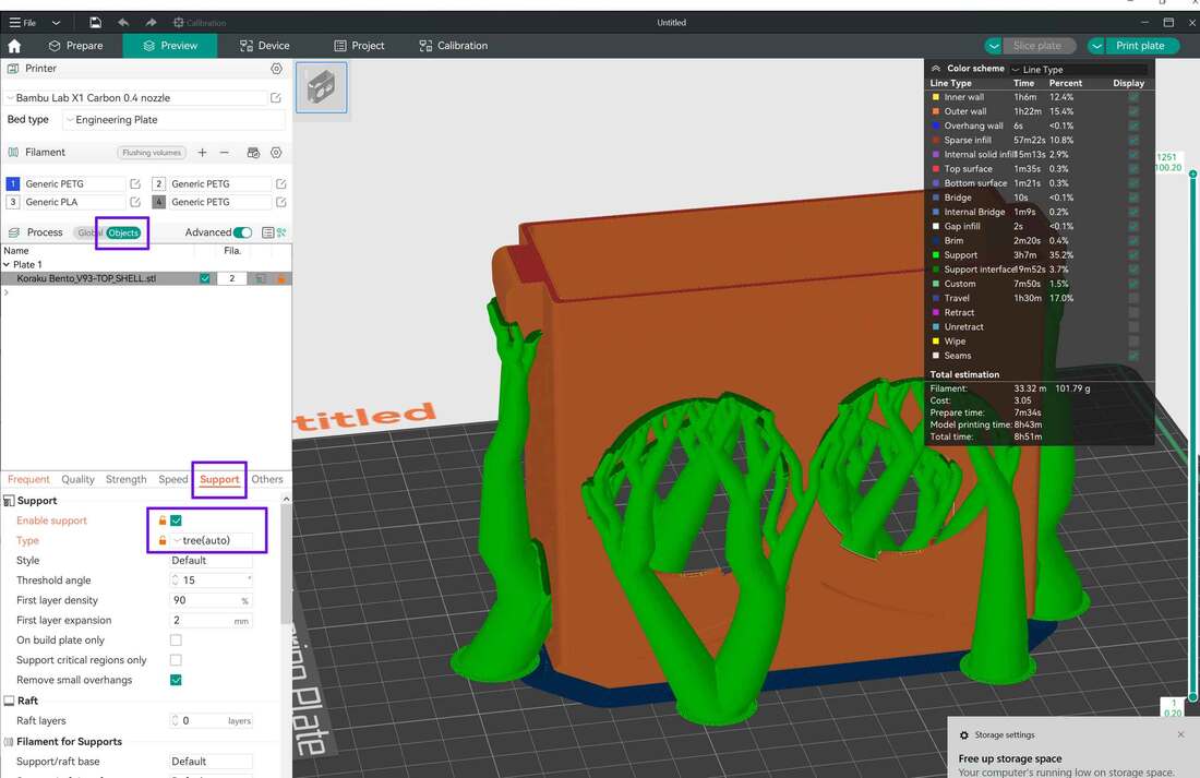
The only other part that needs some special attention is the "top_shell" which is the top part of the filter. It will require supports. Automatic Tree supports *can be used. The support settings are under either the "Global" or "Object" process (I used the Object process), then click the "Support" tab and select the checkbox to "Enable Support" and then use "Type" = "Tree (auto)". When it's done, check over the model to make sure the supports look OK.
If you are wondering where the settings are for the brim and supports (which are not required for these parts), they are under both the "Global" process settings as well as the "Object" process settings, and can be found under the "Support" and "Others" tabs. The default is to have supports off and the brim is set to auto. You can also set the infill (I use Gyroid) under the "Strength" settings. If you make a change under the object process settings, those settings will take precedence over any similar setting in the "Global" process settings. Global process settings are going to be the defaults for any objects which do not have specific settings.
The only other part that needs some special attention is the "top_shell" which is the top part of the filter. It will require supports. Automatic Tree supports *can be used. The support settings are under either the "Global" or "Object" process (I used the Object process), then click the "Support" tab and select the checkbox to "Enable Support" and then use "Type" = "Tree (auto)". When it's done, check over the model to make sure the supports look OK.
The remaining parts have no special requirements, aside from orientation. You can use the auto-arrange or "auto orient" buttons to help with that.
Assembly - Step 1 Build the Base and Carbon Box
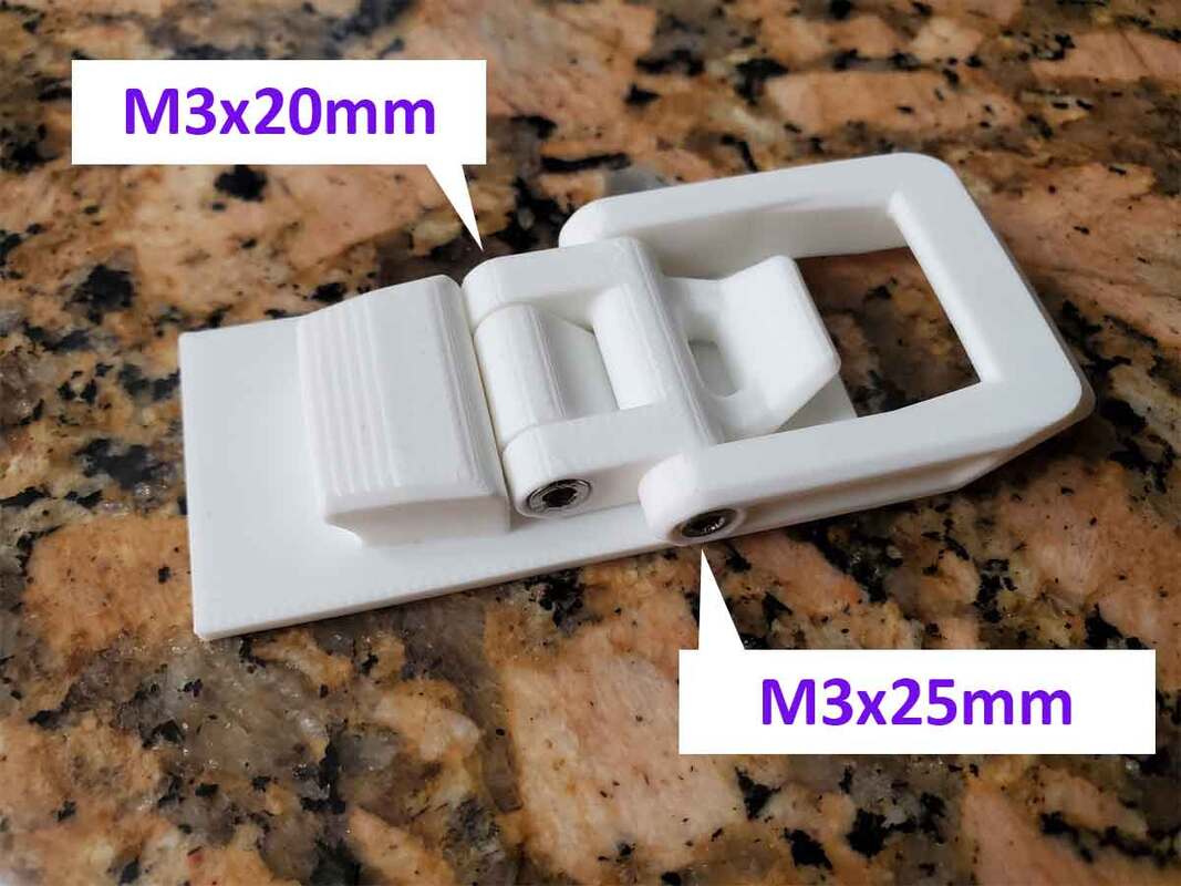
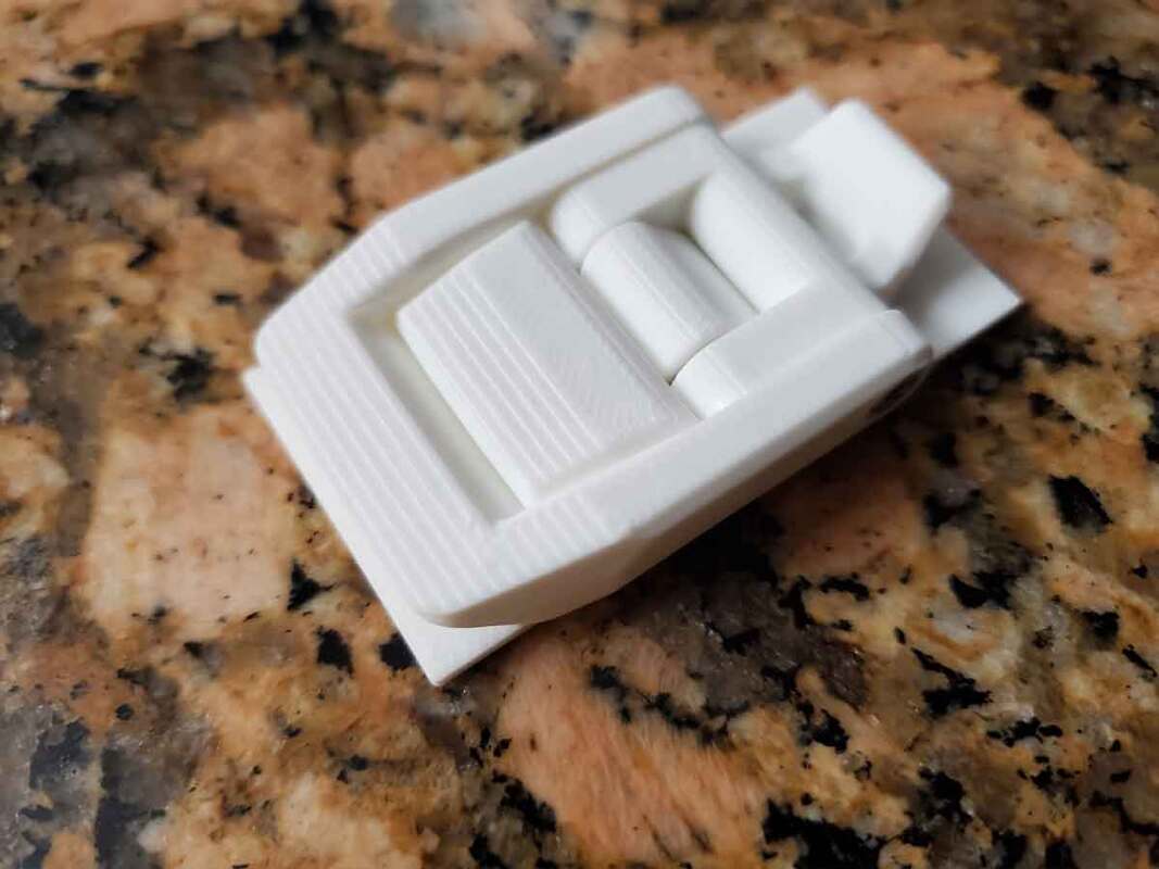
To assemble the latches on the base, two M3x20mm and two M3x25mm socket head cap screws (SHCS) are required. The parts are assembled as shown below.

To assemble the carbon box, a short length of PETG filament is required. These need to be straightened out first, and will be used as hinge pins for the lids. They just slide in from the sides, and that's it. Note that the original design pictured used paperclip wires for the hinges, but the final design uses filament hinge pins.

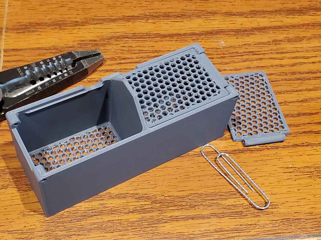
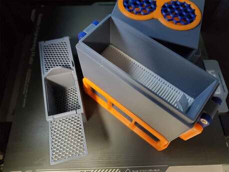
Finally, the HEPA filter can go in the base, followed by the carbon box. The carbon box is of course filled with activated carbon, however I waited till everything was completed before adding the carbon. The carbon should not be overfilled, I filled it about halfway with the 4x8 mesh carbon I used, but if pellets are used, it can be filled more.
Assembly - Step 2 Build the Top
The top is where all the action is, so this step will also be the longest. Be sure to have all the electronic parts on hand before starting. Although it's tempting to snap the fan grill in before assembly, please hold off, that part goes on last.
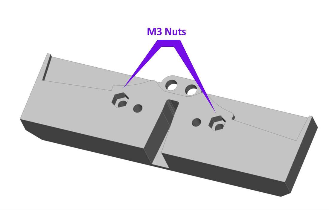
To start, I installed two M3 nuts into the "top_fan_insert_retainer":
To start, I installed two M3 nuts into the "top_fan_insert_retainer":
Optionally, at this step, a pair of 5mm 12V LEDs can be installed. These will use a printed LED holder which is included in the files.
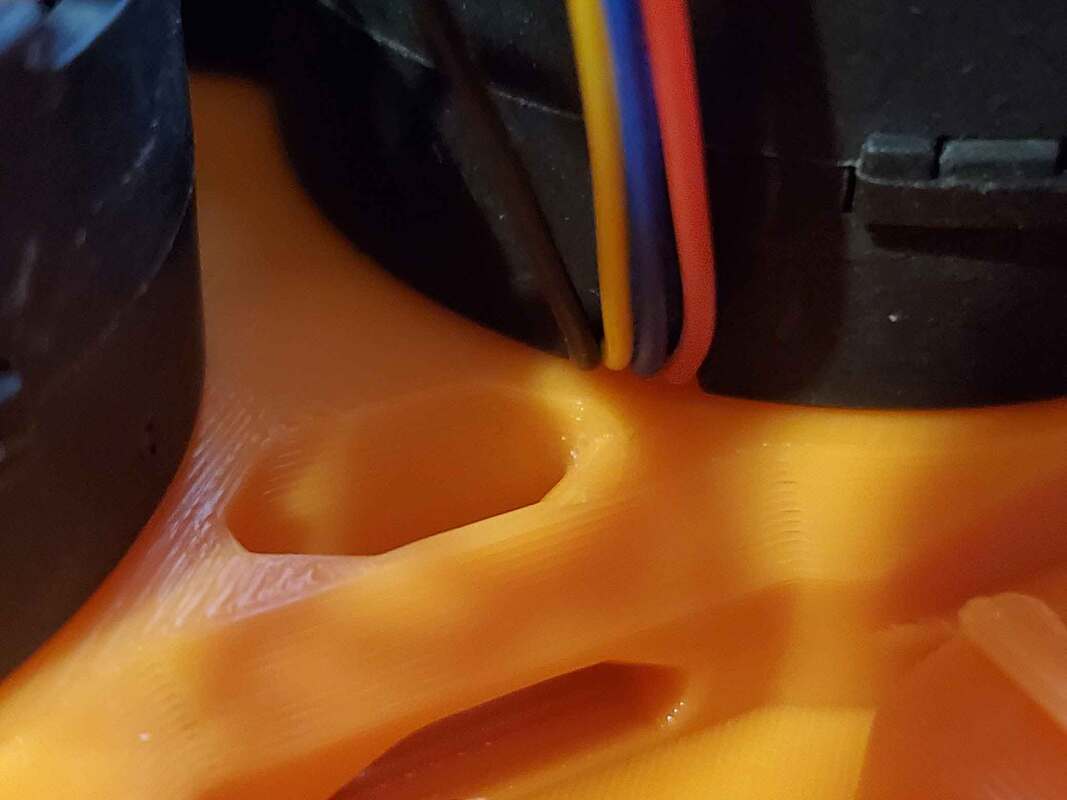
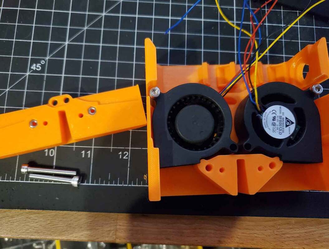
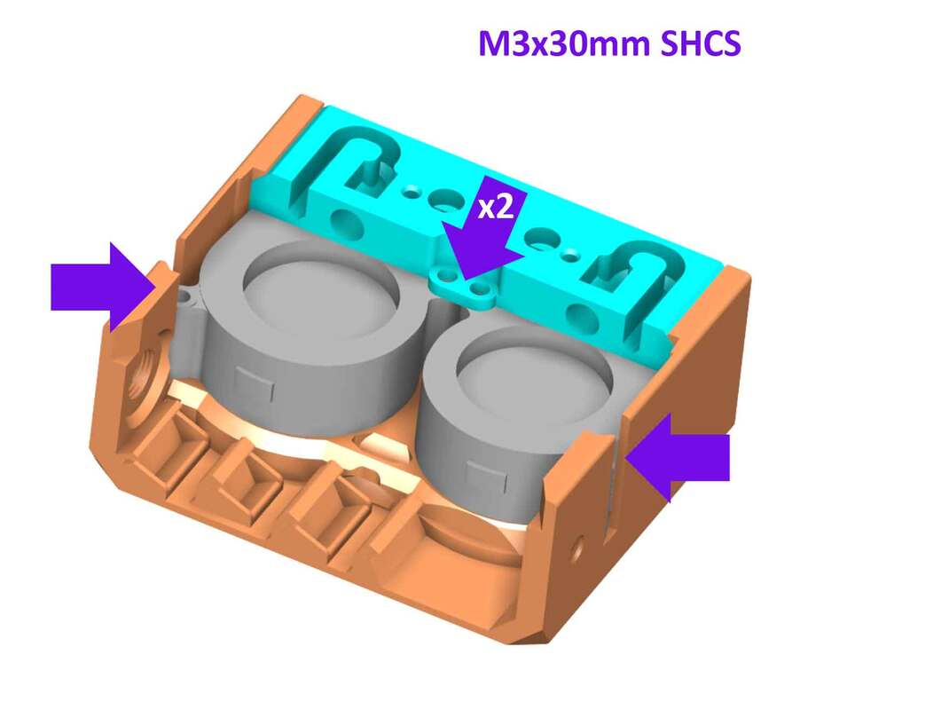
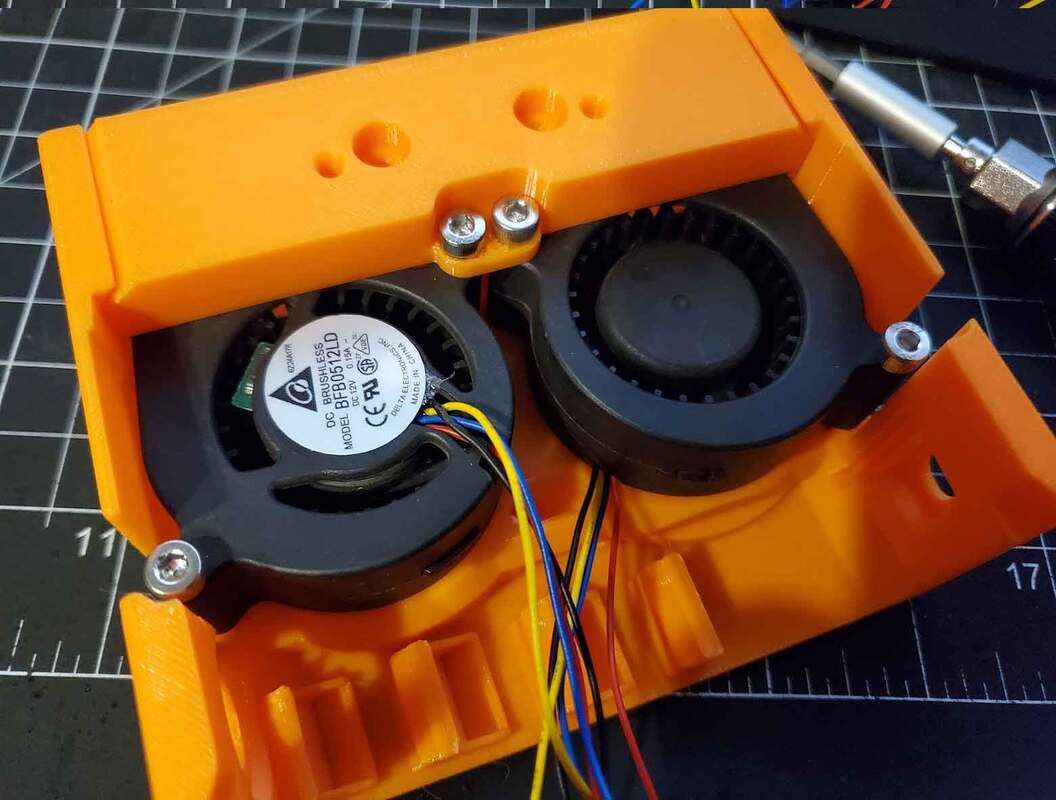
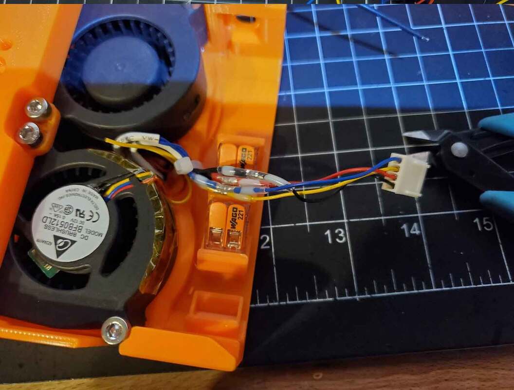
Next the fans can be installed into the "top_fan_insert", this requires four M3x30mm socket head cap screws (although M3x25mm SHCS can work in a pinch). The above "top_fan_insert_retainer" is used as well here. When installing the fans, it's important to make sure that the wires do not get pinched. The fan with the wires facing down, needs to have the wires set in the wire retainer clip on the fan, so that the wires are not pinched (see the pics below). I also used some kapton tape to secure the wires so they would not become loose (and possibly interfere with the spinning of the fan blades).
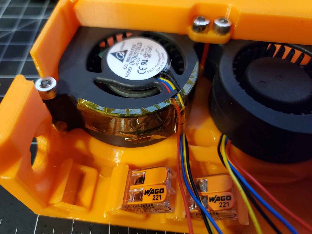
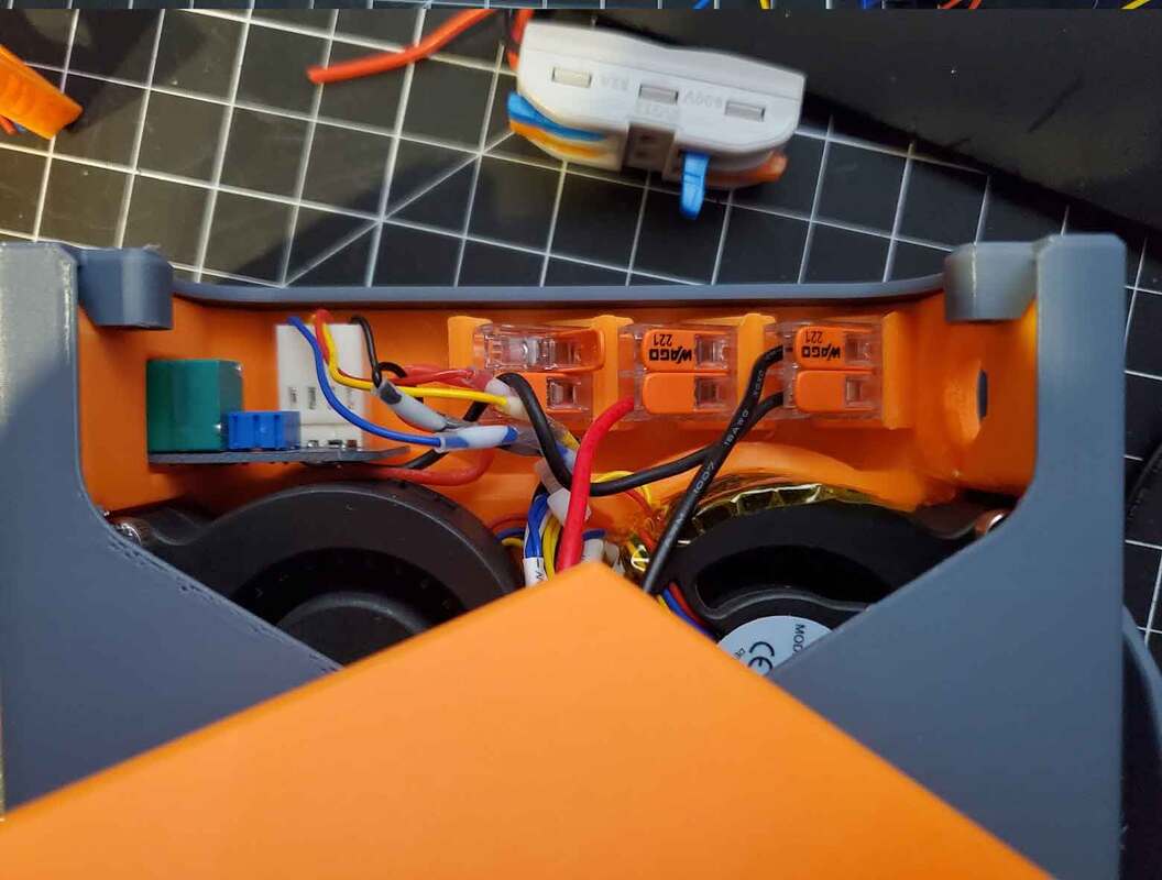
Next the WAGO connectors were installed. There are two 3 port and one 2 port WAGO blocks, and they install according to the picture below. These snap in place.
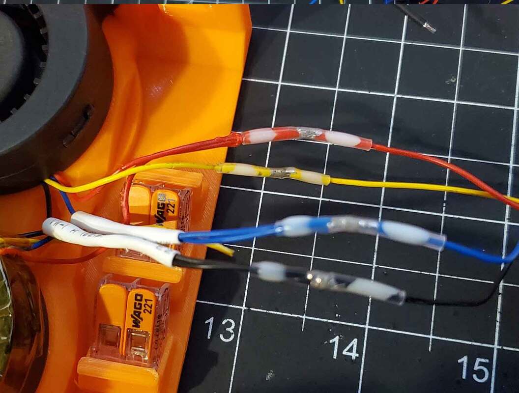
I then connected the wires together from the fans. The fans are wired in parallel, so each color line from each fan was joined using (white) solder seal connectors. I joined them to one of the plug ends cut from one of the fans. The wires need to be kept as short as possible, the excess was tucked between the fans and secured with a zip tie and some tape. There is a hole which can be used as a tie point for a zip tie, located between the fans. Once the fans are installed, the top shell can be slid over the insert.
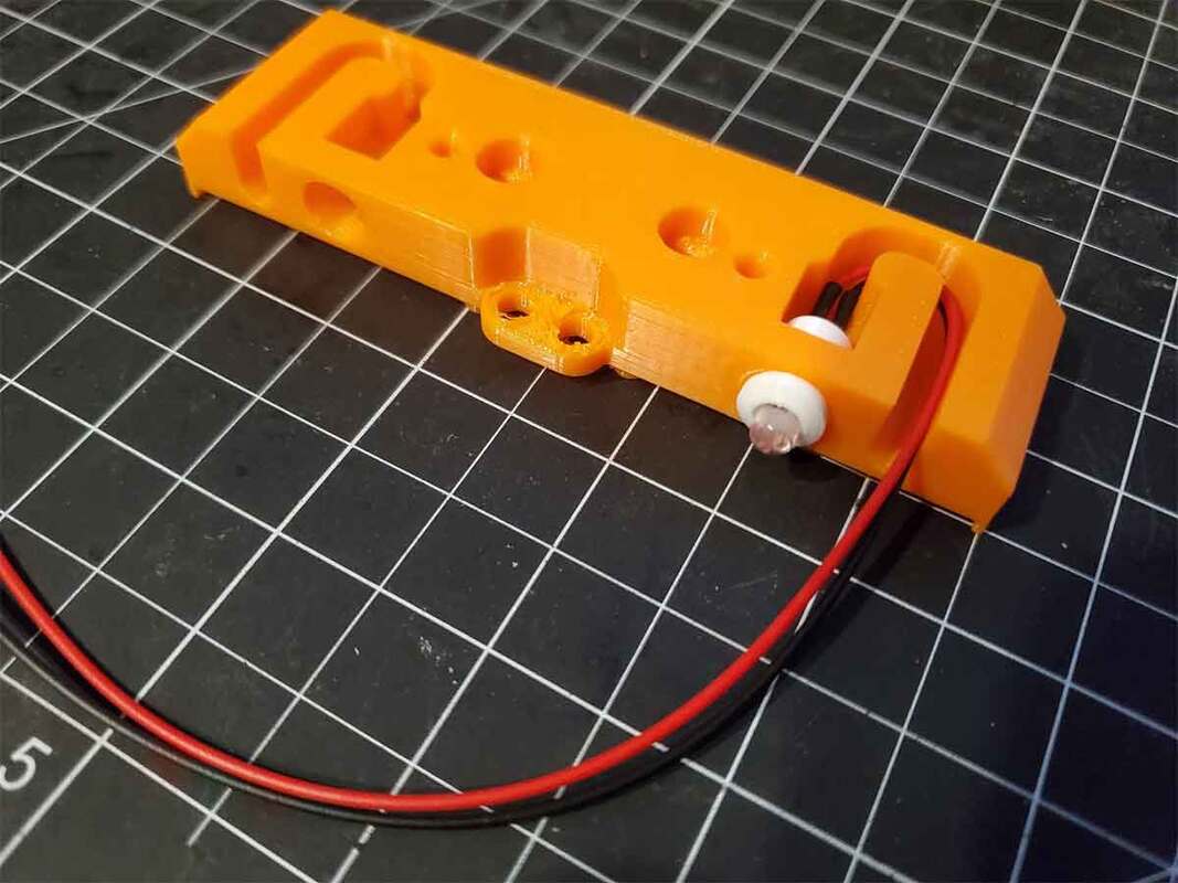
To hold the top shell, two M3x20mm flat head cap screws (FHCS) are used. Button head screws can also be used, and if clearance to the back of the filter is not an issue, cap head screws could be used as well (though I do not recommend using SHCS screws if installing the fan in a Bambu X1C or P1S printer). These M3x20 screws will go into the M3 nuts, previously installed in the "top_fan_insert_retainer".
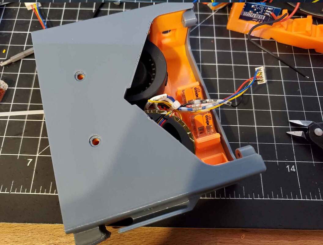
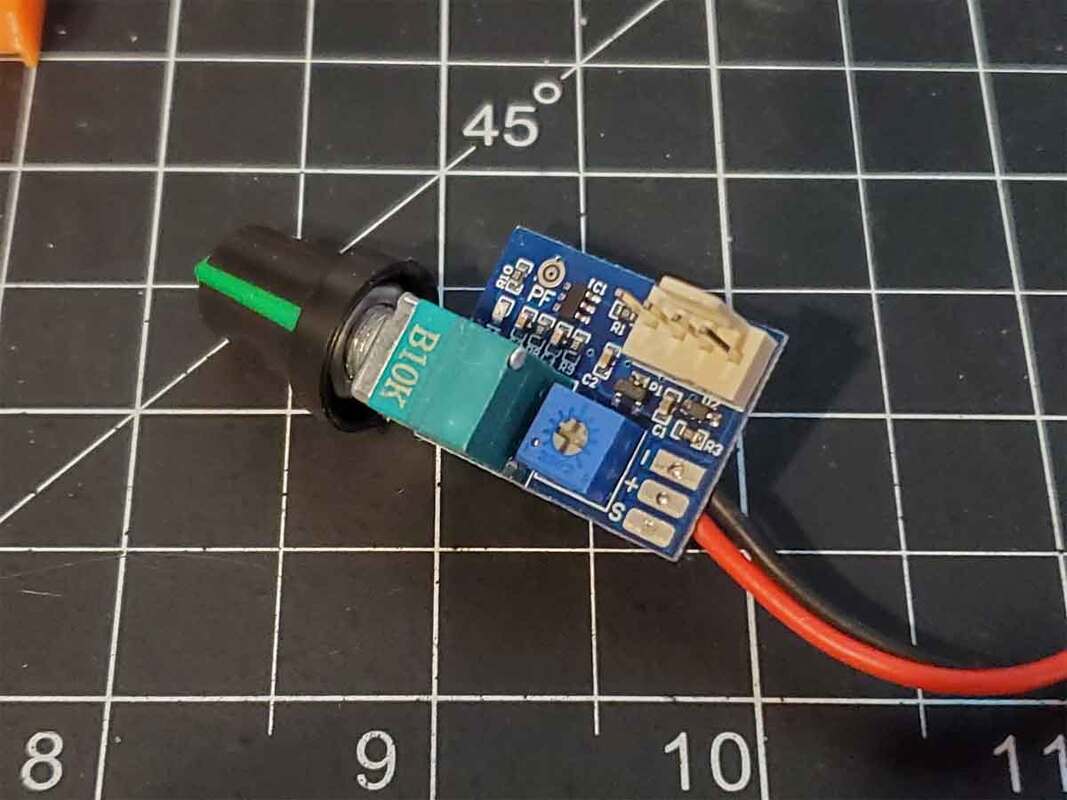
Next the PWM controller was installed. The controller I purchased had pre-soldered wires which was handy since it meant there was zero soldering I had to do. The controller installs by removing the knob and the nut on the controller first. Then it is placed into the pocket in the side of the model and the nut is placed back to secure it. The knob was then installed. The images show a slightly different setup for the WAGO's, than in the final design.
Here is the schematic for the connections. In the prototype I built, I did not plan to use the LED's, but I later updated the model to use them. The drawback of using the LED's is that they will be on all the time, unless power is shut to the filter. That is because the switch on the PWM controller only switches the fans off. It may be possible to connect the fans to the DC power to the fans, which is probably switched off with the fans, however I have not tried that. The LEDs are in any case optional. The fuse is used to protect the positive DC input line, before that is distributed using the 3 port WAGO on the left. This schematic is not tested, though it looks correct to me (feedback is welcome to improve this).
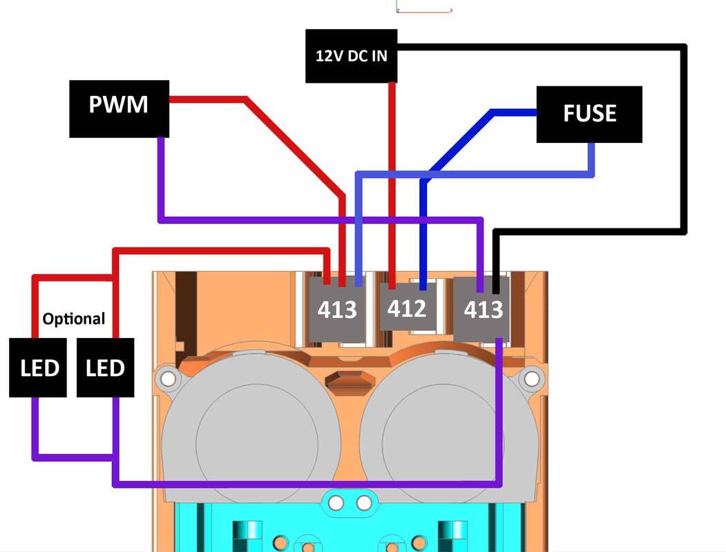
The DC input and fuse were installed, and connected as shown above. The fuse has a printed washer which needs to be installed prior to screwing it into the side of the model. The nut for the fuse will need to be removed prior to installing it, which was difficult on my pre-wired fuseholder. With some effort I was able to remove it. The downside of the pre-wired fuseholder is that the wires may be so thick they prevent easily removing the nut, which is why it may be better to get the unwired fuse holder and solder wires to it.
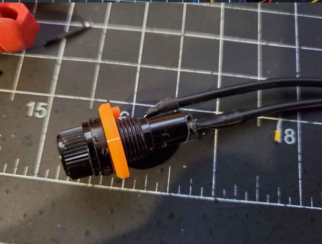
The DC input jack was pre-wired and was installed as shown.
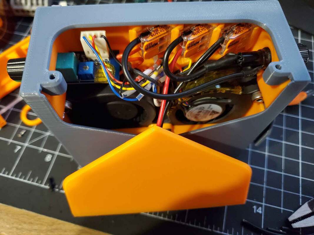
The LEDs are again optional, but they would be connected as well before completing the connections (the LEDs are not shown in the pics due to the prototype being pictured). Before closing up the top cover, verify that no wires are in danger of going into the fans. If necessary, shorten the wires and use tape or zip ties to tidy things up.
Before closing it up, it's a good idea to go over the wiring carefully again and verify things are connected correctly. After I was sure it was all good, I connected the power using a 12v DC power supply and tested things out. When power is connected, the LEDs should come on (if they were used). If the LEDs do not come on, double check the wiring again and make sure polarity is correct for everything. If a multimeter is available, it can be set for DC voltage, and the pads on the PWM controller can be checked for the correct polarity. It's a good idea to not turn on the PWM controller's power to the fans, until it is certain things are correctly connected, since they could be damaged if incorrectly connected.
The DC input jack was pre-wired and was installed as shown.
The LEDs are again optional, but they would be connected as well before completing the connections (the LEDs are not shown in the pics due to the prototype being pictured). Before closing up the top cover, verify that no wires are in danger of going into the fans. If necessary, shorten the wires and use tape or zip ties to tidy things up.
Before closing it up, it's a good idea to go over the wiring carefully again and verify things are connected correctly. After I was sure it was all good, I connected the power using a 12v DC power supply and tested things out. When power is connected, the LEDs should come on (if they were used). If the LEDs do not come on, double check the wiring again and make sure polarity is correct for everything. If a multimeter is available, it can be set for DC voltage, and the pads on the PWM controller can be checked for the correct polarity. It's a good idea to not turn on the PWM controller's power to the fans, until it is certain things are correctly connected, since they could be damaged if incorrectly connected.
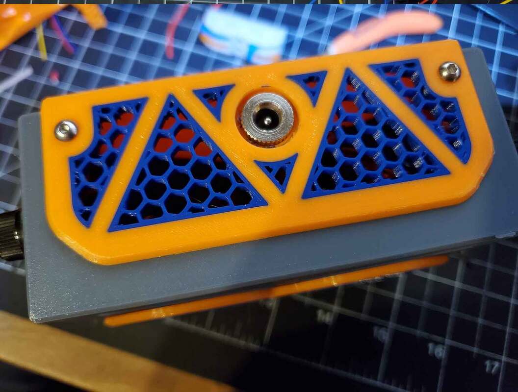
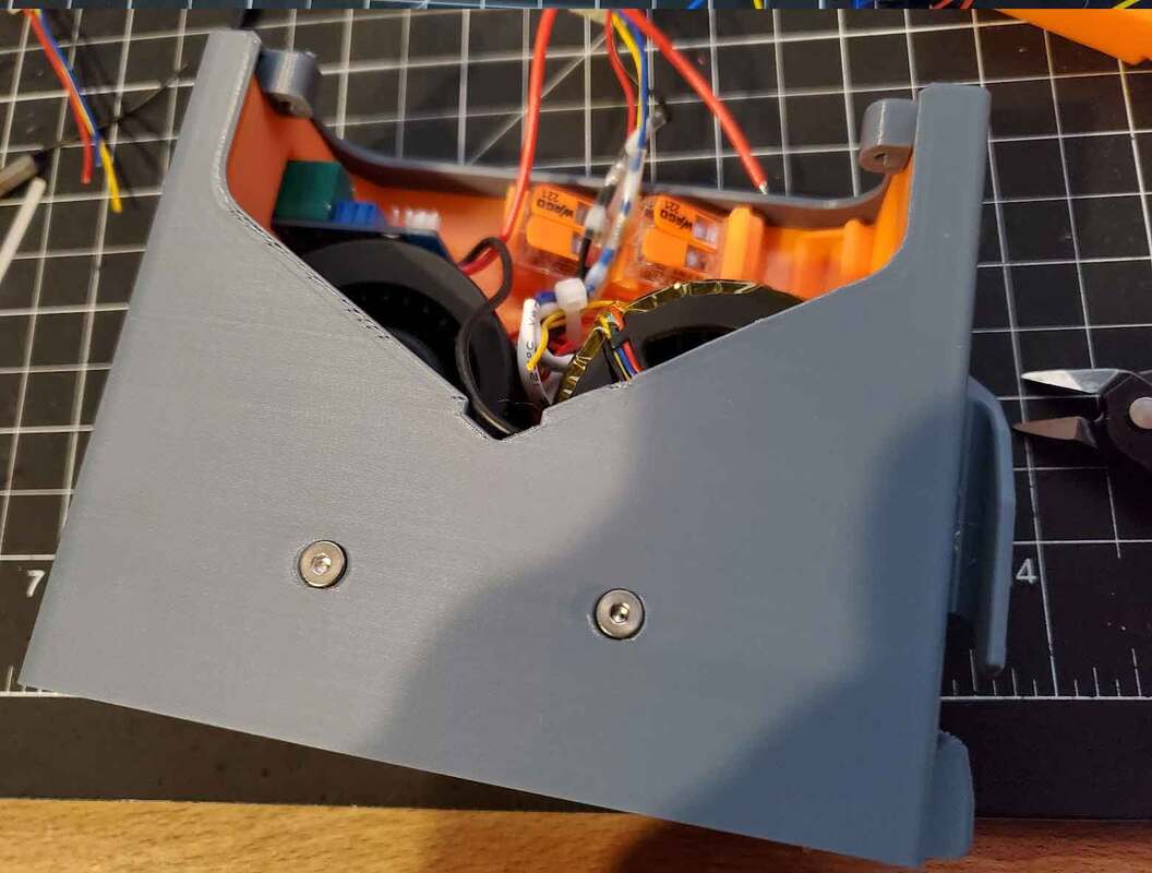
Once everything was tested and working, the top cover, which holds the DC input jack was screwed down, using some M3x8mm BHCS screws.
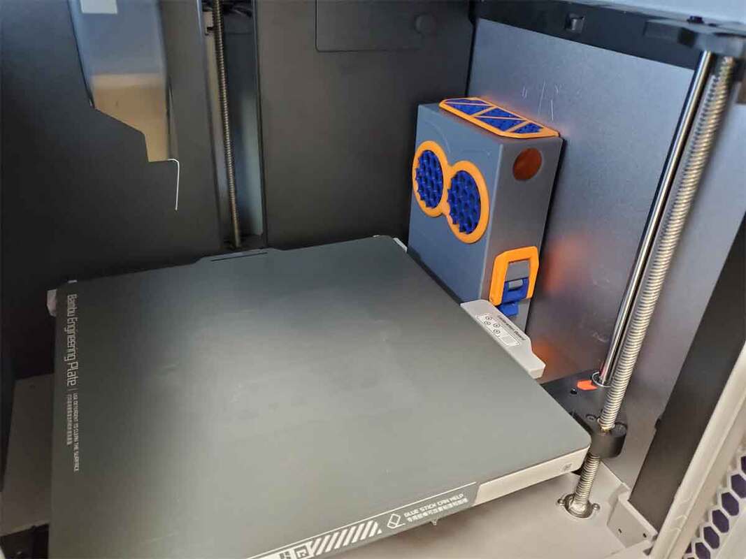
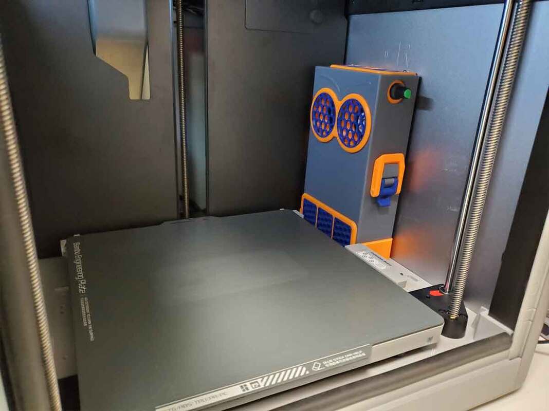
The filter is now mostly completed, aside from installing the cradle in the printer. I waited until it was done to fill the carbon box up (about half way) with the 4x8 mesh activated carbon, and then assembled the top and bottom sections using the draw latches.
The filter is now mostly completed, aside from installing the cradle in the printer. I waited until it was done to fill the carbon box up (about half way) with the 4x8 mesh activated carbon, and then assembled the top and bottom sections using the draw latches.
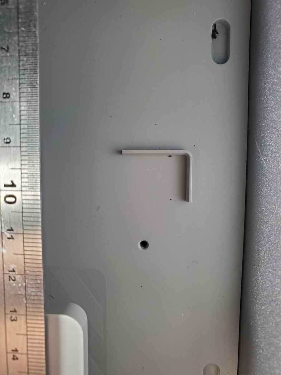
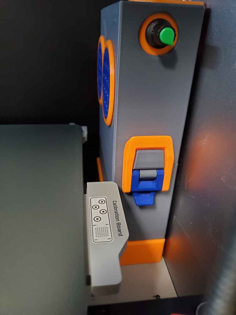
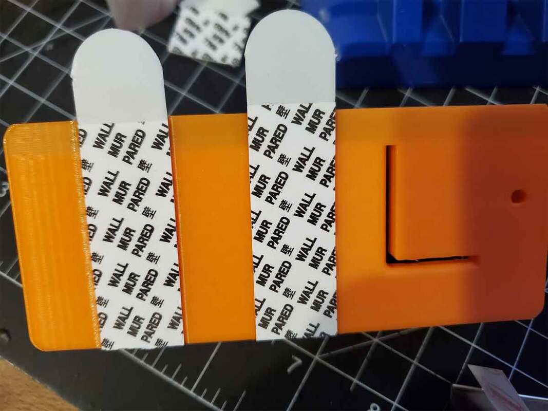
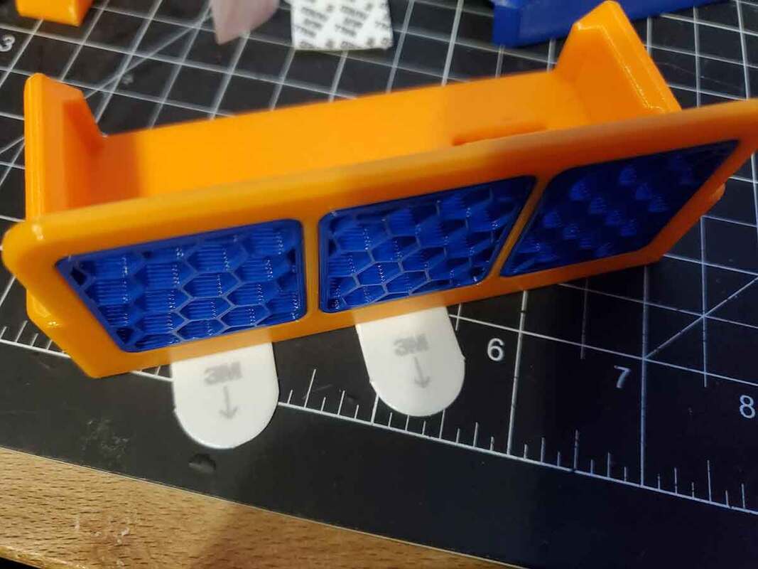
The cradle installs with one M3x6mm SHCS and I also used two large 3M command strips (cut down) to help secure the base/cradle. The M3x6mm screw goes into the hole shown in the 2nd pic. There is an L shaped cutout in the cradle, which helps locating it (at least on the X1C). There are some zip tie holes on the side of the cradle which can be used, but I found it was too difficult to use them in the cramped X1 enclosure so I did not. The version shown in the pictures is the prototype, and since it was made, I found that I could push the filter a bit further to the back of the printer, which will give just a bit more clearance. The wire routing goes from a hole on the base of the printer's left side (towards the back wall), then across the floor along the wall to the right side where the filter is located. It then runs up the side of the filter (where it is retained by the U shaped feature on the side of the filter), and then to the top where it plugs in.