Bambu Spares Storage Box Build Guide

This is a build guide for my Bambu Labs Spares Storage case, which can be found at the links below:
https://makerworld.com/en/models/62636
https://www.printables.com/model/626897-bambu-labs-x1c-spare-parts-case-box-for-stuff
This case is pretty simple to build, but it does require a bit of M3 hardware including the following (quantities are in "(_)"):
(8) M3 x 6mm BHCS
(7) M3 x 10mm SHCS
(2) M3 x 14mm SHCS
(8) M3 x 20mm SHCS
(4) M3 x 25mm SHCS
(2) M3 x 30mm SHCS
BHCS = Button Head Cap Screws
SHCS = Socket Head Cap Screws
This assortment of M3 SHCS has most of the required screws (and you could use the M3x6 SHCS in place of the BHCS, but if you have the BHCS around, they would be a better choice). These M3x6 BHCS will work, but I usually buy assortments (like this one), since metric screws (and M3 in particular) always come in handy for 3D printer repairs and projects.
Note that some of the pics here will look different than the final version. That's because, I'm perfectly happy to use my prototype design, which has about 95% of the features of the final version, and has the same functionality. When I make an minor improvement I don't reprint the entire project unless its necessary (but I will test the component that is changed). Doing things this way saves on filament (and also does not add more junk to a landfill). The downside is that my version is usually a bit less than the final version. But don't worry, you are getting latest and greatest version, with all the improvements (despite what you see in the pics here).
Printing Suggestions
Since some of the parts require a bit of flexibility, I recommend printing in PETG over a more brittle material such as PLA.
Parts on this model will have a close fit, so it's a good idea to calibrate flow or let the X1C do it for you. I used the automatic flow calibration on several PETG materials used in this project, and did not have any issues with assembly (but as always YMMV).
The parts are designed to be printed without supports, but they are not oriented for printing (so some will need to be rotated in the slicer). You can use the included .3mf files with Orcaslicer, which will save a lot of time (since that will take care of part orientation and other settings).
However, if you cannot use the .3mf files, and therefore need to set the files up manually, the tips below may be helpful. They are based on Orcaslicer as well.
The following parts will need to be printed in multiples (quantities are in “( )”):
(2) Bambu_ToolKit-7D_TOP_CLEAT.stl
(5) Bambu_ToolKit-8Q_CUTTER_TAB_x5.stl
The print settings I used are the OrcaSlicer defaults, with the following changes:
Strength > Infill > Sparse Infill Pattern > Gyroid
Quality > Wall Generator > Wall Generator > Arachne
Support > Type > Tree (manual)
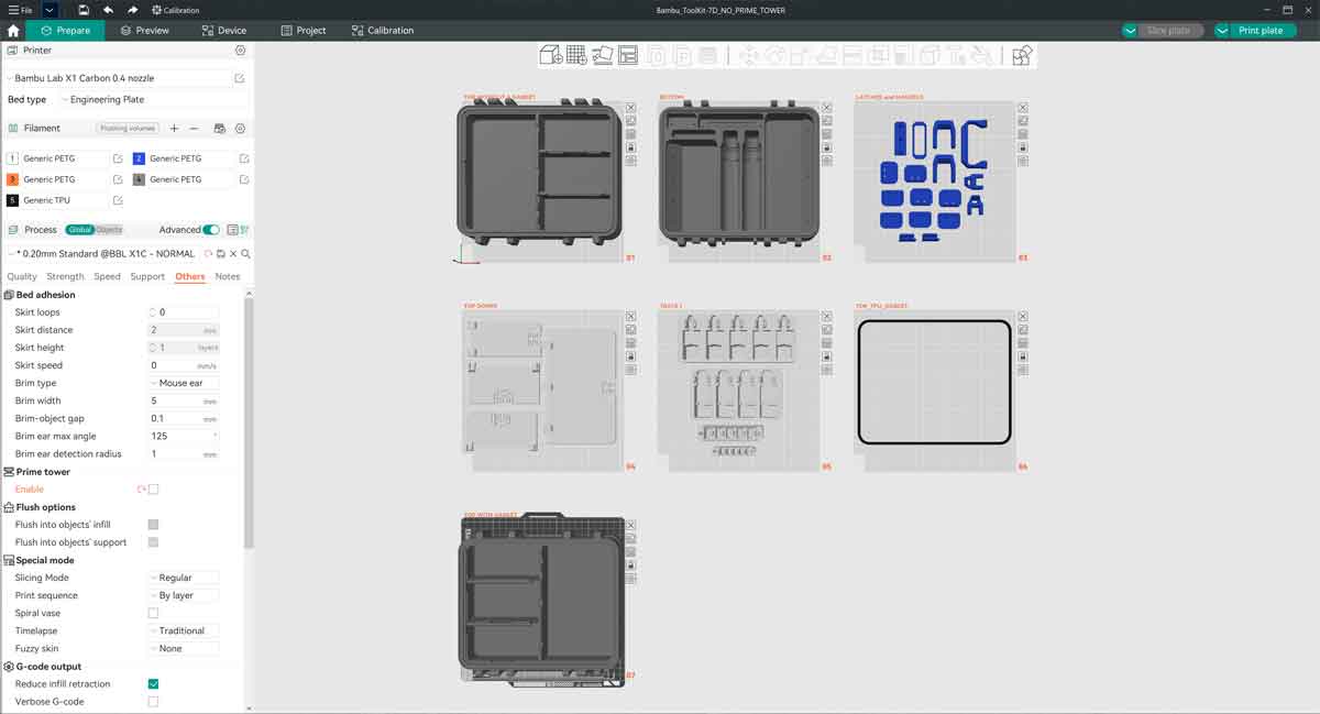
For the TOP and BOT(tom) parts, I also recommend disabling the prime tower. It will waste a bit more material, but since these parts take up most of the build area, there is no room for the prime tower. The AMS is only required on the first several layers of these parts anyway.
Under Process “Global” > Others > Prime Tower > Enable (uncheck)
For the labels and inserts, which use the AMS, the prime tower can be used without an issue.
The top and bottom of the case have an inlay and are therefore designed to be printed in two colors. If there is no AMS, the top and bottom with their inlays can be printed in the same color, which may leave a very fine outline of the text. The top and bottom parts include the following:
TOP (2 colors):
Bambu_ToolKit-9A_TOP_w_GASKET.stl
Bambu_ToolKit-9A_TOP_INLAY_w_Gasket.stl
or
Bambu_ToolKit-9A_TOP_NO_Gasket.stl
Bambu_ToolKit-9A_TOP_NO_Gasket_INLAY.stl
BOTTOM (2 colors):
Bambu_ToolKit-9A_BOT.stl
Bambu_ToolKit-9A_BOT_INLAY.stl
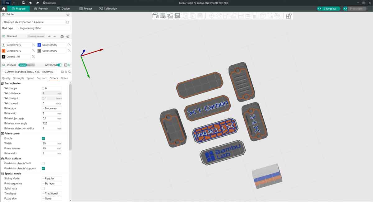
The parts with "TOP_LABEL", "BOT_5X_SD" and "BOT_2X_SD" are designed for multicolor printing using the AMS.
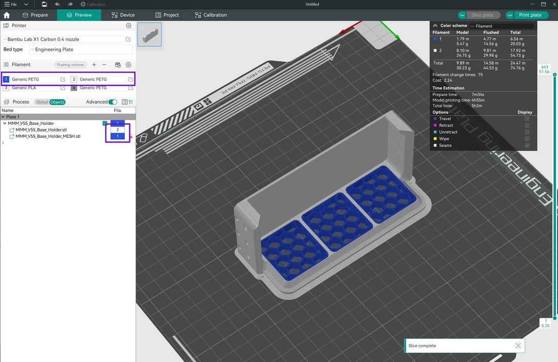
When loading multicolor parts into OrcaSlicer, I select all the parts which are related, and drop them onto the build plate together. For example, I would load "Bambu_ToolKit-9A_TOP_NO_Gasket.stl" and "Bambu_ToolKit-9A_TOP_NO_Gasket_INLAY.stl", together at the same time, into OrcaSlicer. This way, the files will maintain their relationship to each other. The files can simply be dragged together onto the build plate in the "Prepare" tab in OrcaSlicer. There will be a pop up warning asking if it should "Load these files as as a single object with multiple parts?" which would be answered with "Yes".
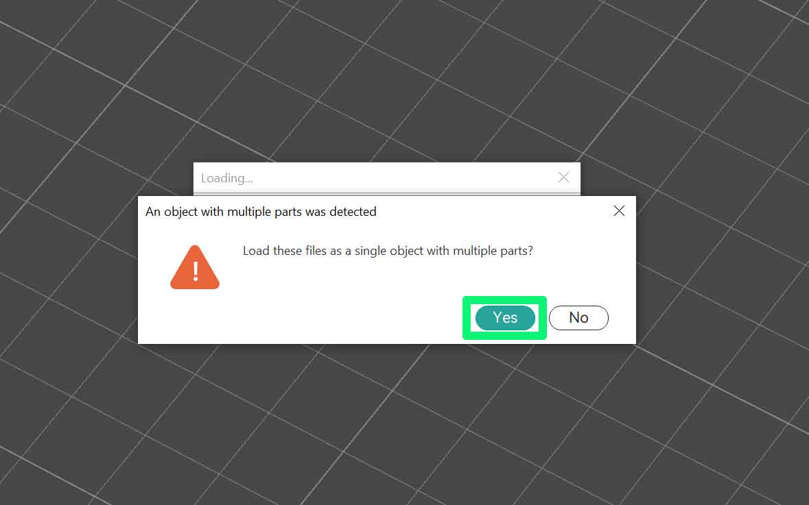
The models will load and will be grouped together, so they can both be moved without losing their positions relative to each other.
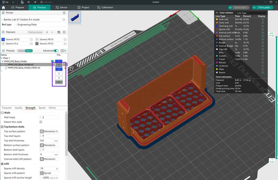
If using an AMS, the colors for the mesh and main object can be changed by selecting the object, and then clicking (or clicking several times) on the "Fila." box, which should show the color of the default filament loaded. From here, there will be a dropdown box where other colors can be selected. The images below are for a different model, but the idea is the same:
If using an AMS, the colors for the mesh and main object can be changed by selecting the object, and then clicking (or clicking several times) on the "Fila." box, which should show the color of the default filament loaded. From here, there will be a dropdown box where other colors can be selected. The images below are for a different model, but the idea is the same:
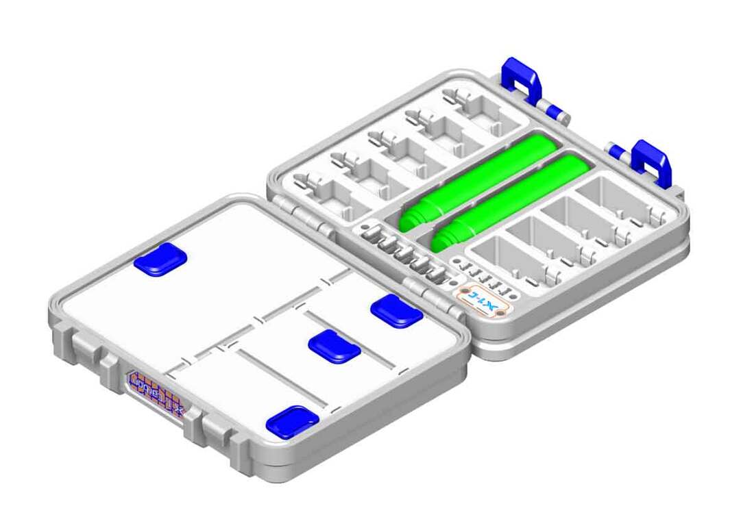
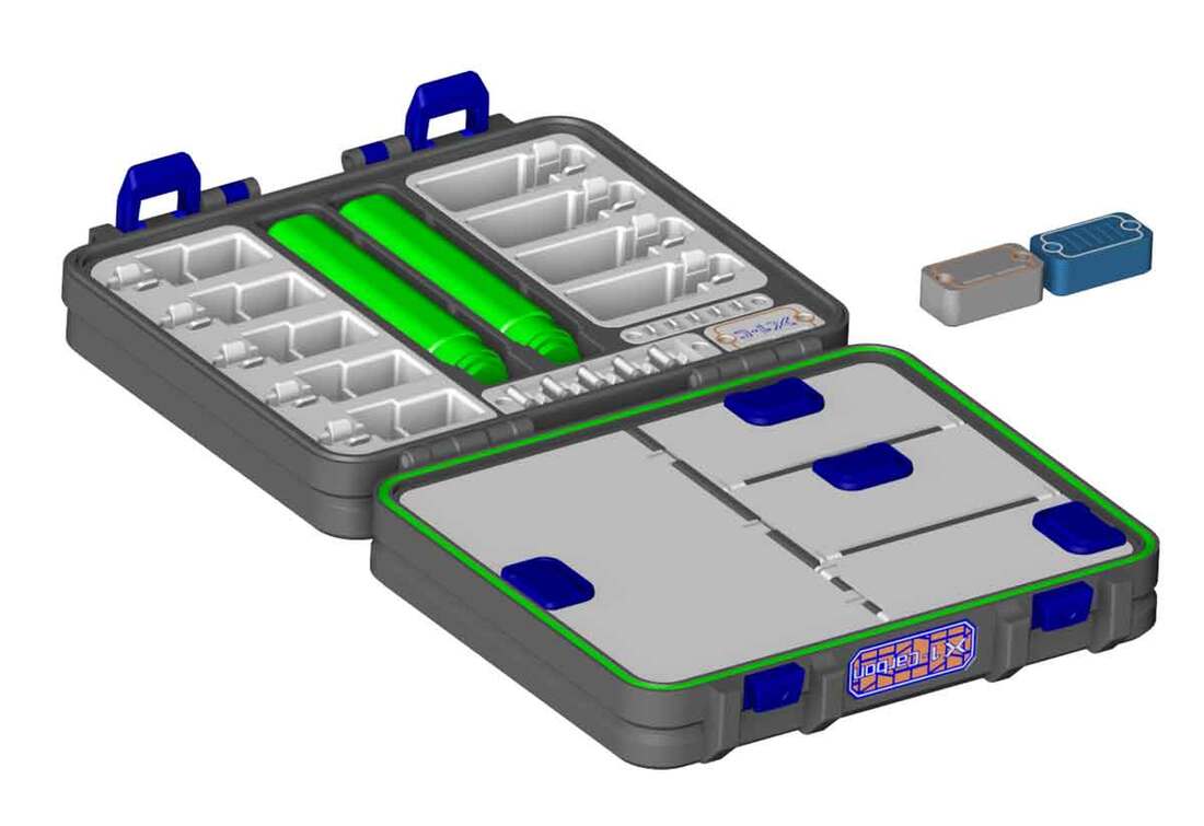
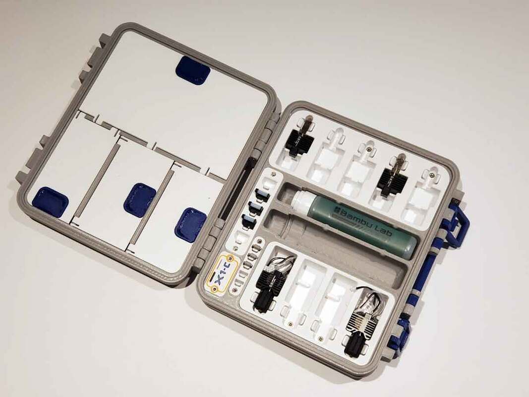
Putting it Together
Assembly is pretty straightforward, there are no heat set inserts, and everything is assembled with screws. I recommend wearing eye protection to assemble this, since there are some parts (such as the doors) need to snap in, and most folks only have one spare eye.
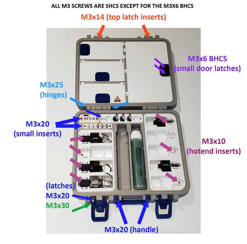
The guide below may help to determine which screws go where:
The guide below may help to determine which screws go where:
Step 1 - The Handle
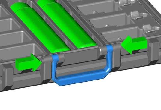
The handle installs with the following hardware:
(2) M3 x 20mm SHCS
(2) M3 x 20mm SHCS
Step 2 - Latches
To assemble the latches, the following hardware is required:
(2) M3 x 14mm SHCS
(2) M3 x 20mm SHCS
(2) M3 x 30mm SHCS
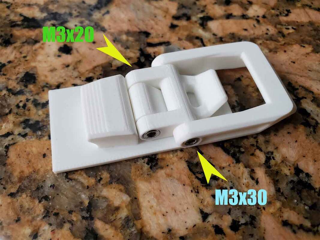
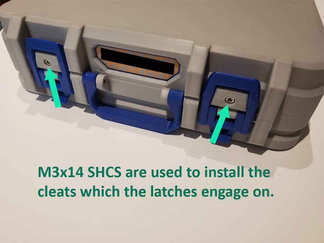
The latches have a left and right side, and there is an access hole in the case, which will be used to install the M3x20mm screw. The access hole for the M3x20mm screw is tight, but the head of the screw should fit through. The M3x30mm screw just installs as shown in the pic below (on the left).
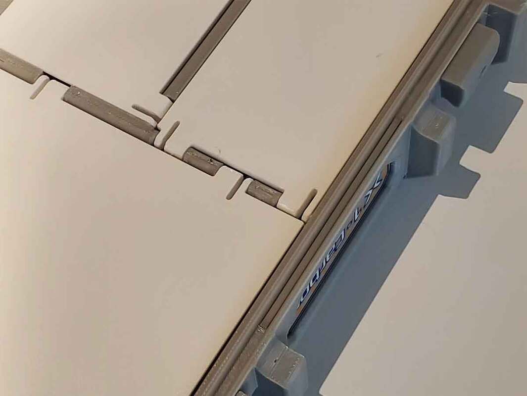
The cleat, which the latches engage on the Top of the case also needs to be installed. This part is "Bambu_ToolKit-7D_TOP_CLEAT.stl", and can be used on either side (print two of them). The cleat will slide into dovetails in the top of the case, and when fully installed, it needs to be secured with one M3x14mm SHCS screw. Check that the cleat and the dovetail are free of stringing or blobs before installing, and if it's too tight, lightly sand the cleats just a bit (don't force them in since they could crack the case or get stuck). The pic below (on the right) shows the M3x14mm screw installed in the cleat.
(2) M3 x 14mm SHCS
(2) M3 x 20mm SHCS
(2) M3 x 30mm SHCS
The latches have a left and right side, and there is an access hole in the case, which will be used to install the M3x20mm screw. The access hole for the M3x20mm screw is tight, but the head of the screw should fit through. The M3x30mm screw just installs as shown in the pic below (on the left).
The cleat, which the latches engage on the Top of the case also needs to be installed. This part is "Bambu_ToolKit-7D_TOP_CLEAT.stl", and can be used on either side (print two of them). The cleat will slide into dovetails in the top of the case, and when fully installed, it needs to be secured with one M3x14mm SHCS screw. Check that the cleat and the dovetail are free of stringing or blobs before installing, and if it's too tight, lightly sand the cleats just a bit (don't force them in since they could crack the case or get stuck). The pic below (on the right) shows the M3x14mm screw installed in the cleat.
Step 3 - The Hinges
To install the hinges, the following screws are required:
(4) M3 x 25mm SHCS
Alternatively, (2) M3x45mm (or possibly 50mm) SHCS can probably be used if there are no M3x25mm screws handy. M3x20mm screws may work, but I would not recommend them, since they will not have much to screw into. To install the hinge screws, first assemble the top and bottom together so the holes in the hinge line up. Then install the screws from each side of the hinge. I used an Allen key, but switched to a flexible shaft driver, which made installing the inside screws much quicker.
Step 4 - The Hotend Holders
The hot end holders install with the following hardware:
(7) M3 x 10mm SHCS
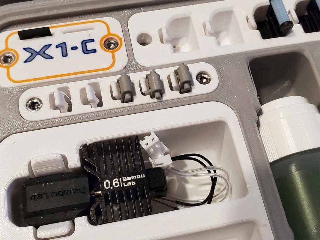
The hotend holders are pretty straightforward. But any printing errors or boogers need to be cleaned off before fitting, since it's a snug fit (though it should not require sanding unless the surface quality is poor). The screws should not be over-tightened, but if they are, the holders can simply be glued in place using some superglue (or add some glue to the screw holes if they get stripped out). However, unless glue is needed due to a stripped screw, I'd not use it. If there is damage later, the modules cannot be replaced if they are glued in.
(7) M3 x 10mm SHCS
The hotend holders are pretty straightforward. But any printing errors or boogers need to be cleaned off before fitting, since it's a snug fit (though it should not require sanding unless the surface quality is poor). The screws should not be over-tightened, but if they are, the holders can simply be glued in place using some superglue (or add some glue to the screw holes if they get stripped out). However, unless glue is needed due to a stripped screw, I'd not use it. If there is damage later, the modules cannot be replaced if they are glued in.
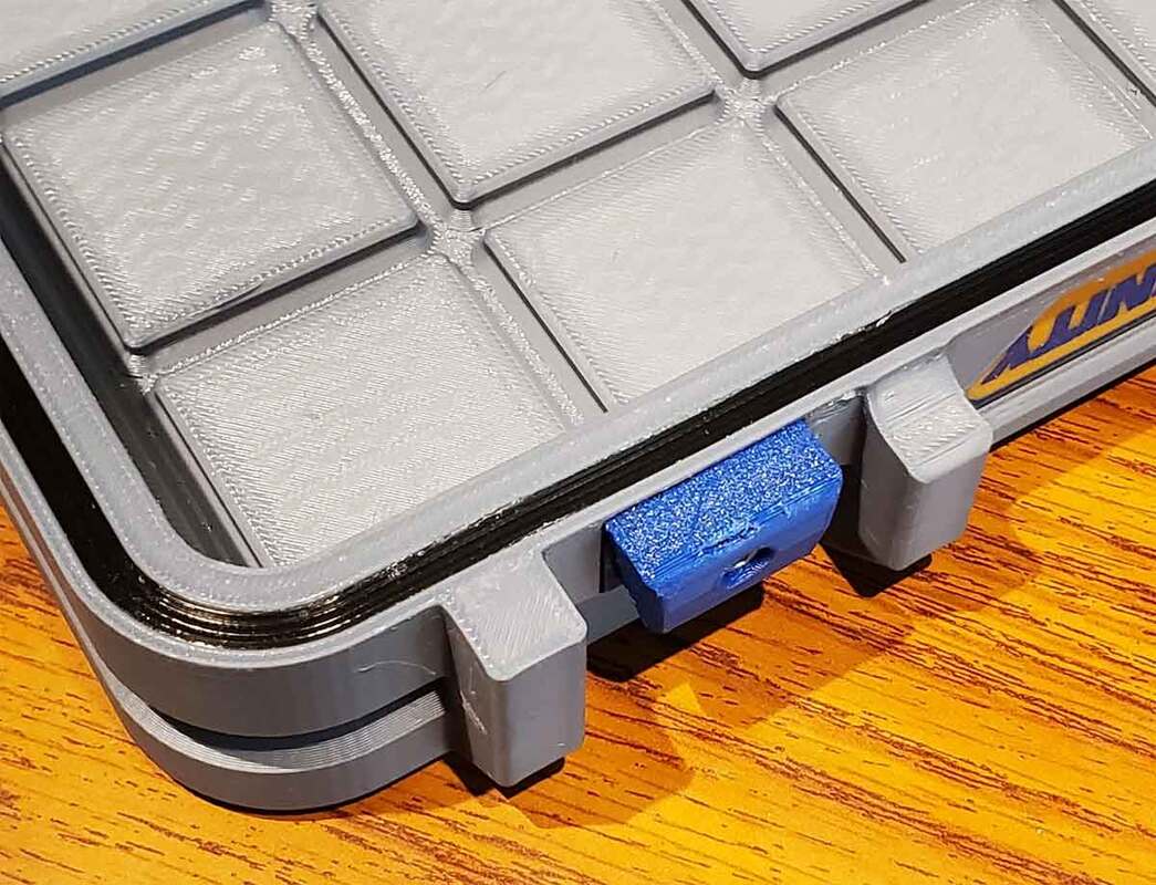
Step 5 - The Wiper, Cutter and MicroSD Modules
The following hardware is needed to install the smaller modules:
(6) M3 x 20mm SHCS
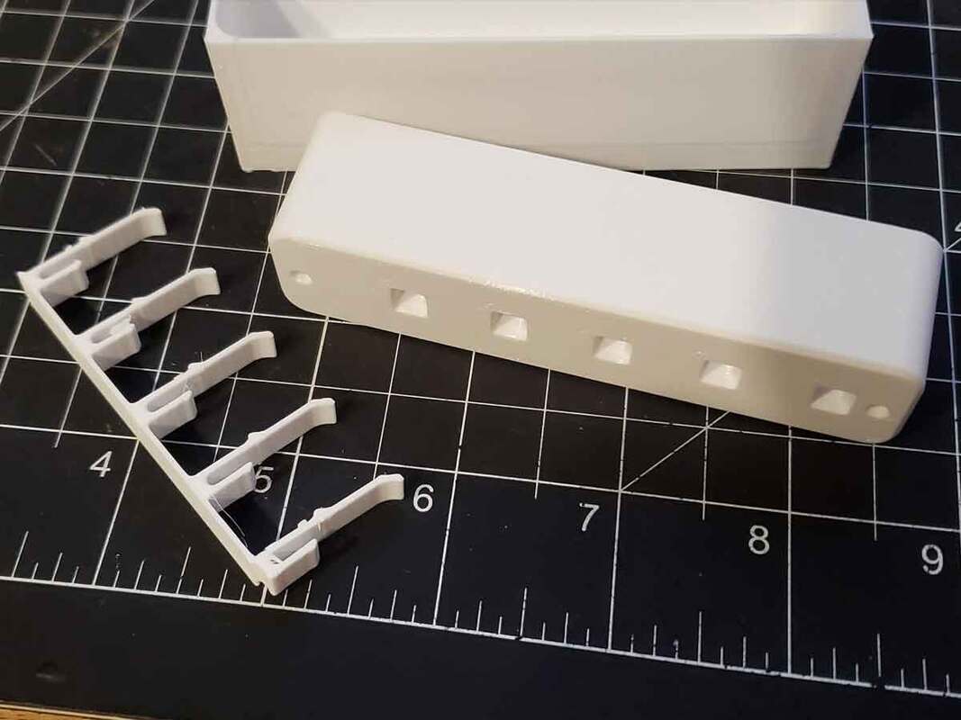
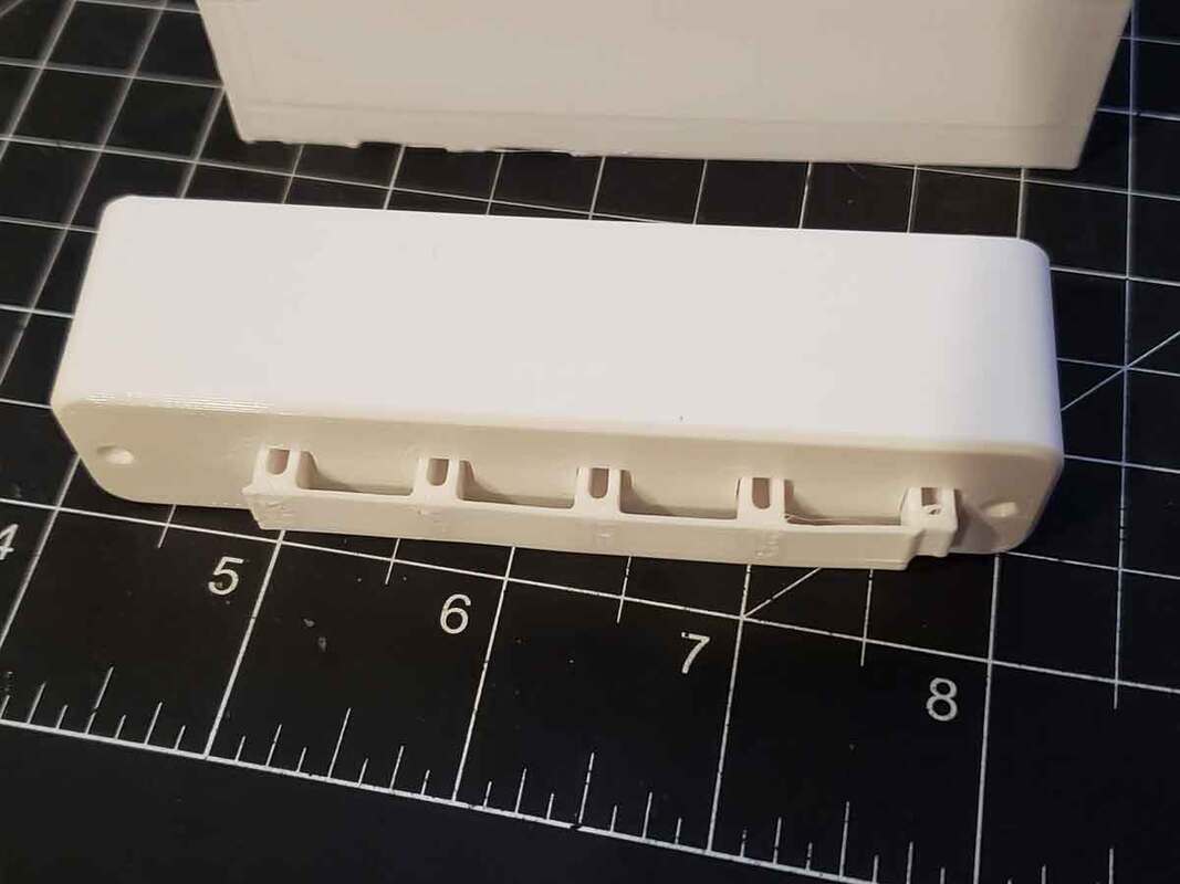
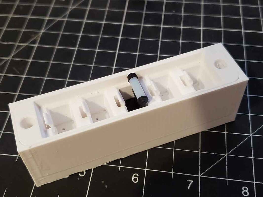
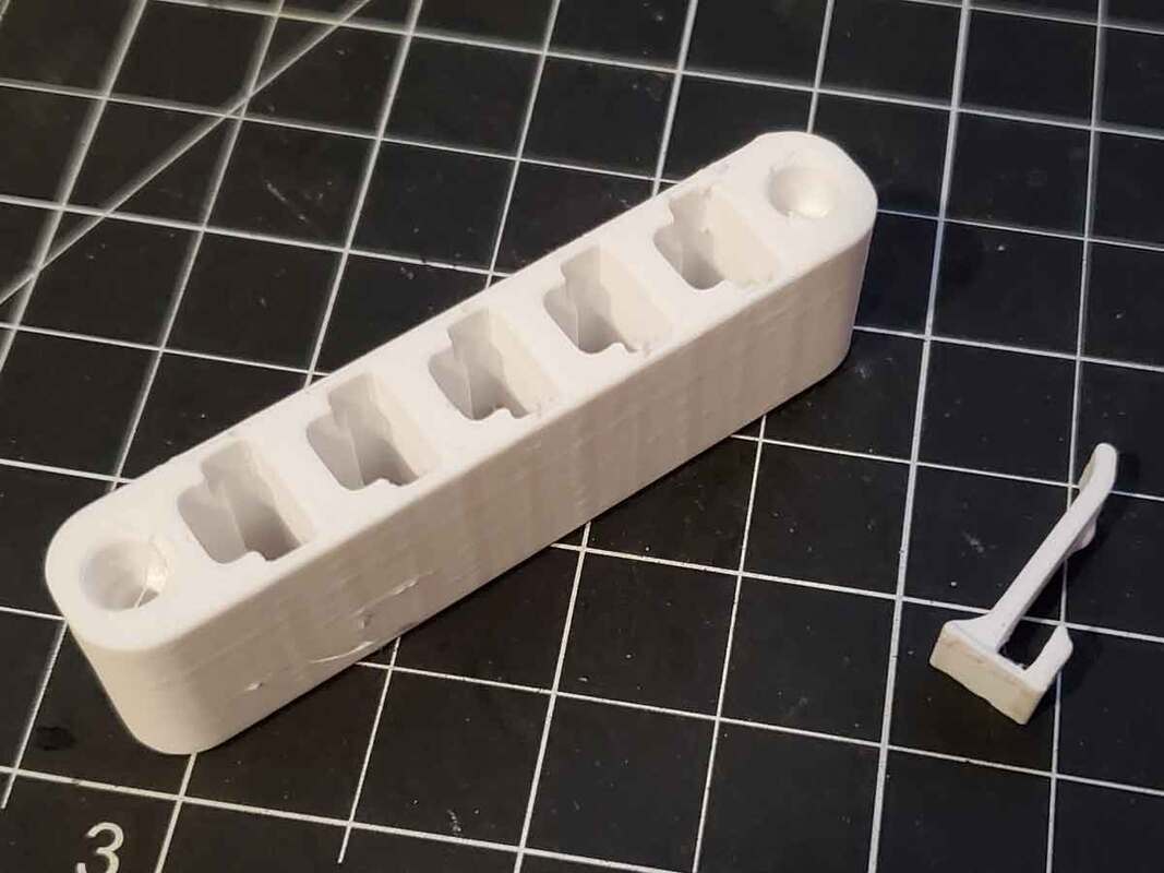
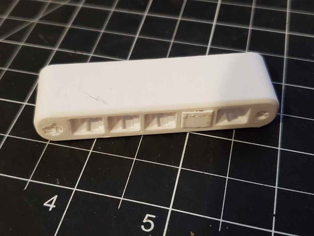
The wiper and cutter modules have been updated due to several folks letting me know the tabs were breaking. I didn't have that issue with mine, but could see how it could be improved. The updated models now have separate tabs, and can print flat, which will give them the most strength against snapping when bending. They are assembled as shown in the pics, prior to being installed in the case using the M3x20 screws.
Each module gets two screws, and the same suggestions apply as for the hotend holders. They should be smooth before installing, since they are a snug fit. The parts orientation is also important to observe. They go in as shown in the pic below.
(6) M3 x 20mm SHCS
The wiper and cutter modules have been updated due to several folks letting me know the tabs were breaking. I didn't have that issue with mine, but could see how it could be improved. The updated models now have separate tabs, and can print flat, which will give them the most strength against snapping when bending. They are assembled as shown in the pics, prior to being installed in the case using the M3x20 screws.
Each module gets two screws, and the same suggestions apply as for the hotend holders. They should be smooth before installing, since they are a snug fit. The parts orientation is also important to observe. They go in as shown in the pic below.
Step 6 - The Top Lid Doors and Latches
The doors in the top lid will require the following hardware:
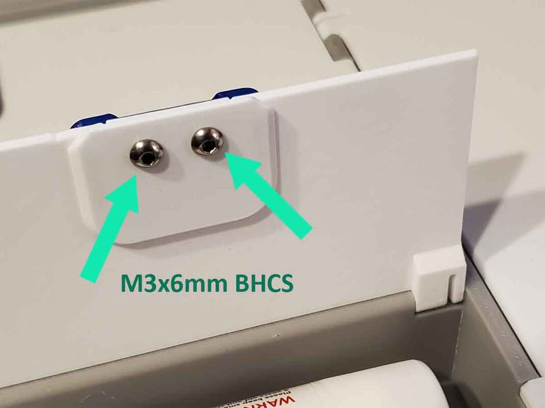
(8) M3 x 6mm BHCS
To assemble the doors (which go in the top lid), first take note of the orientation of the doors. The top side should be flat (the side that printed against the bed). The latches use the following parts (4 of each are needed):
(4) Bambu_ToolKit-7D_TOP_DOOR_LATCH_UPPER.stl
(4) Bambu_ToolKit-7D_TOP_DOOR_LATCH_LOWER.stl
The latches should be assembled on the doors first. The bottom latch part should be installed first, and then screwed together with the top part, as shown in the pic below.
Once the latches are installed, the doors can be installed in the top by snapping their hinges into the top. Care should be taken not to snap the hinges, and again use some safety glasses here in case a part snaps off. There should be enough flex in the hinges to push them in, but a thin flat head screwdriver can be used to assist if necessary. These parts should be printed in PETG, since they require some flexibility to get the hinges installed (PLA is too brittle).
Once the doors are in, check that they latch correctly. If they do not, the pockets where the latches lock in the top of the case may need to be cleaned of any stray material.
Once the doors are in, check that they latch correctly. If they do not, the pockets where the latches lock in the top of the case may need to be cleaned of any stray material.
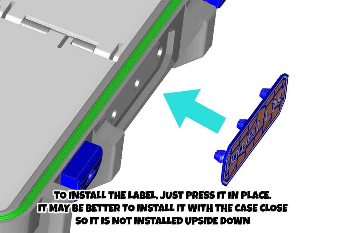
Step 7 - The Case Label
This one is hardly a step, but I did not want to leave it out. The case has a label frame on the front near the handle. To install the label, first check the orientation of the label. It may help to close the case before installing the label, which will make the orientation obvious. Check that the holes in the case are free of blobs and that the posts on the label are also free of blobs. Then just press it in place, until the posts snap in place.
Note that the latest version 2.1 design only uses 2 posts (unlike the 3 posts shown in the pic).
Note that the latest version 2.1 design only uses 2 posts (unlike the 3 posts shown in the pic).
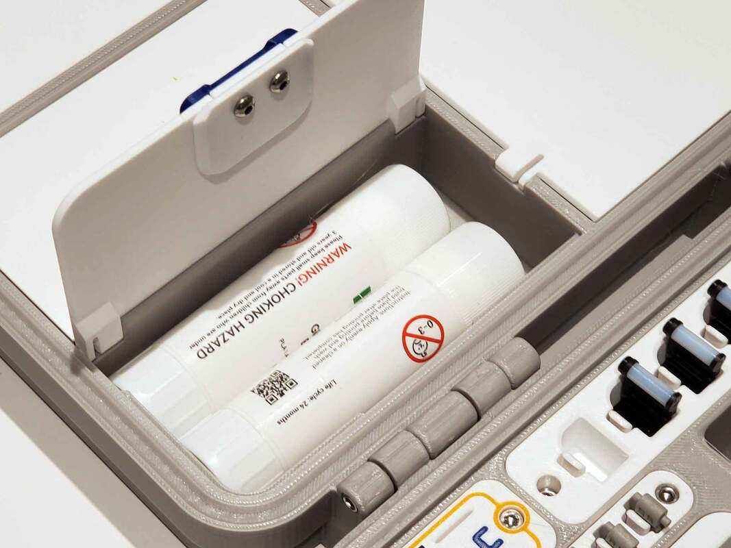
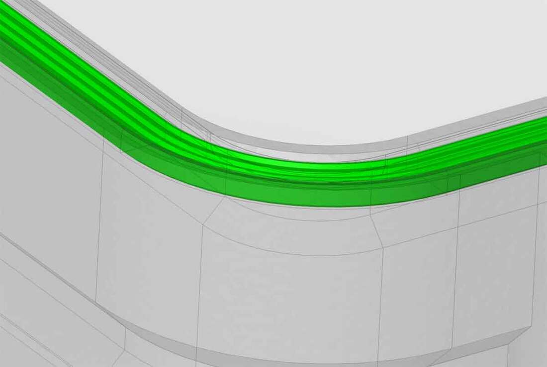
Step 8 - Install the Gasket (if using the Top with a Gasket)
I did not take pics of this step, but the gasket snaps into place in the top. As before, make sure there are no blobs or other pieces in the groove where the gasket goes (or on the gasket), before attempting to install it. To press the gasket in place, I found that the blunt end of a sharpie marker worked well as a tool to seat it. I also used some clear silicon sealant (specifically Gorilla Clear Silicone Sealant), in the groove prior to installing the gasket, which I applied with a cotton swab. The silicone is optional, but I think it may help, since there are always gonna be imperfections in a 3D printed part (which the silicone can help fill).
Thats It, Enjoy Your Bambu Labs Spare Parts Case!
If you like this, please consider posting a make on Printables or MakerWorld. If you want to support my 3D printing addiction, you can help by checking out some of the Amazon affiliate links for parts in this guide, or you can even Buy me a Coffee using the link below.
Thanks for looking!

This guide was updated 2/11/2024 for the current version 2.1 models.
