Making My Remix of Ocie's 21-Cup Filament Silos
FIRST AND FOREMOST - SAFETY - this design uses springs and although they are small and not very strong, but currently there is no replacement for an eye so why take the risk? Please wear safety glasses when making this.
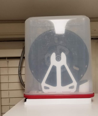
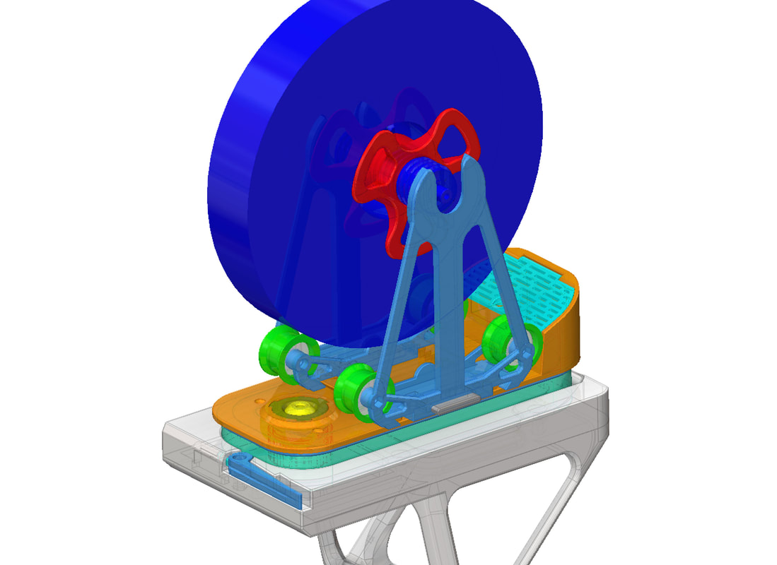
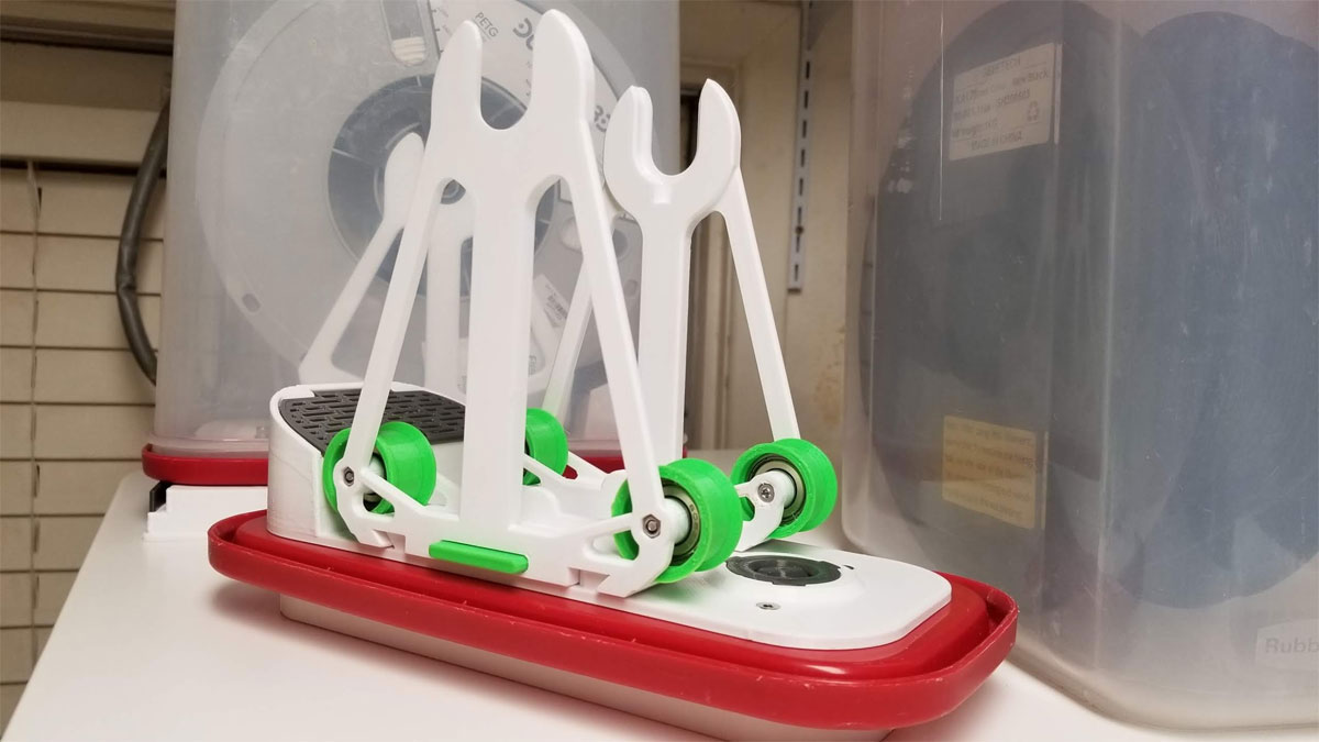
This is a simple guide on how to assemble my remix of Ocie's 21-Cup Filament Silos. The idea behind this remix is to incorporate several features that were lacking in my current setup, which already uses similar Rubbermaid 21-Cup Storage containers. Ocie's design is very well documented and he kindly included the STEP files which is a huge benefit. I also liked the use of dovetails to hold the spool rollers, and thought I could design a center axis spool holder as well, which evolved into a either a combo center axis and roller, or roller only design for the bogies. Further along when testing this, I decided to go a different route than using dovetails for adjusting the bogies. Now instead, I am using a ratcheting indexer to adjust them.
Although I started off wanting to make a simple remix of Ocie's original design, I ended up using very little of the original design, but I did use the dimensions for the base plate and definitely a lot of the inspiration came from iterating a design which was based on his work. Some of the key elements which I adapted to the design include the following:
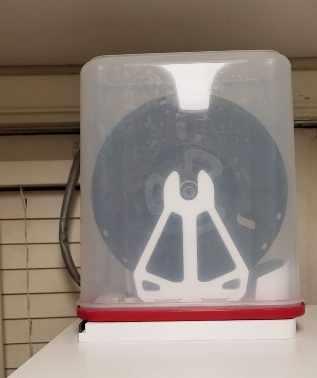
One major difference between this design and Ocie's original is that mine was designed for the 21 Cup Rubbermaid containers with the milky plastic and the solid red lids, not the crystal clear containers with a window top like Ocie used. Because of this, my remix has a slightly larger base which mounts to the lid. I suspect that this remix will still work with the clear window lids, but it may not fall into place on those as nicely. I have been unable to find the crystal clear Rubbermaid containers around here and question if they were discontinued, but I can still get the type with the solid red lids (but I have enough right now anyway).
This design is tailored to my particular use, but I figure there are enough folks with enclosures, or have some need for a similar system of a fixed base and dry boxes which can be mounted, and fixed in place until the next one needs to be switched in it's place. I have used this several times, though have not permanently mounted it on my printer since I'm still finalizing the orientation I want to use. I think it could be temp mounted using some 3M Command strips or more permanently using screws or glue of course. The latching base really holds the container well, and I suspect it could even be mounted upside down and work as well, though it would require a different roller design. I also designed a flexible base "gasket" (to be printed in flex filament) that is not designed for sealing but more for making a cleaner looking install. I tried printing the flexible base but it destroyed my PEI sheet since I ran out of hairspray to use as a release agent. I may not use it anyway, but will include the file with the rest. That part could also be printed in regular filament in a contrasting color to give it a cool trim as well (something I may try).
There is only one thing that I don't particularly like about this design. I find that I sometimes need to open the box to start the spool which can be somewhat mitigated by remembering to bend a bit of filament before installing the cap (to keep it from backing out the hole). Having a bit of bowden tube extend inside the enclosure of the case also can help with this since it helps hold the filament through friction so it doesn't tent to suck back into the container. Other than that I'm pretty happy with this, and it took a while to fine tune things, with several iterations printed and parts adjusted based on testing, to get something that I feel fine with posting for other folks to try out.
Note that some of the pics here are of an older design, but not so old that the instructions no longer apply.
This is a simple guide on how to assemble my remix of Ocie's 21-Cup Filament Silos. The idea behind this remix is to incorporate several features that were lacking in my current setup, which already uses similar Rubbermaid 21-Cup Storage containers. Ocie's design is very well documented and he kindly included the STEP files which is a huge benefit. I also liked the use of dovetails to hold the spool rollers, and thought I could design a center axis spool holder as well, which evolved into a either a combo center axis and roller, or roller only design for the bogies. Further along when testing this, I decided to go a different route than using dovetails for adjusting the bogies. Now instead, I am using a ratcheting indexer to adjust them.
Although I started off wanting to make a simple remix of Ocie's original design, I ended up using very little of the original design, but I did use the dimensions for the base plate and definitely a lot of the inspiration came from iterating a design which was based on his work. Some of the key elements which I adapted to the design include the following:
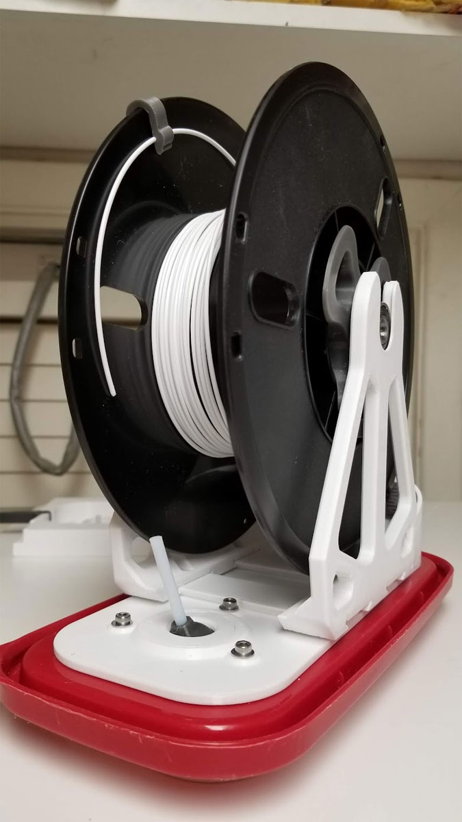
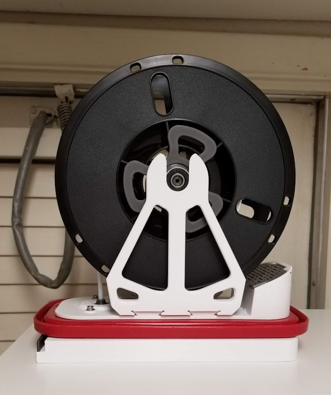
- A center axis spool holder based off my remix of ButchJa's Universal Filament Spool Holder. This also incorporated an element of BradM's Rubbermaid 21 Cup Dry Box Spool Holder (I used his design for the Bearing Holder).
- A storage compartment for some silica gel or whatever :D
- My "Improved" version of my Filament guide for dry box, with o-ring screw cover, which uses an O-ring to seal a ball though which the filament runs through. The idea is the ball allows for some variation in the angles the filament may go into the bowden tube when it rolls off the spool. There is also a cap which can seal with a 2nd O-ring and is used to seal the entire container when not in use.
- The ratcheting mechanism was taken from my Equate 34oz or Target 32oz Hand Sanitizer holder - Anti-theft Wall Mount.
- And finally, there is a latching base, which holds the container and is intended to be mounted in a fixed location such as a shelf or in my case on top of my printer enclosure. The latch was adapted from my Raspberry Pi 4 latching case and my Latching Under Desk Slide Out Mount For A Lenovo M700 (or M93p) Tiny PC.
- There is a opening which should be wide enough to accommodate many different filament pass through setups, including the one I use. I also designed a mount for a 2020 rail such as the top cross rail on an Ender3, however I have no plans to test that design since I cannot use it with my current setup due to a cabinet above my Ender3. I will however post that as a work in progress remix.
One major difference between this design and Ocie's original is that mine was designed for the 21 Cup Rubbermaid containers with the milky plastic and the solid red lids, not the crystal clear containers with a window top like Ocie used. Because of this, my remix has a slightly larger base which mounts to the lid. I suspect that this remix will still work with the clear window lids, but it may not fall into place on those as nicely. I have been unable to find the crystal clear Rubbermaid containers around here and question if they were discontinued, but I can still get the type with the solid red lids (but I have enough right now anyway).
This design is tailored to my particular use, but I figure there are enough folks with enclosures, or have some need for a similar system of a fixed base and dry boxes which can be mounted, and fixed in place until the next one needs to be switched in it's place. I have used this several times, though have not permanently mounted it on my printer since I'm still finalizing the orientation I want to use. I think it could be temp mounted using some 3M Command strips or more permanently using screws or glue of course. The latching base really holds the container well, and I suspect it could even be mounted upside down and work as well, though it would require a different roller design. I also designed a flexible base "gasket" (to be printed in flex filament) that is not designed for sealing but more for making a cleaner looking install. I tried printing the flexible base but it destroyed my PEI sheet since I ran out of hairspray to use as a release agent. I may not use it anyway, but will include the file with the rest. That part could also be printed in regular filament in a contrasting color to give it a cool trim as well (something I may try).
There is only one thing that I don't particularly like about this design. I find that I sometimes need to open the box to start the spool which can be somewhat mitigated by remembering to bend a bit of filament before installing the cap (to keep it from backing out the hole). Having a bit of bowden tube extend inside the enclosure of the case also can help with this since it helps hold the filament through friction so it doesn't tent to suck back into the container. Other than that I'm pretty happy with this, and it took a while to fine tune things, with several iterations printed and parts adjusted based on testing, to get something that I feel fine with posting for other folks to try out.
Note that some of the pics here are of an older design, but not so old that the instructions no longer apply.
Bill of Materials
Note - some of the links below are Amazon Affiliate Links. This means that, at zero cost to you, I will earn an affiliate commission if you click through the link and finalize a purchase. This will help to support this site and pay for more Stoopid Stuff. I tried to link to the actual items I have bought, or if they are not available, similar items which I would buy based on value, but they are by no means the only options that will work.
The following parts are needed to make the basic spool holder (without the top mounting base)
The following parts are needed to make the basic spool holder (without the top mounting base)
- Rubbermaid 21-Cup Storage container
- 4x 608 "skate" bearings (or 6 if you make the combo center axis roller)
- 5x M3x12mm (or 14mm) flat head screws
- 4x M3x20mm socket or round head screws (to hold the bearings on the rollers)
- 9x M3 lock nuts
- 1x M3x14mm or longer socket or cap head screw and optional M3 washer (used to secure the desiccant lid)
- 1x M3 nut (used to secure the desiccant lid)
- 3 springs from a clicky pen. Specifically I used a pen sprint found on Ebay which is called "spring spare ball pen part 424" (but any cheap clicky pen spring will work - but the pen won't :D)
- 5x flat head wood screws of no more than 5mm in diameter to hold the base to whatever it will be mounted to. If using the 2020 rail top mount these are not needed.
- 1x P18 17.8 (ID) x 2.4mm O-ring (other similar sizes should also work). I used an older version (91512) of the following O-ring kit from Harbor Freight which has the required O-rings:
https://www.harborfreight.com/397-piece-metric-o-ring-assortment-67580.html - 1x 22 (ID) x 3mm O-ring or 22.1 (ID) x 3.5mm (preferred size) O-ring for the inside of the cap - use the larger one if you can find it.
- 1x small paperclip
If you plan to try out the (untested) top mount for 2020 rails (this is not yet posted to Thingiverse and these may change), the following will also be needed:
- 5x M4x12mm (or 14mm) flat head screws
- 5x M4 lock nuts
- 3x M4x10mm button or cap head screws
- 3x M4 washers
- 3x M4 t-nuts
Now to building this thing:
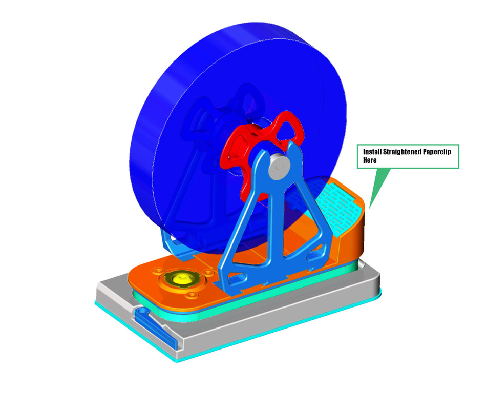
Step 1: Install the Lid on the Silica Gel Compartment
Get a smaller size paper clip and bend it as straight as possible, then thread it into the hole on the back of the desiccant compartment and it's lid, to form a hinge. Then I trimmed off the excess with the edge cutters.
Step 2: Assemble the Base
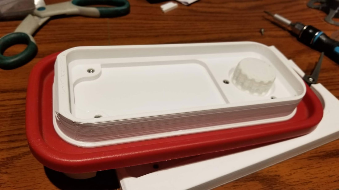
The first step before assembling the base is to install all the M3 lock nuts. There are 5 which go into the bottom of the base which is the large part which you can see from the outside. The lock nuts should be oriented in the correct direction and using a longer M3 screw to set them in helps. They should go in snug but not too tight that it's impossible to install. If you run into a problem where they just won't go in, you can try heating them to melt them in, though that will also mess up the plastic insert in the nuts so be aware of that. If they don't fit, try calibrating flow and e-steps (I would do this beforehand but I'm assuming the parts are already printed with this guide).
There is one regular M3 nut which installs in the base (Spool_holder-QR-9M-BASE-A.stl) and holds the cover on the desiccant tray. Some superglue should be used to help hold this in, and it can be a bit tricky to install, but I used a longer M3 screw to start it, then pulled it into position with the glue and then used the M3x16mm screw to seat it. This screw is optional but will secure the lid if using loose silica gel pellets.
There is one regular M3 nut which installs in the base (Spool_holder-QR-9M-BASE-A.stl) and holds the cover on the desiccant tray. Some superglue should be used to help hold this in, and it can be a bit tricky to install, but I used a longer M3 screw to start it, then pulled it into position with the glue and then used the M3x16mm screw to seat it. This screw is optional but will secure the lid if using loose silica gel pellets.
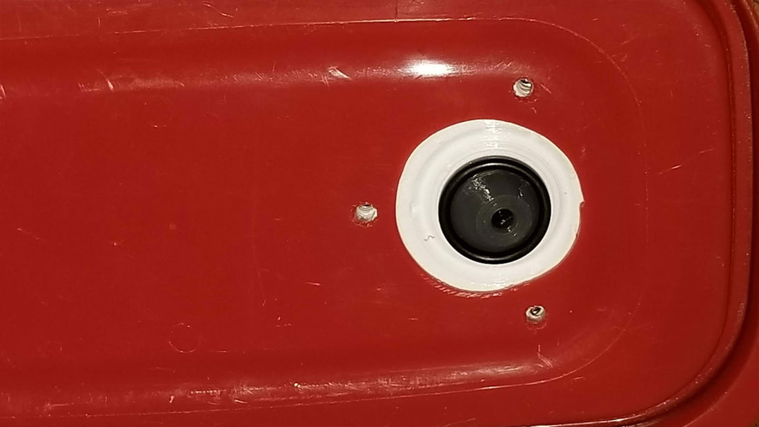
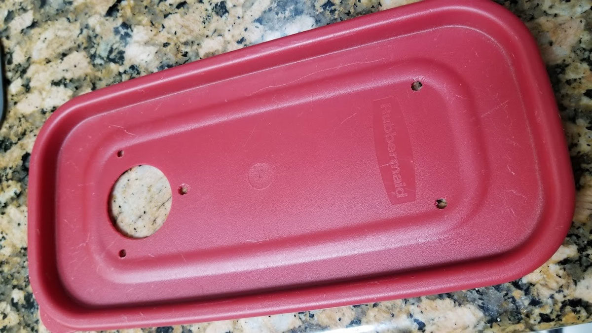
Once the nuts are installed, find the center part, which is the thin part with the strange hole to mount the filament pass through ball. This part has a cut out which matches up with the topology of the lids on my Rubbermaid 21 cut containers, which do not have a clear window. I used the thinner center part as a guide to mark the holes needed to be drilled and cut in the lid. To cut and drill the lid, I used some small bits to start the holes and ended with a 1/8" bit for the five small holes, and I used a step bit to drill the largest hole, though it can also be cut by hand if done carefully. Then clean up any burrs in the plastic left behind from drilling and test fit it again to make sure the hole for the pass through is aligned OK.
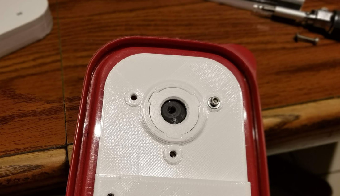
Once the holes are drilled, install the circular insert with the three protrusions in the top piece. In the thin center piece, install the P18 17.8 x 2.4mm O-ring and the ball on top of it. Then carefully assemble the sandwich of the top, lid, center and bottom of the base. The insert in the top piece will mate with some grooves in the center part and help align things. It can help to set a couple of the M3x12 flat head screws in through the top and get the lid sandwiched first (which will hold the ball in place), and then putting the bottom part on and finally getting a few of the screws heightened down most of the way to make the rest easier to align and install. Note that the pics show M3x12mm cap head screws, but the newest design requires flat head screws. When it is assembled the ball should move smoothly with just a very small bit of resistance, since it rides on the o-ring.
Step 3: Assemble the Latching Mount
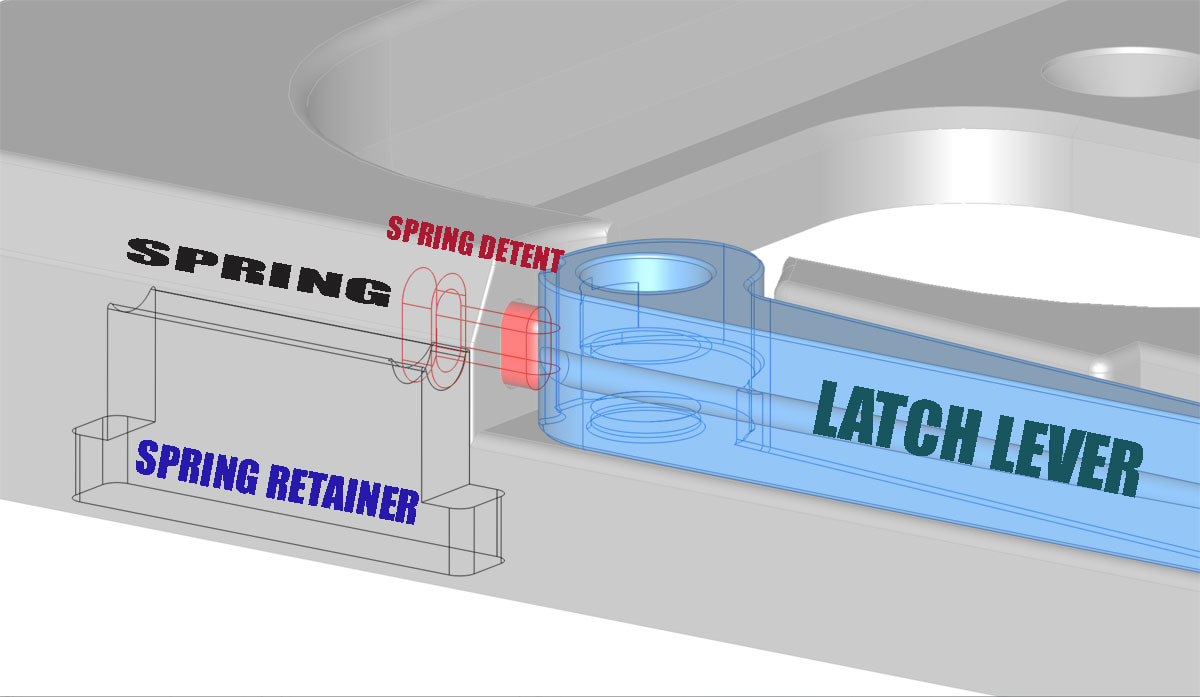
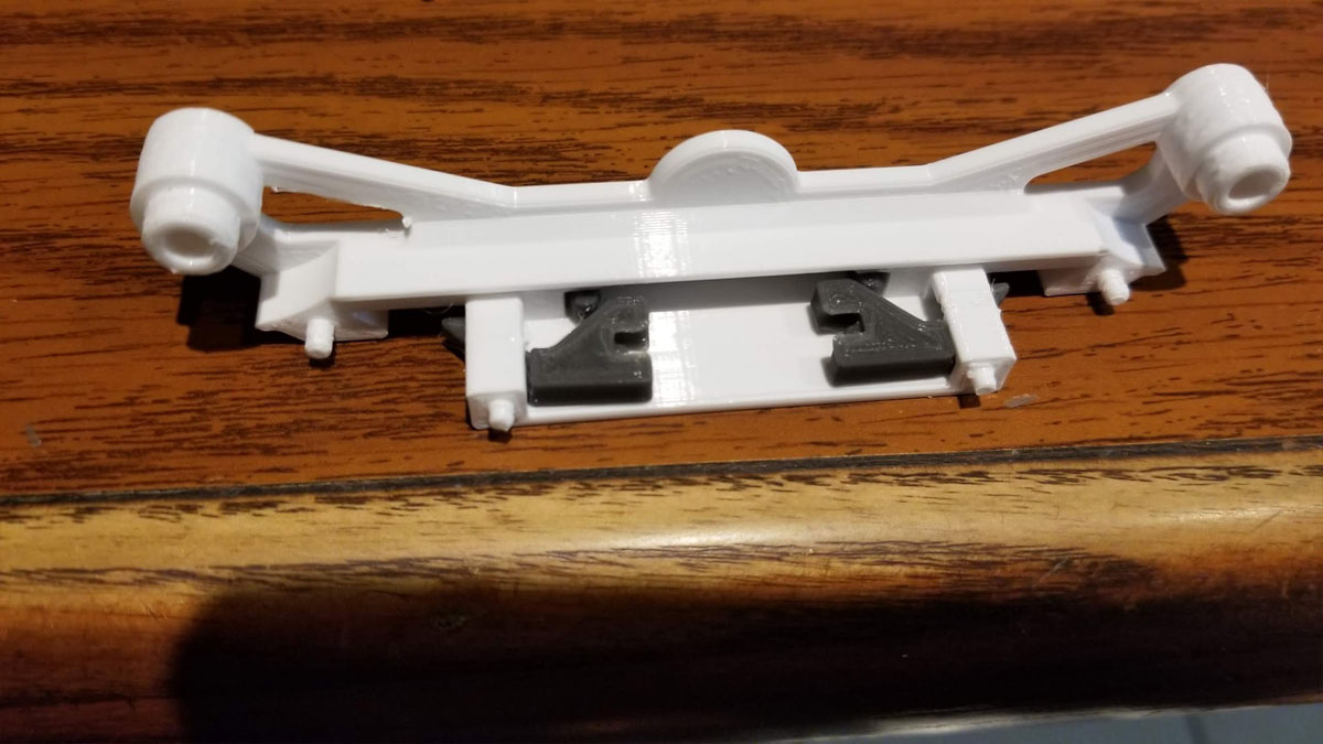
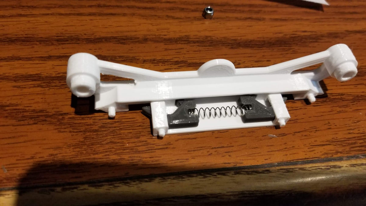
The final step is to assemble the latching base. This part has 5 components; the base, the lever, a spring from a clicky ball point pen, a detent which the spring presses against, and a spring retainer. Since the spring is... a spring and to install it requires it to be compressed, please wear some safety goggles. It also is a good idea to dry fit the spring detent into it's hole and make sure it slides freely. If necessary clean the hole the detent goes into to make it operate freely.
To install the spring, I installed the detent in the hold (before I installed the lever), and then used a screwdriver to work the spring into position. It was the most difficult part of the build but it's really not that bad. I think perhaps using a Q-tip or the end of a cap head screw that would fit in the groove may be better tools for setting the spring in it's groove. Before installing the spring retainer make sure that the lever operates smoothly. but if it does not check that there are no supports or rough surfaces on the lever or the post it goes on. Once the spring is in place and the lever detent is operating smoothly, the spring retainer goes in. This part was a friction fit but it can be glued if it will not be mounted in a way that will hold it in the base.
To install the spring, I installed the detent in the hold (before I installed the lever), and then used a screwdriver to work the spring into position. It was the most difficult part of the build but it's really not that bad. I think perhaps using a Q-tip or the end of a cap head screw that would fit in the groove may be better tools for setting the spring in it's groove. Before installing the spring retainer make sure that the lever operates smoothly. but if it does not check that there are no supports or rough surfaces on the lever or the post it goes on. Once the spring is in place and the lever detent is operating smoothly, the spring retainer goes in. This part was a friction fit but it can be glued if it will not be mounted in a way that will hold it in the base.
Now that the spring, retainer and detent are installed, the lever can be installed. It goes in with a M3 locknut in the base and a M3x12 or M3x14mm cap head screw and an M3 washer. Note that some M3 washers are different sizes, but it should work for washers with diameter up to 7.3mm. The washer retains the lever so it is important to use it.
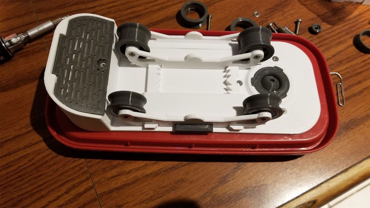
Now the base can be mounted with screws or tape. To use it, just set the back of the container in the base first, then rotate it down with the latch open. When it is in place throw the latch closed and it should stay put.
As an aside, if the tiny spring detent did not print well, try printing it with another part or several of the small detents about an inch away from each other on the build surface. The reasoning is that when printing very small parts, the individual layers may not get enough time to cool and that results in poor quality prints. You could alternatively use the minimum layer time and "lift head" settings in Cura to avoid this problem too.
As an aside, if the tiny spring detent did not print well, try printing it with another part or several of the small detents about an inch away from each other on the build surface. The reasoning is that when printing very small parts, the individual layers may not get enough time to cool and that results in poor quality prints. You could alternatively use the minimum layer time and "lift head" settings in Cura to avoid this problem too.
Step 4: Assemble the spool rollers bogies or the combo holder
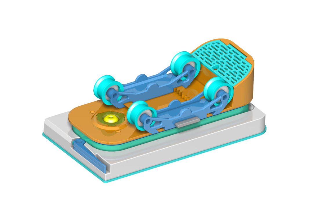
The spool roller bogies have several parts which go together as follows:
- install he bearings on one side of the roller, then install the "tires" on the bearings.
- Clean up the pawls and button to remove any "elephant foot" and also clean up the holes they will go through, to make sure there is as little friction in their movement as possible.
- Install the button and pawls inside the larger side of the roller as shown in the pic above (left). The Pawls go in only one way.
- Install the pen spring between the pawls. It may be easier to remove the pawls and install the spring on one side and then install them. When done it should look like the pic above (right).
- Push both sides of the roller holder together, the parts should close together tightly.
- Install the M3 locknuts (in the button side) and M3x20mm screws in the holes through the center of the bearings on each side of the holder.
- Test the function of the button and pawls, it should operate smoothly without sticking.
- Install the bearing holder onto the base, use the button to release the pawls when adjusting it.
If using the the central axis spool holder there are a couple more steps:
- Install the bearing insert in the base of the larger part of the spool holder
- Next install 608 bearings on both ends.
- When assembled to a spool, it just drops into the spool holder arms and it's ready to go (again note that some of the pics show an older design but the current design is similar).
Step 5 - Put the container on the lid ;-)
Info for the optional (untested) 2020 rail top mount
The 2020 rail mount is as noted untested. I am planning to add that as a remix and I hesitate to post instructions for something I have not built so I will wait on feedback before I do so. However I can say that the 2020 rail mount was designed to mount to the base using 5x M3x12mm (or 14mm) flat head screws and then to the 2020 rail using 3x M4x10mm cap or button head screws with t-nuts and washers. There is a wire chase in the mount in case some small LED could be found to add a simple light, however this idea is not fully developed and any LED would need to be low power so as not to get warm and possibly weaken the plastic. I am also not sure about the strength of the mount so I would also need to get feedback on that, but I would print it with at least 3 and probably 4 shells and high (>30% gyroid) infill, with the filament run just a bit on the hot side to make sure there is good layer bonding.
