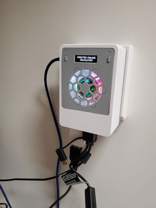
Making The Button Module For Sneaks' Modular Snap Together Raspberry Pi Case
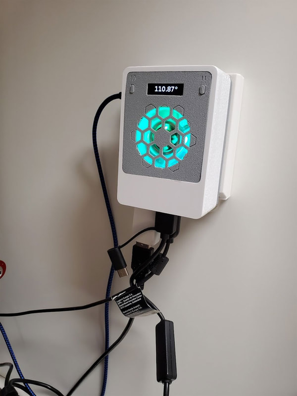
This is a build guide for the Button Module Remix for Sneaks' Modular Snap Together Raspberry Pi Case. This module includes two small 6x3.5x5mm momentary buttons. I am using one to safely shutdown the Pi, and the other will be a pause print button using the Physical Button plugin for Octoprint. I will include some info on how I set both these up. This module also utilizes the SSD1306 128x32 OLED display which is set up using the python script and setup guide that Sneaks provided here (but please try and link to that from his PrusaPrinters posting here, since that will be the most up to date link). The setup guide for the OLED is comprehensive, so please check that out to configure the OLED display.
A couple of caveats regarding this module first.
Bill of Materials (BOM)
A couple of caveats regarding this module first.
- The parts are very small, so please calibrate esteps and flow (for your filament), which will help with getting dimensionally accurate parts.
- Did I mention the parts are small? Some parts like the buttons need to have any elephant foot removed prior to using them, or they will stick and it will be no fun to take it all apart and get them out to clean them up.
- Please note the cautionary info in BOLD, since it may save you some headaches during assembly.
- If something does not work, check the wiring (especially the ground connections).
Bill of Materials (BOM)
- SSD1306 128x32 OLED display (you can get them with or without headers)
- 6x3.5x4mm Momentary Push Button Switches (I used the switches from this assortment) - edited this to remove a link for a larger pack of "6x3.5x5mm switches which I thought were the same (they look the same) but I cannot be sure since they list a slightly different size.
- 40x40x10mm (4010) 5V fan (I bought these with RGB LED's but any 4010 5V fan will work fine)
- 28 AWG Ribbon Cable is handy for this since the wires need to be as compact as possible. You may be able to salvage an old IDE or Floppy Drive cable which would probably also work if the wires are a low enough gauge. Ithe wires should be about 20cm long.
- Dupont connectors and a cripming tool, or you can splice and solder some dupont connectors onto the wires. You could also get some pre-crimped 20cm jumper wires like these and cut one end off. Whatever is used, make sure the wires are about 20cm long.
Step 1 - Test Fit the Buttons
This gets it's own step because it's important that the buttons move freely in their pockets. If they do not clean or trim the buttons (or scale then down and re-print them), and clean up any elephant foot on the holes they go into. Don't continue until the buttons move freely.
Step 2 - Connect the OLED
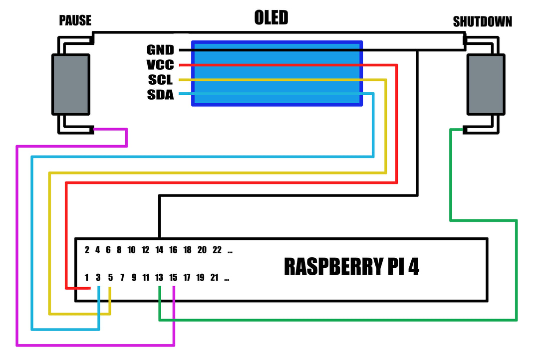
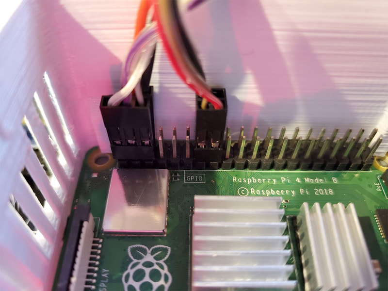
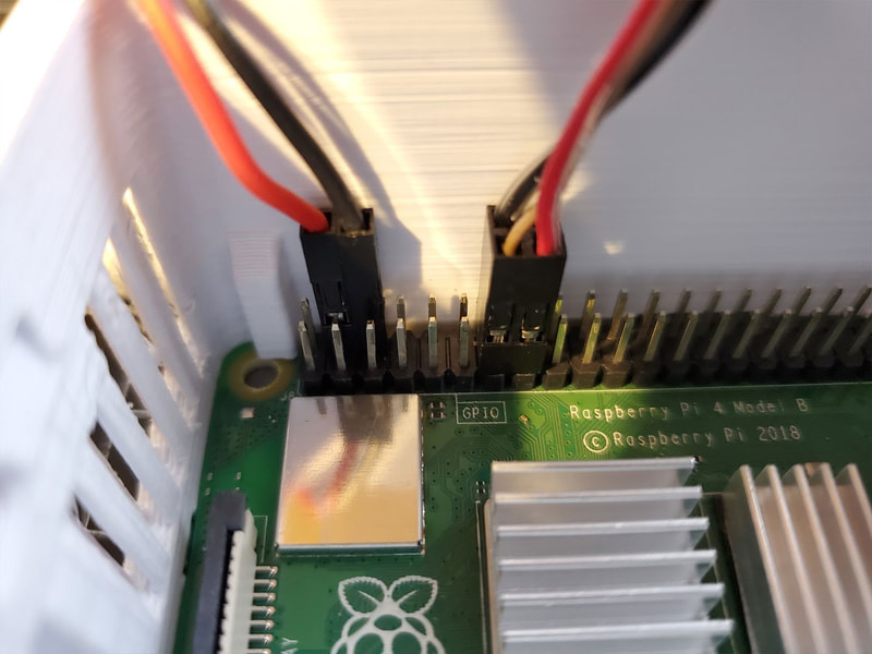
In order to try and minimize the rats nest of wiring, I configured mine as shown in the diagram below. It allows me to use one ground for the OLED and the switches. Keep in mind that the OLED uses 3.3v so be sure to connect it to the correct pin on the Pi (the Pi has both 3.3V and 5V power pins available). If in doubt, refer to the pinout for the Pi4.
Step 3 - Connect the switches
I hope you did not see the schematic and jump into installing the switches without reading this first. To install the switches, please do the following things before making any connections:
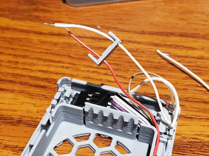
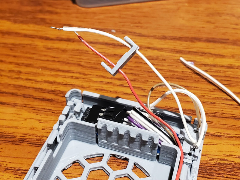
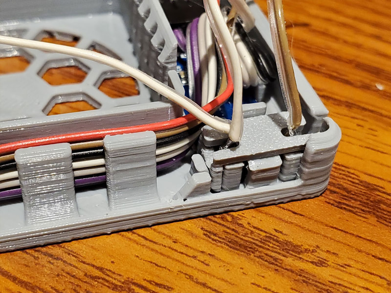
1. First, slide the clips onto the wires going to the switches. These only go on one way so it will help to verify that the thinner side of the clip is towards the center of the module.
1. First, slide the clips onto the wires going to the switches. These only go on one way so it will help to verify that the thinner side of the clip is towards the center of the module.
2. Install the buttons and make sure they move freely in the pockets (and don't get stuck). If they need to be trimmed or cleaned up it will save a lot of frustration later.
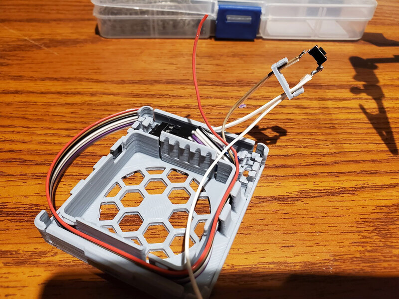
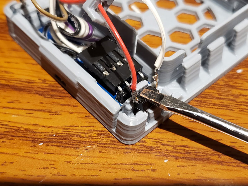
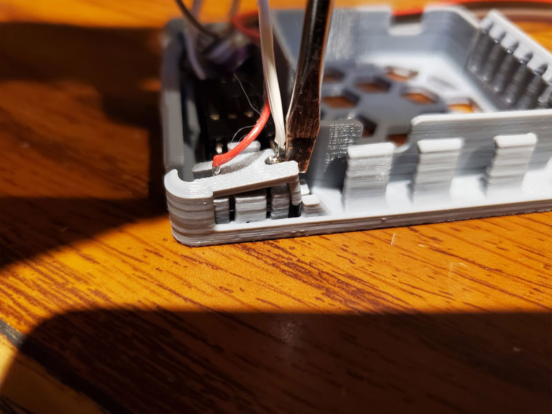
So now that's out of the way, just solder the wires to the buttons, and press them in place. I used the flat of a small regular screwdriver to set them in place. They are bit tough to press in, but they will go in. It can help to gently lever one of the clips a bit to get it started, but should not be necessary. Worst case, if you break a clip, the outside clip should hold the switch in place.
Once the switch in in place, make sure it operates OK, and then slide the pre-positioned outside clip down over it. Again I used a small regular screwdriver to press down on the ends of the clip to seat it.
Step 4 - Set Up the OLED and Test Before Moving On
Now really it would be better to test before installing the buttons in the prior step, but I have had a number of wring issues and none have been with the buttons since they are just soldered. Still if you wanna be safe maybe test before clipping the buttons in place. In any case test it out to make sure things work when placed in the module. I had a problem with the ground wires on mine, and then I found I had a either a defective (or blown) OLED so had to swap it out.
To test, there are 3 parts:
I honestly skipped testing the pause button since I had the pi away from the printer when I was setting it up, but to be through I will show how to test the pause button.
1. To test the OLED, please follow the setup guide that Sneaks provided here (but please try and link to that from his PrusaPrinters posting here, since that will be the most up to date link). The only thing I will mention is that if you run into an issue where the text is cropped on the bottom of the screen, just flip the screen 180° and then change the screen rotation to zero "0" in the oledDisplay.py (from the default "2"):
oled.rotation = 2 # 0:None // 1:90° // 2:180° // 3:270°
oled.rotation = 0 # 0:None // 1:90° // 2:180° // 3:270°
I had to do this on mine for some reason, but it was not the exact module that was recommended, but it looks very close (and mine has pin headers). In any case it's an easy fix.
Also, if you want to change the display from showing "MK3S ONLINE", you can change this line (it's right below where you can input your API):
cMessage = "MK3S ONLINE" # Message to show when octoprint is connected
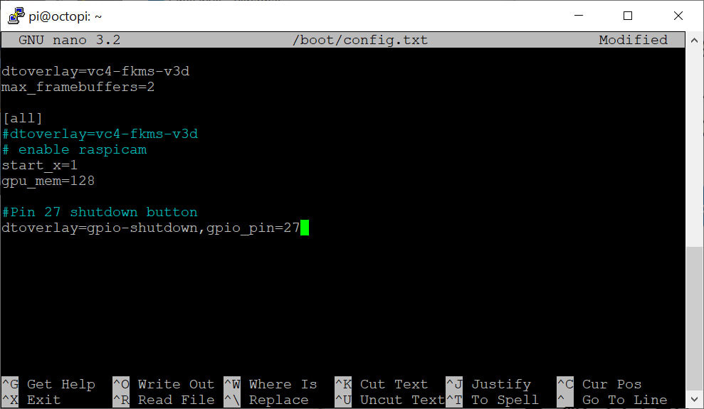
2. To test the Shutdown Button, you will need to log back into the Pi and add one line to /boot/config.txt (source):
dtoverlay=gpio-shutdown,gpio_pin=27
Note that "27" is the number of the GPIO pin that the switch is connected to, so in my case I used pin 27 which is the 7th pin down from the back of the Pi, on the row closest to the center of the Pi.
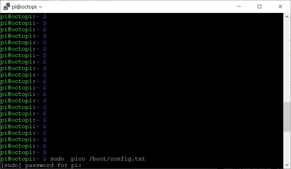
Use "sudo pico /boot/config.txt" to edit the file using pico, and place the statement at the bottom of the file. I also made a comment for it using "#" before the comment:
To test, there are 3 parts:
- Test the OLED
- Test the Shutdown Button
- Test the Pause Button
I honestly skipped testing the pause button since I had the pi away from the printer when I was setting it up, but to be through I will show how to test the pause button.
1. To test the OLED, please follow the setup guide that Sneaks provided here (but please try and link to that from his PrusaPrinters posting here, since that will be the most up to date link). The only thing I will mention is that if you run into an issue where the text is cropped on the bottom of the screen, just flip the screen 180° and then change the screen rotation to zero "0" in the oledDisplay.py (from the default "2"):
oled.rotation = 2 # 0:None // 1:90° // 2:180° // 3:270°
oled.rotation = 0 # 0:None // 1:90° // 2:180° // 3:270°
I had to do this on mine for some reason, but it was not the exact module that was recommended, but it looks very close (and mine has pin headers). In any case it's an easy fix.
Also, if you want to change the display from showing "MK3S ONLINE", you can change this line (it's right below where you can input your API):
cMessage = "MK3S ONLINE" # Message to show when octoprint is connected
2. To test the Shutdown Button, you will need to log back into the Pi and add one line to /boot/config.txt (source):
dtoverlay=gpio-shutdown,gpio_pin=27
Note that "27" is the number of the GPIO pin that the switch is connected to, so in my case I used pin 27 which is the 7th pin down from the back of the Pi, on the row closest to the center of the Pi.
Use "sudo pico /boot/config.txt" to edit the file using pico, and place the statement at the bottom of the file. I also made a comment for it using "#" before the comment:
Then reboot and try the button out. If you are connected to it, it should disconnect you. If it does not work, check the connections (especially the ground connection).
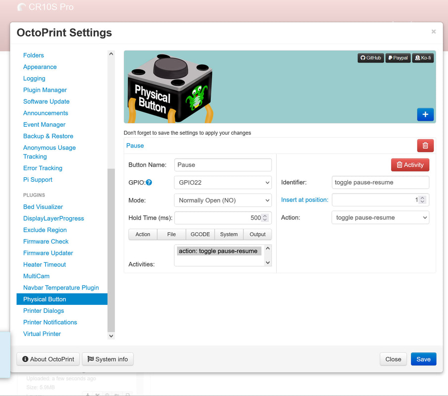
3. To test the Pause Button you will need to install the "Physical Button" plugin for Octoprint. Then configure it as follows (note that I am using GPIO22 so that is what I set here, if you use something else, substitute that value accordingly):
To test the Pause Button, you will need to start a print, then press the button to pause and resume the print. I also recommend configuring the Pause and Resume Scripts for Octoprint, which will add some intelligence to these functions.
Step 5 - Tuck In the Wires, Install the Fan and Thats It!
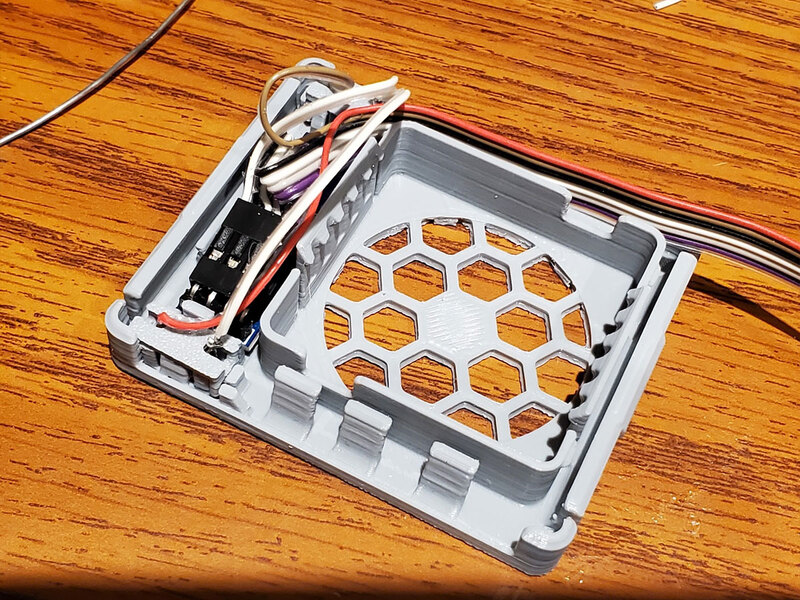
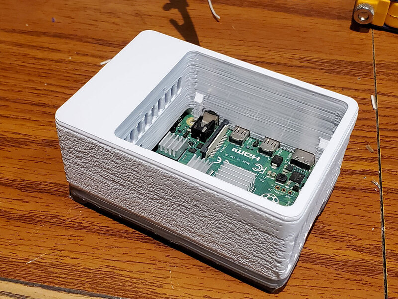
This is hardly a step but for completeness it is here. Tidy up the wires as best as possible. If it will fit, you can use the cover to hold the wires in place, but it's optional. The fan should be installed so the wires will reach the headers and there are two notches in the module for the wires to pass through. You can use the clips along the side to help with wire management as well.
Make the connections according to the OLED guide and the wire diagram, and then give everything one more test before closing it up.
Make the connections according to the OLED guide and the wire diagram, and then give everything one more test before closing it up.
Some Other Stuff...
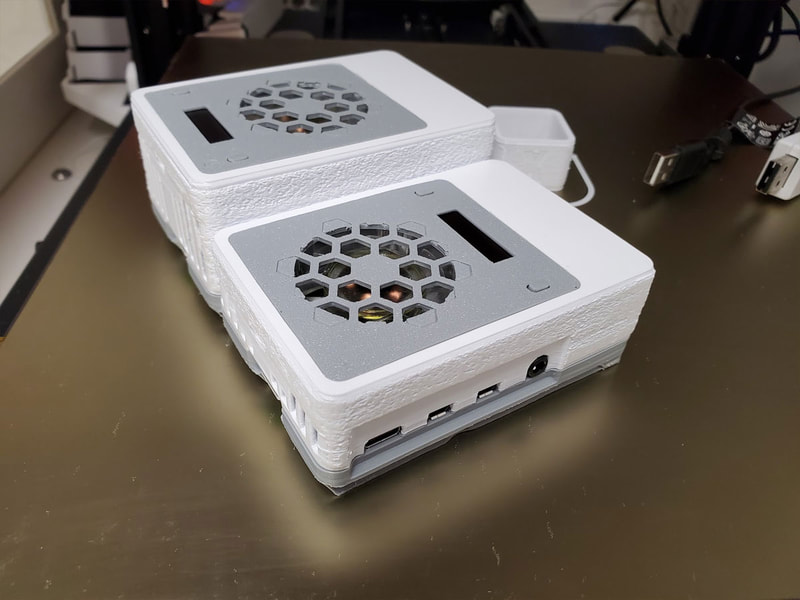
This design is a bit difficult to make, I admit. The small parts are dictated by the small space we have to work with here, but I hope it works out for you. I have built two cases and they both work well. My second case is a currently unposted remix of the top, which adds 12mm of extra height. This was needed to allow the switch module to be oriented with the display at the top since the switches will sit over the Pi's headers and there would not be enough room otherwise. The standard "deep" case can be used with this too though, but the OLED must be situated in the middle of the case with the fan above it. I like both these orientations so I can't see a drawback either way.
I will post this remix (of the switch module) to PrusaPrinters, and will include the STEP file so it will be easy to remix. If you like this, please post a make there, and if you have a problem, please leave a comment.
I will post this remix (of the switch module) to PrusaPrinters, and will include the STEP file so it will be easy to remix. If you like this, please post a make there, and if you have a problem, please leave a comment.
