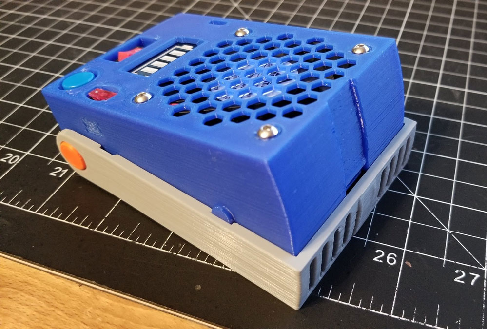
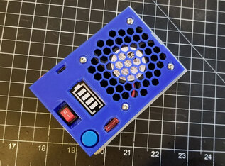
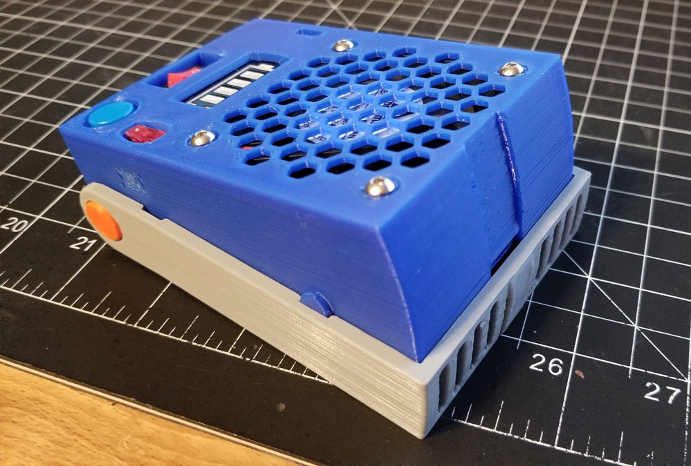
Solder Fume Extractor for the Stanley 014725R Organizer (version 2)
tSo the quick back story on this, is that I tried a similar design for a solder fume extractor about 2 years ago and it sucked, pardon the pun. The parts for this version can be found at the links below:
Solder Fume Extractor for a Stanley 014725R Organizer
https://www.thingiverse.com/thing:4816285
The major constraint for the design was that it has to fit inside a Stanley 014725R Organizer case, which I have already designed several other things for including a breadboard kit and a bench power supply (linked below):
Portable TS-80 Soldering Iron Battery Case (fits into the Stanley 014725R organizer)
https://www.thingiverse.com/thing:3389568
DSO112A Module for the Modular Breadboard Kit V2
https://www.thingiverse.com/thing:3638866
Component Tester Module for the Breadboard Kit V2
https://www.instructables.com/id/Component-Tester-Module-for-the-Breadboard-Kit-V2/
Modular Breadboard Kit V2 - small modules only (with STEP files)
https://www.thingiverse.com/thing:3416074
Modular Breadboard Kit V2 - small box module with lid (with STEP file)
https://www.thingiverse.com/thing:3714623
Modular Breadboard Kit V2 - small double box module with lid (with STEP file)
https://www.thingiverse.com/thing:3716154
DP20V2A Power Supply case for the Stanley 014725R Organizer
https://www.thingiverse.com/thing:3334709
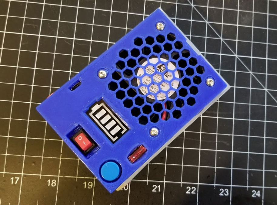
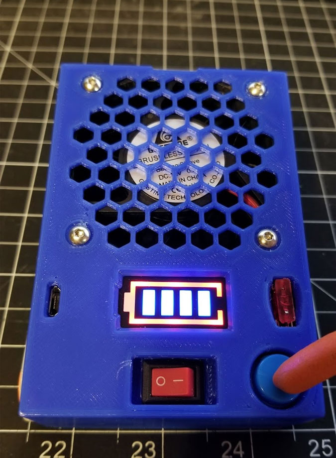
So 2 years later I finally decided to revisit the design and see if I could make it work using a bigger battery and a bigger fan. The constraint is the Stanley case it will go into, and so I was limited to a 60mm fan so I went with a 60x60x25mm fan like this one (nothing special, but I wanted one with a good amount of power). I would not recommend a noctura fan here since they are typically tuned to be quiet, but this design requires power and I didn't care about noise as much. If you do use one though please let me know how it works out. Since the initial attempt a new board design popped up using the same TP4056 and an adjustable boost converter built into one board. This was great since wiring the two separate boards together in the last design sucked, and took up way too much space inside the small volume for the electronics. Using the new board meant I would have more room for a bigger battery too. For the battery I used a 3.7V 523050 Lipo like this one here. In testing it was able to run the fan for about 1 hour before I turned it off. In subsequent usage I did notice that there is enough standby current draw from the TP4056 to draw the battery down a bit in storage (I didn't measure it but it maybe a quarter of the capacity every 6 weeks). The other components are a small LCD indicator for the battery, a push button, a fuse holder (and fuse), and a small 6A toggle switch. A Mini Micro JST PH 2.0mm female - or is it male (the convention on these connectors is very confusing since the pins are the opposite sex of the shell) in any case it's the mating connector to the one on the battery.
Bill of Materials Note - some of the links below are Amazon Affiliate Links. This means that, at zero cost to you, I will earn an affiliate commission if you click through the link and finalize a purchase. This will help to support this site and pay for more Stoopid Stuff.
I tried to link to the actual items I have bought, or if they are not available, similar items which I would buy based on value, but they are by no means the only options that will work. Regarding the screws in particular, I linked to some assortments I have bought or would buy, and in this case it may be best to look for something with M2 and M3 screws, but it will be difficult to find an assortment which has them all (for example there are M3x30mm screws needed). I's suggest maybe getting a good assortment of the M3 screws for the M2, you may be able to use a slightly longer M2x12mm with some washers. There may be an assortment would work more generally like this, or you can get the exact screws from a local Ace Hardware, Zoro.com or BoltDepot. I tend to buy assortments since I like to collect them :D
The parts were sourced from Amazon and Ebay and the parts list with the name of the items as I found them is below:
That is a big BOM :D, but nothing I can do about it unfortunately. Many of the parts I had around, with some I had to buy, so my total cost was lower. If you plan on making the other breadboard kit stuff though, the tactile and toggle switches are used for that project, along with the M3 inserts.
Solder Fume Extractor for a Stanley 014725R Organizer
https://www.thingiverse.com/thing:4816285
The major constraint for the design was that it has to fit inside a Stanley 014725R Organizer case, which I have already designed several other things for including a breadboard kit and a bench power supply (linked below):
Portable TS-80 Soldering Iron Battery Case (fits into the Stanley 014725R organizer)
https://www.thingiverse.com/thing:3389568
DSO112A Module for the Modular Breadboard Kit V2
https://www.thingiverse.com/thing:3638866
Component Tester Module for the Breadboard Kit V2
https://www.instructables.com/id/Component-Tester-Module-for-the-Breadboard-Kit-V2/
Modular Breadboard Kit V2 - small modules only (with STEP files)
https://www.thingiverse.com/thing:3416074
Modular Breadboard Kit V2 - small box module with lid (with STEP file)
https://www.thingiverse.com/thing:3714623
Modular Breadboard Kit V2 - small double box module with lid (with STEP file)
https://www.thingiverse.com/thing:3716154
DP20V2A Power Supply case for the Stanley 014725R Organizer
https://www.thingiverse.com/thing:3334709
So 2 years later I finally decided to revisit the design and see if I could make it work using a bigger battery and a bigger fan. The constraint is the Stanley case it will go into, and so I was limited to a 60mm fan so I went with a 60x60x25mm fan like this one (nothing special, but I wanted one with a good amount of power). I would not recommend a noctura fan here since they are typically tuned to be quiet, but this design requires power and I didn't care about noise as much. If you do use one though please let me know how it works out. Since the initial attempt a new board design popped up using the same TP4056 and an adjustable boost converter built into one board. This was great since wiring the two separate boards together in the last design sucked, and took up way too much space inside the small volume for the electronics. Using the new board meant I would have more room for a bigger battery too. For the battery I used a 3.7V 523050 Lipo like this one here. In testing it was able to run the fan for about 1 hour before I turned it off. In subsequent usage I did notice that there is enough standby current draw from the TP4056 to draw the battery down a bit in storage (I didn't measure it but it maybe a quarter of the capacity every 6 weeks). The other components are a small LCD indicator for the battery, a push button, a fuse holder (and fuse), and a small 6A toggle switch. A Mini Micro JST PH 2.0mm female - or is it male (the convention on these connectors is very confusing since the pins are the opposite sex of the shell) in any case it's the mating connector to the one on the battery.
Bill of Materials Note - some of the links below are Amazon Affiliate Links. This means that, at zero cost to you, I will earn an affiliate commission if you click through the link and finalize a purchase. This will help to support this site and pay for more Stoopid Stuff.
I tried to link to the actual items I have bought, or if they are not available, similar items which I would buy based on value, but they are by no means the only options that will work. Regarding the screws in particular, I linked to some assortments I have bought or would buy, and in this case it may be best to look for something with M2 and M3 screws, but it will be difficult to find an assortment which has them all (for example there are M3x30mm screws needed). I's suggest maybe getting a good assortment of the M3 screws for the M2, you may be able to use a slightly longer M2x12mm with some washers. There may be an assortment would work more generally like this, or you can get the exact screws from a local Ace Hardware, Zoro.com or BoltDepot. I tend to buy assortments since I like to collect them :D
The parts were sourced from Amazon and Ebay and the parts list with the name of the items as I found them is below:
- 60x60x25mm Fan - I used one like this (amazon item B00Q7XB5AS)
- Lithium Li-ion Battery Charger Module Boost 3.7V to 5V 9V 12V Adjustable DC-DC Step Up Boost Module TP4056
- 3.7V 1000mAh 523050 Lipo Battery with JST connector (mine has a Mini Micro JST PH 2.0 connector)
- a compatible connector for the battery with at least a 150mm wire tale (or make your own) - mine were Mini Micro JST PH 2.0mm
- 1S Lithium Battery Capacity Indicator - I used one like this (note the version is "1S" or one cell): https://www.ebay.com/itm/1S-2S-3S-4S-4-2-8-4-12-6-16-8V-Lithium-Battery-Capacity-Indicator-Power-Tester-F/253727781563
- A PCB Panel Mount Small Medium Universal Car Fuse Holder (with a compatible ATM micro mini automotive fuse) - these seem hard to find in low values, but I am using a 5A and have some 3A on order. I bought my fuse holders on Ebay, but that link no longer works, however I found them on Amazon here. When buying fuses though, get some good quality name brand fuses if you want them to work.
- M3 x 4mm x 4.3mm brass inserts (5 needed). I used these which are M3 x 4mm x 4mm and melted them in, but any inserts that will fit a 4.3x6mm hole will work.
- Carbon filters (trying these), but whichever are used, they need to be thin enough to fit the compartment on this. For the ones shown below, I carefully sliced about 2-3mm from the filter, to thin it, which also improved the airflow considerably. The filters linked below are for garbage can deodorizers.
- 3A/250V 6A/250V switch from this assortment (using the smaller ones). UPDATE 12/12/2021 - I found a 3 position mini toggle which I plan to try, the benefit of using it may be that I can completely disconnect the battery from the charging circuit (which will help with battery drain when it is stored). The downside is that the KCD11 3A/250V 3 Pin SPDT ON-OFF-ON 3 Position Snap Rocker Switch is hard to find and I will have to wait several weeks to get them and I will have to wait till then to test it out.
- 12x12x7.3 mm Tactile Push Button Momentary Switch with Cap
- M3x20mm flat head screw (1)
- M3x30mm round head screw (4)
- M2x10mm screw and washers (2 of each)
That is a big BOM :D, but nothing I can do about it unfortunately. Many of the parts I had around, with some I had to buy, so my total cost was lower. If you plan on making the other breadboard kit stuff though, the tactile and toggle switches are used for that project, along with the M3 inserts.
Building it
Not gonna cover printing, but to build it, I documented the steps I took below. The following tools were required to build it:
One word of caution is that I am not an electronics expert, just a random dude on the Internets. I did the best I could here, with the design and schematic, but if you see anything that could be improved, please let me know. This project requires working with soldering irons, Lipo batteries and lighters, so making this is at your own risk. Please pay special attention to verify the polarity of the battery and any connectors used before connecting them up (or trusting the color coding of the wires). A shorted Lipo battery is a dangerous and a fire risk.
- Soldering iron and solder
- Wire cutter and wire stripper
- Lighter or candle (for heating the M3 inserts)
- Screwdriver for M3 hardware
- Pliers
- Electrical or Kapton tape
- Heatshrink
- Extra wire (I would use at least 22 gauge)
- All the 3D printed parts (cleaned of support material).
One word of caution is that I am not an electronics expert, just a random dude on the Internets. I did the best I could here, with the design and schematic, but if you see anything that could be improved, please let me know. This project requires working with soldering irons, Lipo batteries and lighters, so making this is at your own risk. Please pay special attention to verify the polarity of the battery and any connectors used before connecting them up (or trusting the color coding of the wires). A shorted Lipo battery is a dangerous and a fire risk.
Step 1 - test the board with the fan and adjust the voltage.
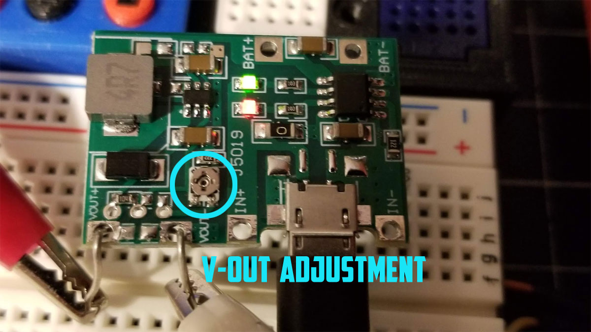
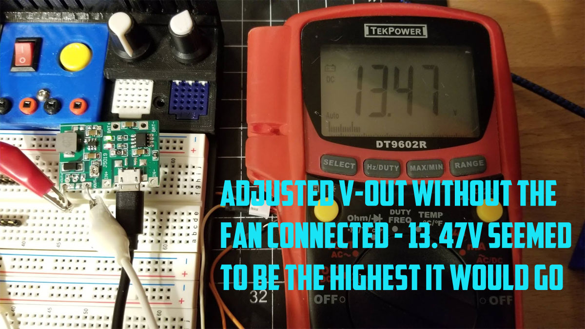
First it is required to test the board and tune the output voltage from the board. To do that I set up the components on a breadboard to test them and then adjusted the small potientiometer on the USB board to set the output voltage to the fan. This was a bit tricky to get set but it has to be done or the board will not power the fan.
Now is a good time to verify that the polarity of the battery connector matches up with the wire colors on the female JST connector (I have read some reviews on Amazon saying the polarity of the battery connector was reversed on some batteries - though I did not have that problem). A multimeter set to DC volts can be used to confirm the polarity.
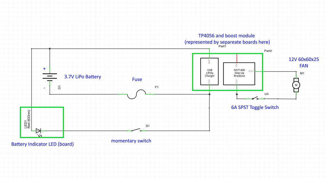
There is a post here showing how I set up and adjusted my board and fan. Below is the schematic I used. Initially I had a flyback diode over the fan output but removed it when I confirmed that my brushless fan does not require one (confirmed using a cheap scope). Since any fan for a PC will be brushless these days I don't think a flyback diode is needed and I did not use it in the final design (though a diode is still pictured in the link above which describes how I set up and tested the USB charge/boost board).
UPDATE 12/13/2021 - After using this for a while, I found that the battery will drain due to simply being connected to the charging circuit. It is not a big deal if it is stored for a few days between uses, but when I put it on a shelf for 2 months, it is annoying since I will need to recharge it before using it. To hopefully fix that, I ordered a "KCD11 3A/250V 3 Pin SPDT ON-OFF-ON 3 Position Snap Rocker Switch" from Ebay which will be here in Jan 2022 sometime. With a 3 position rocker, and s Schottky diode, I will see if I can set it up so that position one will be for charging only, center (position two) will be battery disconnected, and position three will be fan on (and also charging). I will post an updated schematic for the 3 position (on-off-on) switch, once I test it, since I am not sure if there will be a problem with power due to the voltage drop over the diode.
Step 2 - Install the fan
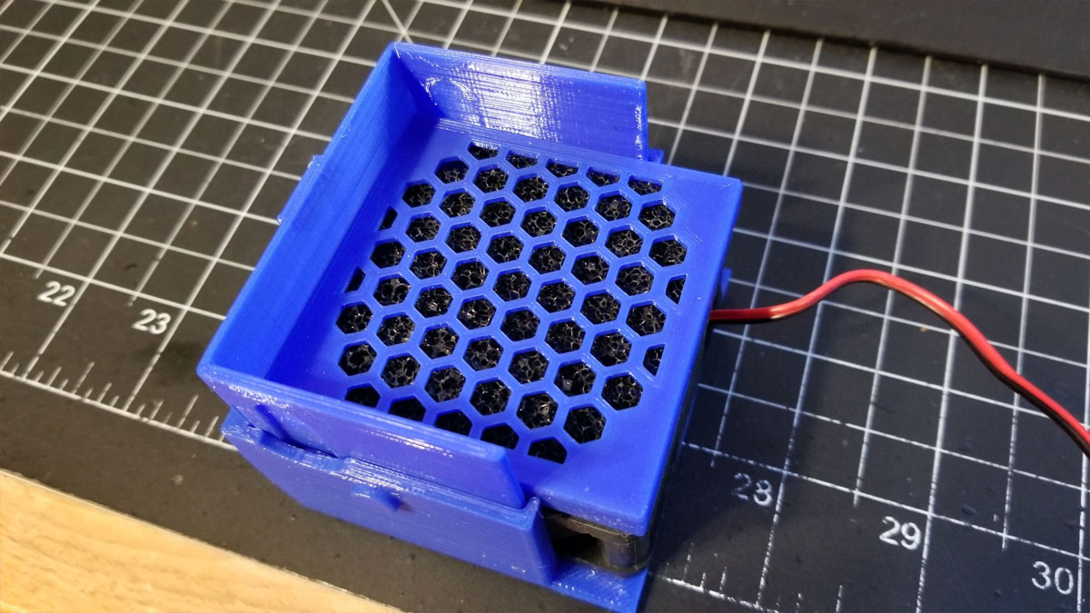
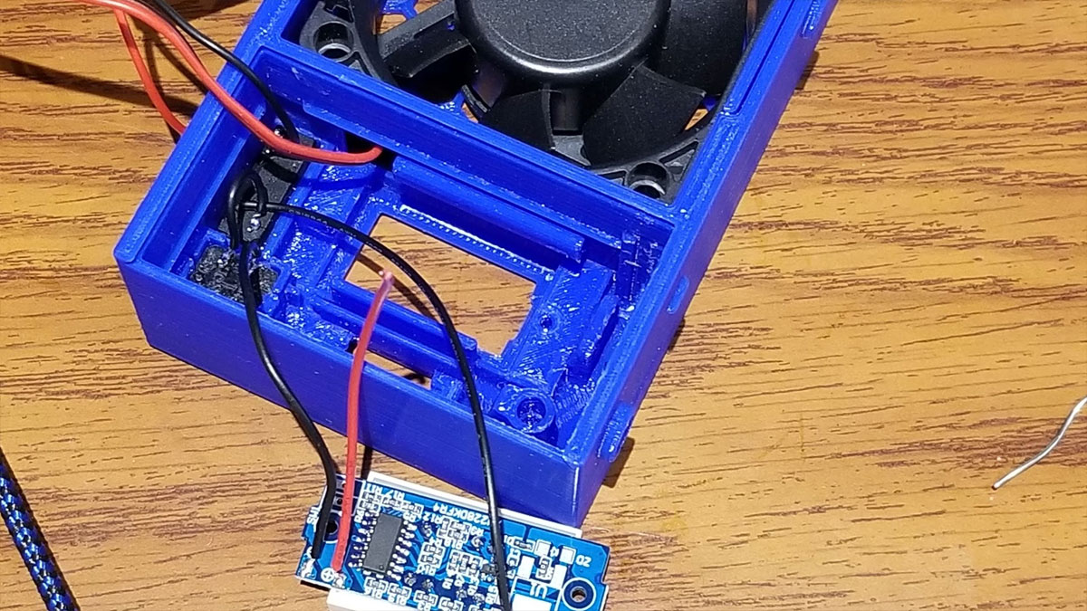
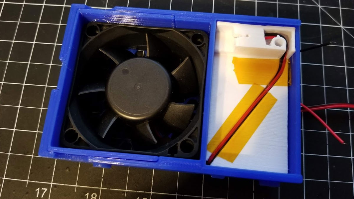
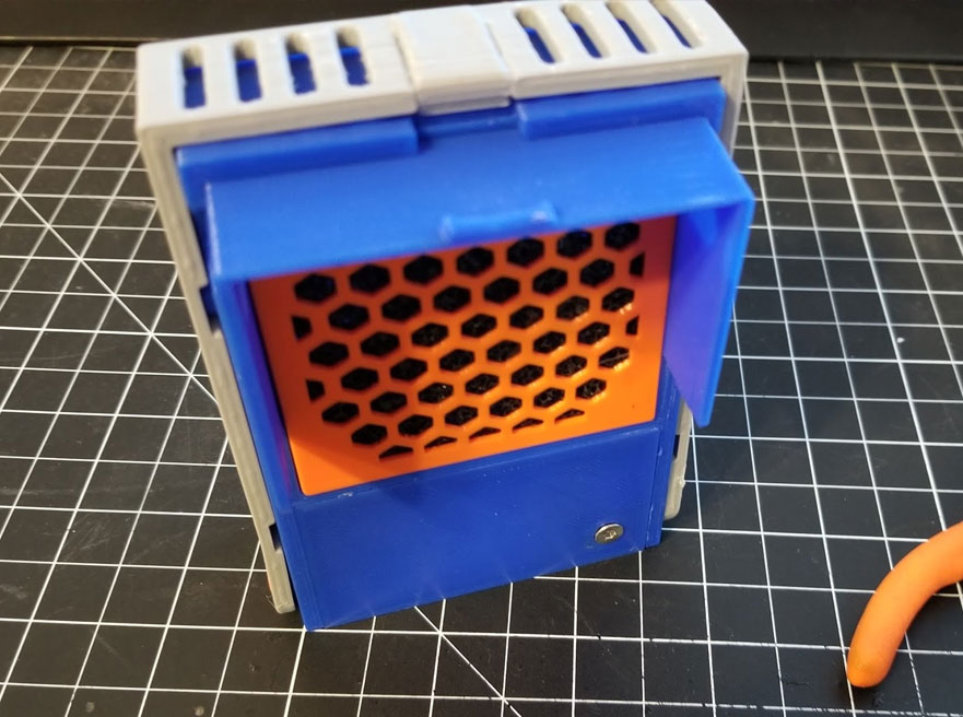
Not gonna lie, getting the fan in took some time and care, but it did go in. To install it, the sliding fan shroud was installed first (it slides out and ducts the air into the fan when it's all together). I also shaved just a tiny bit off the corner of the fan so the wire would have just a bit more clearance to go around it (this may not have been necessary but I think it helped with my fan). Then I made sure to orient the fan so it would blow in the correct direction, most of them blow towards the side with the label or have a mark on the side showing the direction. In any case it needs to blow towards the side of the case with the buttons. Then I routed the wire through the hole between the fan pocket and the electronics area. Then it was a bit of work'in and curs'in to get the fan installed without damaging the wire. The key was not to force it. I didn't get a good pic of this step, but the pics below show the shroud (when I was testing it, but it's the same thing), and the 2nd pic shows how the wire goes through the hole between the fan pocket and the electronics area.
Step 3 - Assemble the battery tray
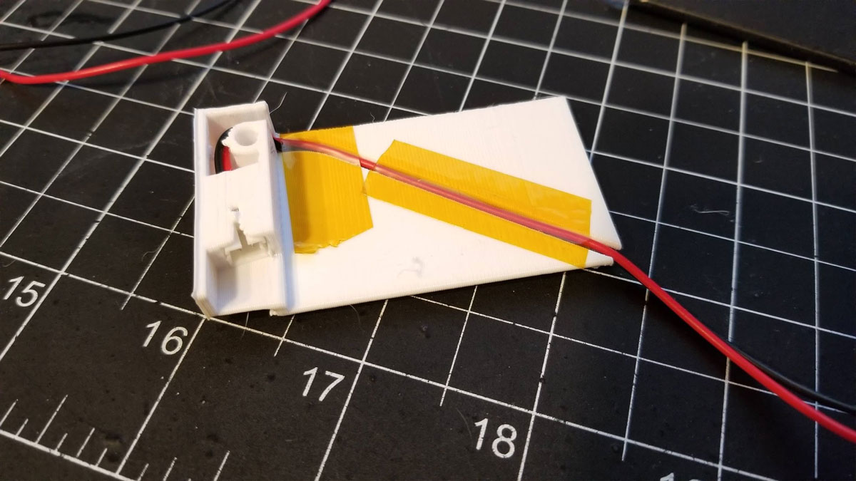
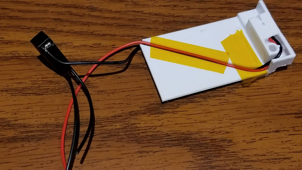
The battery tray is designed for a Mini Micro JST PH 2.0mm plug with a female shell and male pins. These are hard to find unfortunately but I was able to get some on ebay. The connector with wires was threaded through the hole in the battery tray and the wires were routed in the cable track and held in with tape.
Step 4 - Begin the assembly of the electronics
This build has lots of small parts and is a bit difficult, there may be a better way to put it together, but this is how I did it. I first tinned all the contacts on the switches, fuse holder and boards that need it.
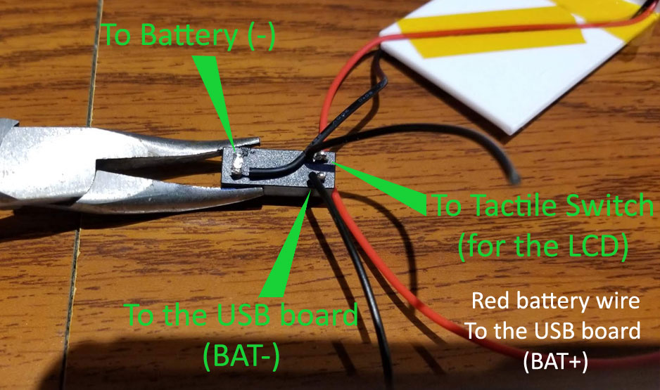
Next I cut the black wire from the battery holder a couple inches from the edge of the holder and soldered that one leg of the fuse holder. I folded the other leg on the holder next to it down to get it out of the way. I added two back wires to the other side of the fuse holder, one short (goes to the momentary switch) and one long (goes to the USB board).
Next I cut the black wire from the battery holder a couple inches from the edge of the holder and soldered that one leg of the fuse holder. I folded the other leg on the holder next to it down to get it out of the way. I added two back wires to the other side of the fuse holder, one short (goes to the momentary switch) and one long (goes to the USB board).
Step 5 - Install the LCD voltmeter and tactile button
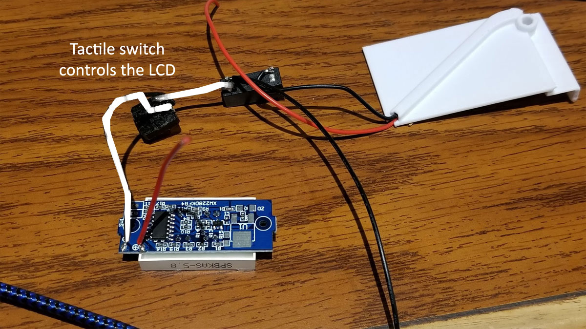
So next up is I had to take the short wire that was connected to the output side of the fuse holder, and connect it to one leg of the tactile switch. Note that the switch is wired internally so that the legs on both sides are different poles of the switch. I bent the pins on the switch down and clipped the pins off on the other side. These were tinned and then I just soldered the short black wire from the fuse holder to one leg, and then took another loner wire (a bit more than 2") and connected that to the LCD volt meter.
To gauge the wire lengths, I previously dry fit the LCD voltmeter, to verify how it will sit. Note that the orientation of the cutout in the case is designed to match the battery design on the LCD (so it only goes one way). Also note that some versions of these LCD voltmeters have the pins in the diagonally opposite corner than the one shown below, so it is really important to dry fit to get a good idea of how long the wires should be. There are several cable management wire holders that can also be used to keep the wire clutter down.
I then soldered a red wire to the "+" pad on the LCD voltmeter, this will later be twisted with the battery "+" and connected to the "BAT+" pad/hole on the USB board.
The 2nd pic below shows the fuse holder was at this point glued into the case using superglue, and the tactile switch was snapped in as well. Next up will be the LCD voltmeter. If I did this again I would add some glue to the holes before setting the LCD voltmeter in place, though I didn't and it seems solid with the M2 screws used to mount it.
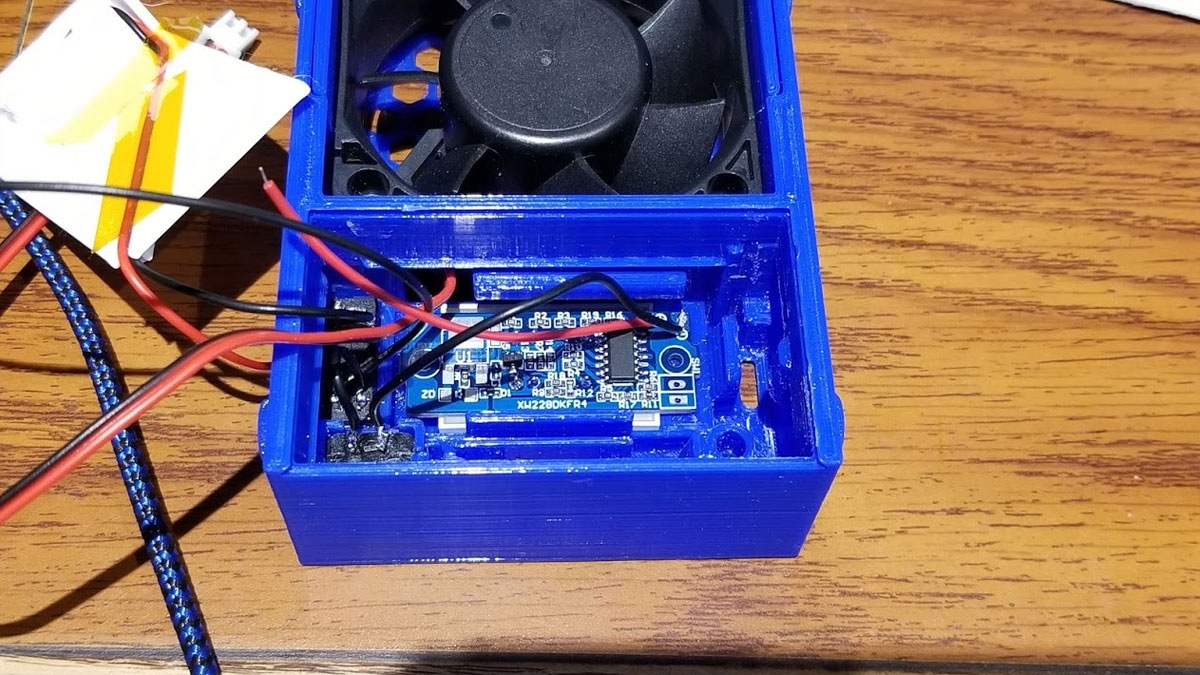
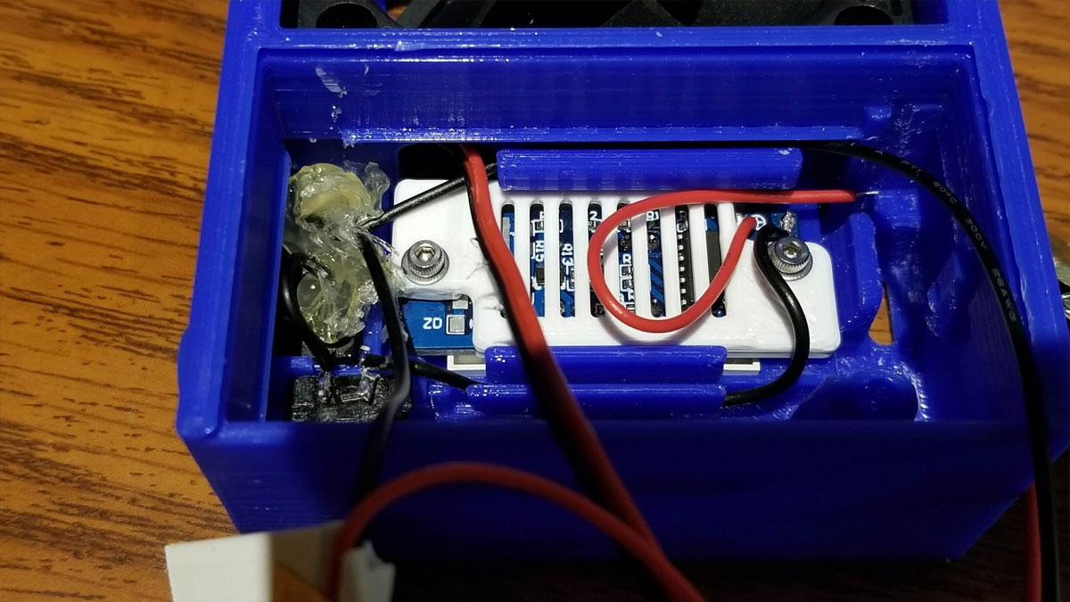
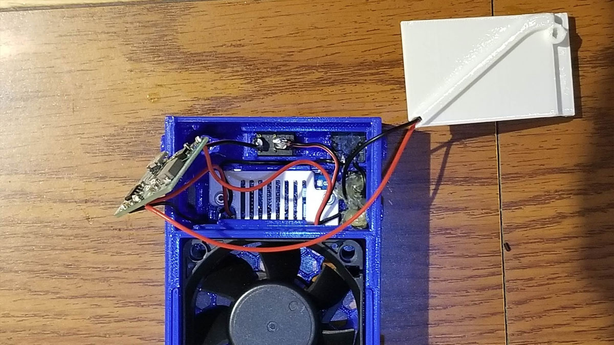
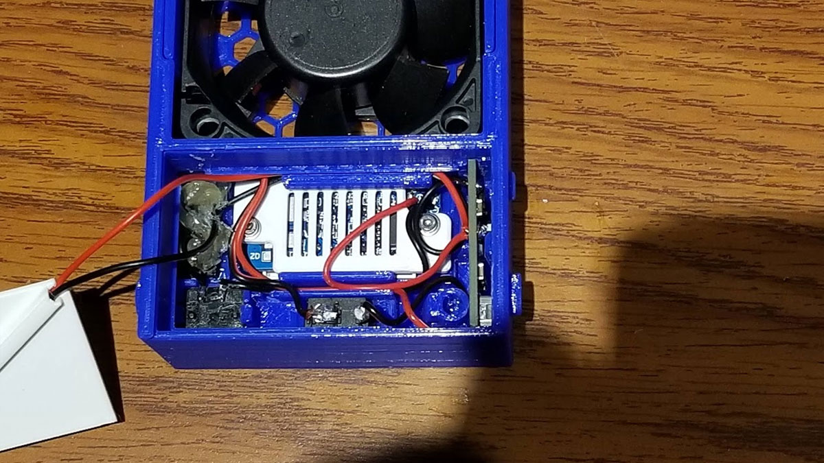
Next, I installed the LCD voltmeter, and the button for it, making sure it was in the correct orientation for the window. The voltmeter goes in first at a bit of an angle and then drops in. Next the cover goes over the LCD voltmeter. The cover has cutouts for both types of LCD voltmeters I have found, but it only goes on one way. A couple of M2x10mm screws with washers hold the LCD voltmeter and cover in place. Some glue on the screws is probably something that would have helped but I forgot. I later added some superglue to the button as well to better hold it in place. Finally I put some hot glue over the fuse holder and wires to act as a bit of strain relief on those wires (that's the big booger looking mess in the 4th pic below). There is an unconnected red wire from the LCD voltmeter, and the battery ground wire (from the fuse holder) which is routed through the wire channel above the LCD in the right pic below. The wire running from top to bottom and out of the case is the fan wire which is not yet touched (also in the right pic below).
Step 6 - Install the USB Charing / Boost regulator board
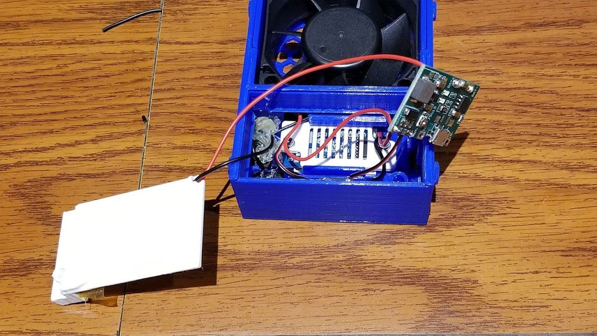
Just noting again - before installing the USB charging and boost regulator board, the output voltage must be adjusted using the onboard potientometer as described here (note the diode using that example was not necessary but the diode legs did make it handy to mount the board for testing). Since my board was tested and set to the correct output voltage for the fan, I soldered the wires to the USB charging and boost board (will call it the "USB board from this point). The red wire from the battery (+) was twisted with the red (+) wire from the LCD voltmeter and those were soldered together first. Then they were connected to the "BAT+" hole on the USB board. The black wire from the fuse holder (which I ran through the wire management channel) was connected to the "BAT-" hole on the USB board.
The board was not installed in it's final location yet, since the fan wires still needed to be connected.
The board was not installed in it's final location yet, since the fan wires still needed to be connected.
Step 7 - Connect the fan and toggle switch
The fan connects to the "VOUT+" and "VOUT-" connections on the board, but there is a switch which controls it (I placed it on the negative side). I soldered a short black wire to the "VOUT-" connection on the USB board first, and then the red wire from the fan was cut to length and soldered to the "VOUT+" connection on the USB board.
Then I tinned the posts on the 6A toggle switch and snapped it in place. I bent the posts down a bit to make them easier to connect up the wires.
The short black wire (connected to "VOUT-") was soldered to one side of the toggle switch, and the other side was connected to the black wire from the fan (using heat shrink to insulate the posts).
Now all the connections were made, and it was tested with the battery. Once I confirmed the switches worked, I pushed the USB board into place. It is a friction fit and the USB port needs to line up with the hole in the front of the case. I previously cleared some supports from this area which would have blocked it from going in.
The electronics part was done at this point.
Step 8 - Final assembly of the electronics and battery compartment
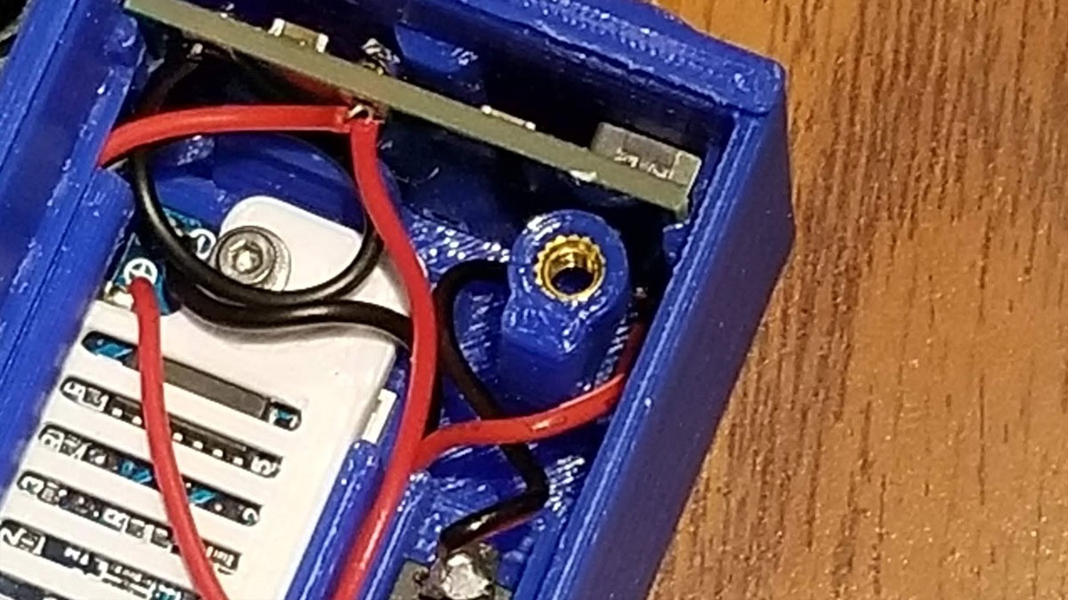
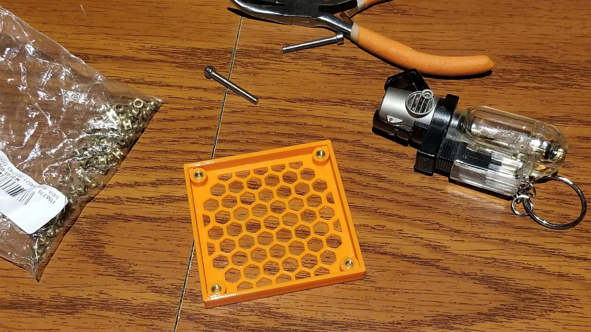
To complete the case, I had to install the M3 inserts. To do this, I used a jet butane lighter (any lighter or candle will do though). I threaded the M3 insert onto the end of a long M3 screw (the 30mm screws used to hold the fan work great), and held the screw with a pliers while I heated it up for several seconds using the lighter. The brass inserts just need to get hot enough to melt the plastic so about 3 seconds was usually enough time in the flame. Once it was heated up, I pressed it into the hole in the post next to the USB board in the 2nd pic above.
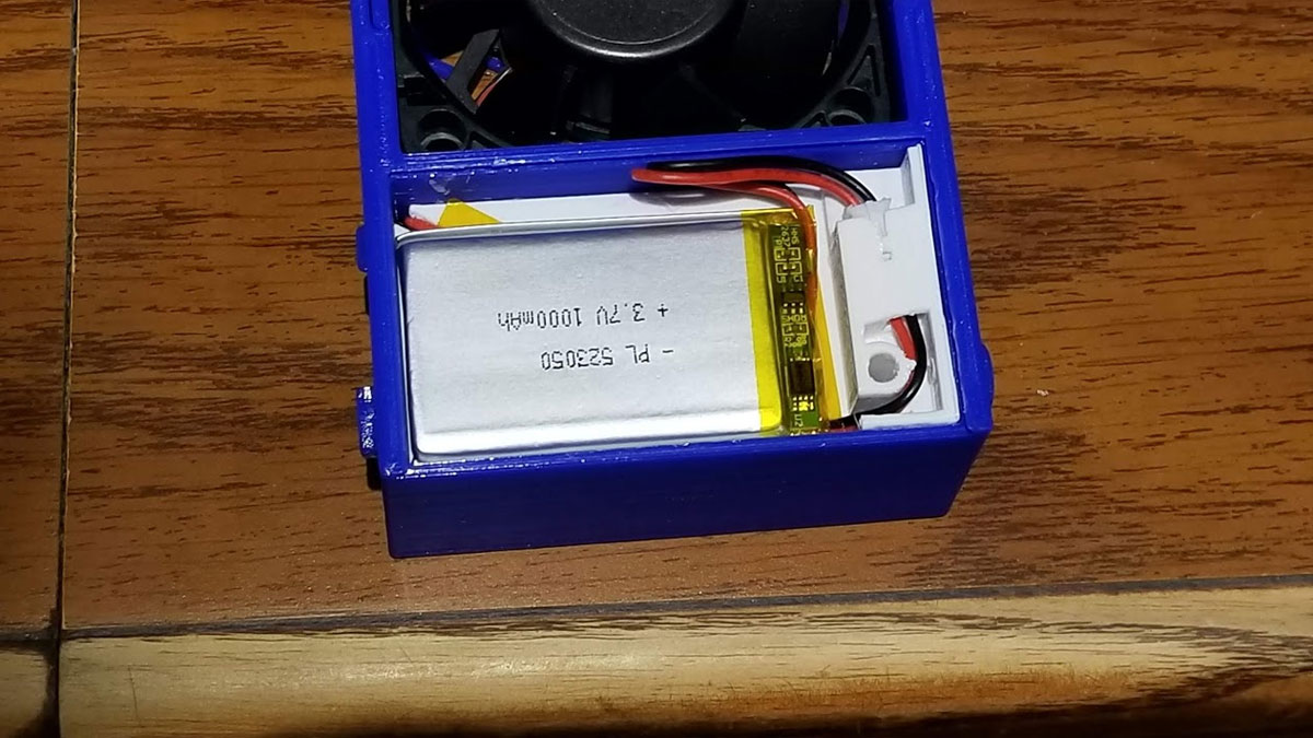
Then the battery tray was installed, taking note of the cable routing. The tray will sit flush with the front lip of the case (which will allow the cover to slide on). Then the battery was installed in the tray and the battery cable was tucked down. Next the cover was slid on and secured with an M3x20mm flat head screw.
Then the battery tray was installed, taking note of the cable routing. The tray will sit flush with the front lip of the case (which will allow the cover to slide on). Then the battery was installed in the tray and the battery cable was tucked down. Next the cover was slid on and secured with an M3x20mm flat head screw.
Step 9 - Install the fan cover and screws
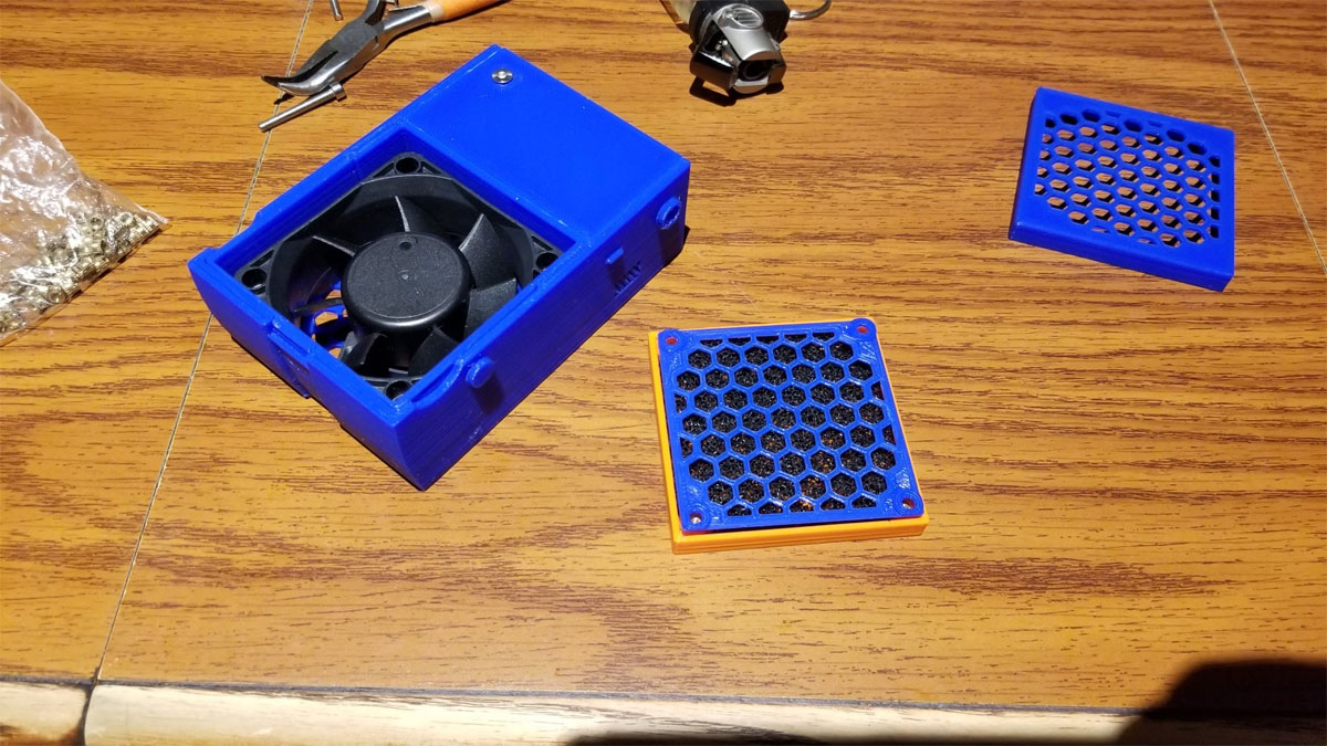
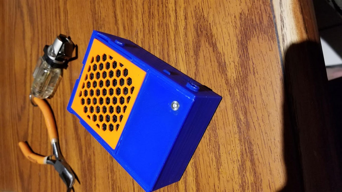
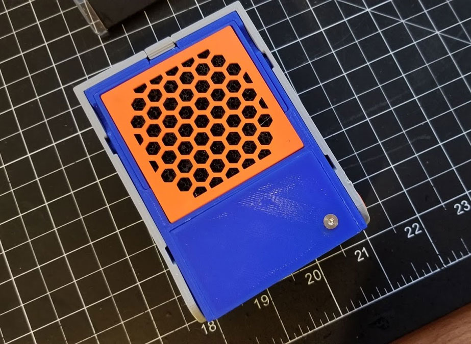
This part is simple, just install the M3 inserts in the fan cover, place the carbon filter in the cover (cut it to size), and then add the filter separator (printed in blue in the above pic). Then use the four M3x30mm screws to install the fan cover and secure the fan in place.
Step 10 - Install the arm
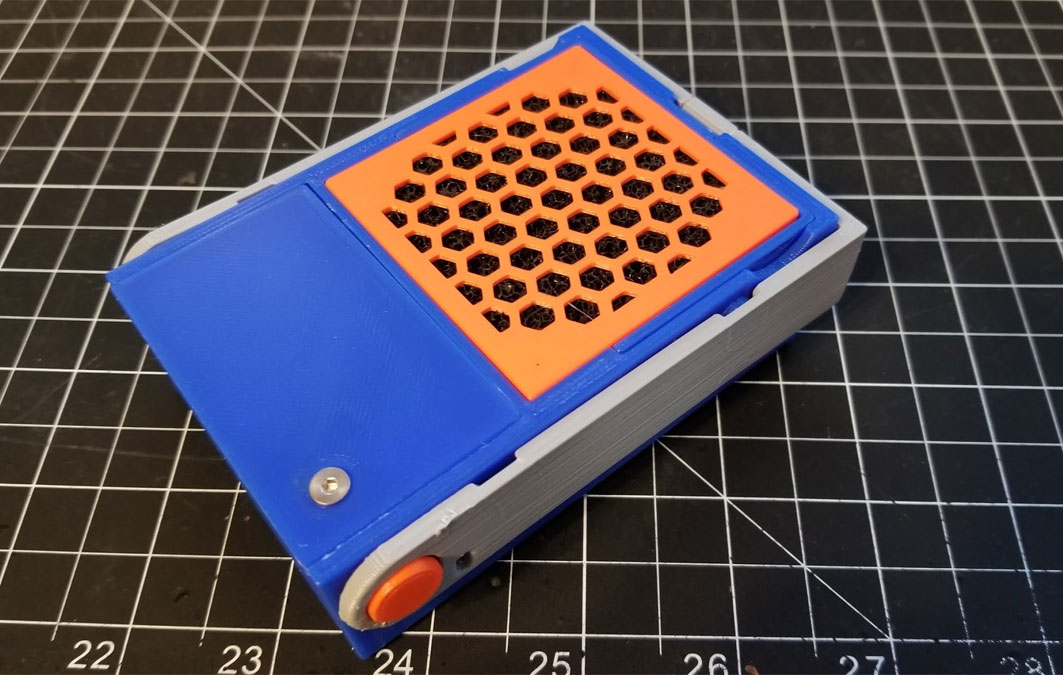
The arm simply snaps over the lugs on the side. There is a hole in the arm to view the status of the lights and the orientation is pretty simple. Once the arm was in position, the caps were pressed into place (with some glue) to hold the arm in place. And that was it. The arm swings around so the fume extractor can be used when working close to the work surface, it sort'a focuses the suction of the fan. It can also be used standing upright, and in that orientation the arm can be folded to store and the fan duct can be slid out to help focus the suction of the fan.
Some Other Stuff
So far this has been a worthwhile project and I use it a lot - however I did not use it for several months, and it was in storage. When I retrieved it, I found that the battery was dead, and it did not seem to take a charge. I thought perhaps that the battery had over discharged, however when I checked the voltage of the cell after charging for several hours I found that it was about 3.7 volts. After reconnecting it, it seemed fine and I continued to charge it till full. I then tested it by running it for 20 minutes, and it probably could have gone more than twice that time since it was still going strong with three bars on the battery indicator. So if it is in storage for a while, I'd probably reseat the battery connector if it appears that it's not charging.
