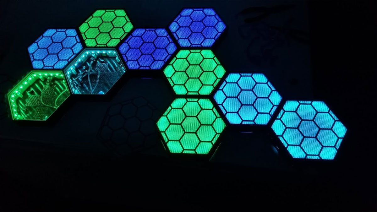
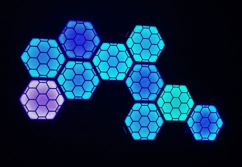
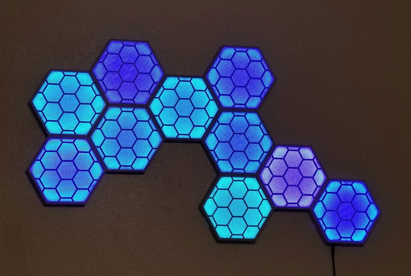
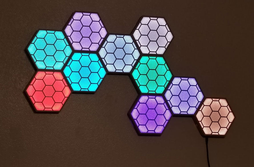
How I assembled the HexLED PANELS
I removed the earlier design right after posting it to make some improvements to some of the components I initially used for this project. The updated design is done and although I am happy with it, I have to make it known that I could not find an "appropriate" DC switch to use with this. Most small switches seem to be rated for AC current, which I believe will have a higher current rating than an equivalent DC switch, though I am not a switch expert (I'm just a hobbyist when it comes to electronics). As I am using a 4A 5V DC power supply, and the switch I am using is rated for "AC 250V/6A 125V/10A" I think it should work OK, but again I am not an expert on this, so please use your own judgement and decide for yourself what is appropriate. I based the choice of switch I am using on the fact that I will be pushing a much lower current at lower voltage (upto 4A at 5V DC) though the switch (in DC) than what the switch is rated for in AC (10A at 125 VAC) - but again the ratings are not the same or comparable between AC and DC switches. That said, I would recommend that anyone making this consider the components being used, and make their own educated choices on the requirements and types of components to use used, and take responsibility for those choices. If not sure, do the research to find out. In other words, THIS IS A MAKE IT AT YOUR OWN RISK PROJECT.
I will provide links to the parts I used, however you should decide if you want to use the same parts or not, if you plan to make this or something similar. The STEP files are available on Thingiverse for those who want to modify and remix this to use other components. If you have some better components in mind please let me know.
This webpage is a build log, describing how I assembled my HexLED Panels. These panels were inspired by NerdForge's HexaLeaf LED Panels, and they use his code, and a similar electronics design, with the primary difference being these can be fully printed (including the screens) and have a few additional features. His code works very well, so big thanks to NerdForge for sharing his project! I suggest that if you plan on making this, and using his code, please check out his YouTube channel and consider supporting his projects on Patreon (https://www.patreon.com/nerdforge). I'm sharing the design for my version of the physical parts on Thingiverse and possibly Cults3D, as well as the STEP files, so others can hopefully improve the design.
Most of the assembly is straightforward but there are a few things which made me go back and re-work it (like noticing the LEDs were a bit less bright towards the end of the string, causing me to add some power injection points). Due to the tight fit on some parts, before I printed anything I calibrated the flow on each machine I was using to print, for each filament type being used (see here and here). I also measured the horizontal expansion for each filament, on each machine, to get the parts as closely fitting and to spec as possible. I use a simple 5x25x25mm test cube with a 10x10mm hole in the center to do this, using a method similar to what is described on the mattshub link, but any simple test cube will work. I can't say if this was necessary, but I can say that everything fit.
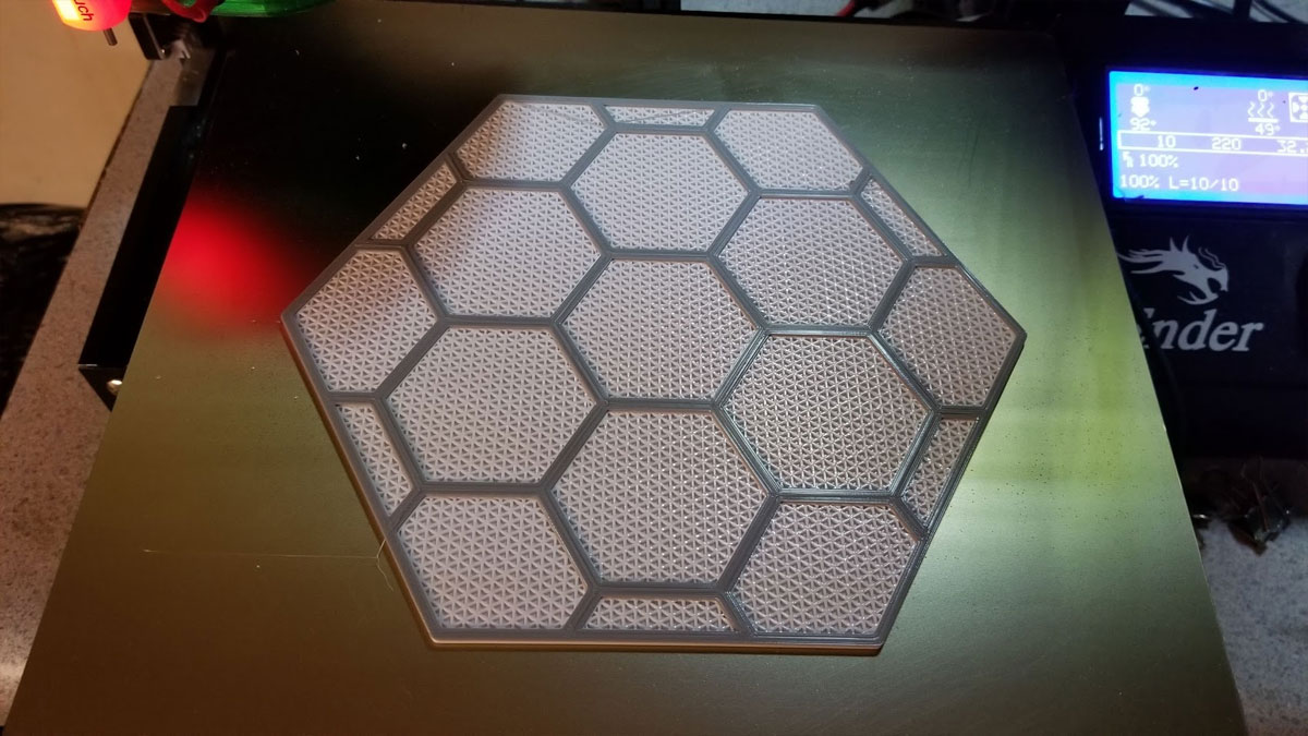
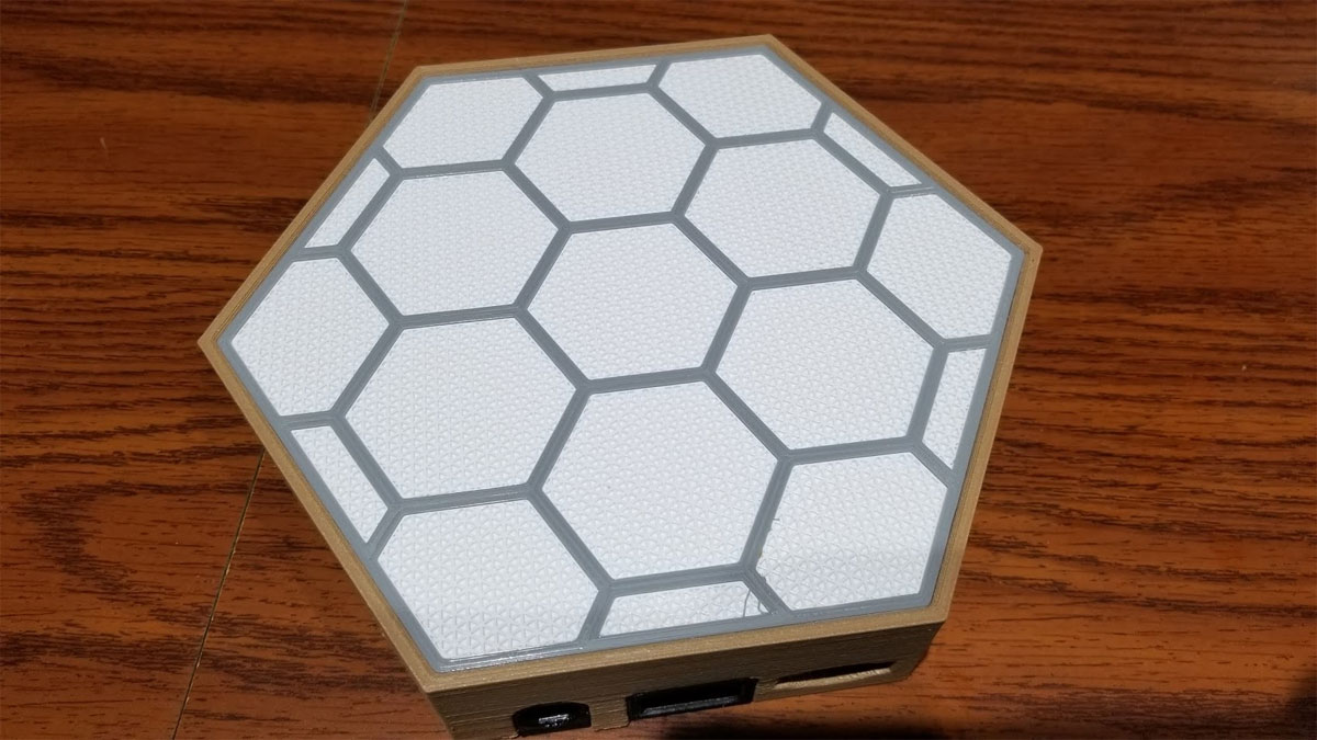
I printed the sides in Hatchbox Wood PLA using a 0.6mm nozzle, and the rest of the parts were printed with a 0.4mm nozzle in regular PETG. The front screens are printed with a texture and I did a quick write up of how to use that method here.
Although I'm happy with how my lights went together and work, I welcome any ideas on improving it, or remixes. One area I thought could be improved was how the LED's strips are clipped together where they end in each box. Since building mine, I went back and updated the design of the clip to make the bend in the LED strips less sharp (since the LED strips should not be bent at a sharp angle which can damage them). There are other areas which could be improved as well, like the complexity of the design and implementing the physical buttons. If I make further updates I will post them either here or on Thingiverse.
Finally, like many things, there are no guarantees, and I make none with respect to this design. Note that this requires a bit of understanding of electronics and Arduinos, as well as soldering. For safety I recommend using a fuse of some type, since there is plenty of room inside the boxes for any type of commercial fuse holder, and they are cheap. If you use a printed fuse holder, please read the comments related to that thing, which suggest printing in a high temp fire retardant filament, and then decide if you want to use it or not. Please also note that depending on how many LED's you use, the maximum current and therefore the appropriate gauge wire, power supply choice, fuse choice, switch and DC connector components will change (ex: more LED's = more current which means thicker gauge wires and more robust componets should be used). Point is, there is no one size fits all for this, or any bespoke LED setups, and many variations are possible. The important thing is to be safe and use your best judgement. Please do any required research and seek help if you are not sure about the why or how of something. I am not an electronics engineer, and I don't claim to be an expert on this stuff, only a hobbyist.
If you make one of these, it is at your own risk.
Before I get to far though, here is a Bill of Materials for these HexLED panels. Note - some of the links below are Amazon Affiliate Links. This means that, at zero cost to you, I will earn an affiliate commission to support this site, if you click through the link and finalize a purchase. I tried to link to the actual items I have bought, or if they are not available, similar items which I would buy based on value, but they are by no means the only options that will work.
Now on to the show...
I will provide links to the parts I used, however you should decide if you want to use the same parts or not, if you plan to make this or something similar. The STEP files are available on Thingiverse for those who want to modify and remix this to use other components. If you have some better components in mind please let me know.
This webpage is a build log, describing how I assembled my HexLED Panels. These panels were inspired by NerdForge's HexaLeaf LED Panels, and they use his code, and a similar electronics design, with the primary difference being these can be fully printed (including the screens) and have a few additional features. His code works very well, so big thanks to NerdForge for sharing his project! I suggest that if you plan on making this, and using his code, please check out his YouTube channel and consider supporting his projects on Patreon (https://www.patreon.com/nerdforge). I'm sharing the design for my version of the physical parts on Thingiverse and possibly Cults3D, as well as the STEP files, so others can hopefully improve the design.
Most of the assembly is straightforward but there are a few things which made me go back and re-work it (like noticing the LEDs were a bit less bright towards the end of the string, causing me to add some power injection points). Due to the tight fit on some parts, before I printed anything I calibrated the flow on each machine I was using to print, for each filament type being used (see here and here). I also measured the horizontal expansion for each filament, on each machine, to get the parts as closely fitting and to spec as possible. I use a simple 5x25x25mm test cube with a 10x10mm hole in the center to do this, using a method similar to what is described on the mattshub link, but any simple test cube will work. I can't say if this was necessary, but I can say that everything fit.
I printed the sides in Hatchbox Wood PLA using a 0.6mm nozzle, and the rest of the parts were printed with a 0.4mm nozzle in regular PETG. The front screens are printed with a texture and I did a quick write up of how to use that method here.
Although I'm happy with how my lights went together and work, I welcome any ideas on improving it, or remixes. One area I thought could be improved was how the LED's strips are clipped together where they end in each box. Since building mine, I went back and updated the design of the clip to make the bend in the LED strips less sharp (since the LED strips should not be bent at a sharp angle which can damage them). There are other areas which could be improved as well, like the complexity of the design and implementing the physical buttons. If I make further updates I will post them either here or on Thingiverse.
Finally, like many things, there are no guarantees, and I make none with respect to this design. Note that this requires a bit of understanding of electronics and Arduinos, as well as soldering. For safety I recommend using a fuse of some type, since there is plenty of room inside the boxes for any type of commercial fuse holder, and they are cheap. If you use a printed fuse holder, please read the comments related to that thing, which suggest printing in a high temp fire retardant filament, and then decide if you want to use it or not. Please also note that depending on how many LED's you use, the maximum current and therefore the appropriate gauge wire, power supply choice, fuse choice, switch and DC connector components will change (ex: more LED's = more current which means thicker gauge wires and more robust componets should be used). Point is, there is no one size fits all for this, or any bespoke LED setups, and many variations are possible. The important thing is to be safe and use your best judgement. Please do any required research and seek help if you are not sure about the why or how of something. I am not an electronics engineer, and I don't claim to be an expert on this stuff, only a hobbyist.
If you make one of these, it is at your own risk.
Before I get to far though, here is a Bill of Materials for these HexLED panels. Note - some of the links below are Amazon Affiliate Links. This means that, at zero cost to you, I will earn an affiliate commission to support this site, if you click through the link and finalize a purchase. I tried to link to the actual items I have bought, or if they are not available, similar items which I would buy based on value, but they are by no means the only options that will work.
- 6x M3x10mm screws per box
- 2x M3x16mm screws and M3 nuts with threadlock for the fuse holder
- A switch, I used the larger AC 250V/6A 125V/10A rated switch in the assortment here. Note that this switch is not DC rated, so you should use your own judgement on if this switch or any switch would be appropriate for your project.
- 5.5 x 2.1 MM 10A DC Power Jack with 18AWG leads attached similar to these.
- Optional (since the connections between LED strips could be soldered instead) - 12x male and 12x female JST SM 4-pin connectors with wires similar to these (only using 3 of the pins, but these seem easier to find pre-wired - get 3 pin if you can find them though). Also note that these are 22awg, so if you need to use a lower gauge wire, it would be better to solder the the connections between LEDs, or find different wired connectors with an appropriate gauge wire, but this is an example similar to what I used: https://www.amazon.com/gp/product/B075K3M1TB/
- Mini PCB breadboard (amazon item B081MSKJJX)
- ESP32-S Note that any ESP32-S should work, and really an ESP32 should too since this is not using bluetooth, but note that there is some variation in pinouts on the ESP boards (or so I have read), so make sure you can either read the pinouts on the board or it has some documentation.
- 4 Channel Logic Level Converter Bi-Directional Module 3.3V to 5V (amazon item B088TNGBQ7)
- WS2812B ECO RGB 60Pixel/m Flexible White Strip (NON-waterproof) (amazon item B088FJF9XD)
- Appropriate fuse and fuseholder (something like this or this). Read more below under "Step 4".
- If using the printed fuse holder see parts info here (see the thing comments regarding fire resistant filaments too): https://www.thingiverse.com/thing:1787609
- 2x 6x6mm momentary tact switch (5mm tall should work) - these are not implemented and may not be
- silicone jacketed wire, I use 20 awg wire for this project, but that is what I had on hand (wire size should be matched to the current load and length of wires).
- Heat shrink wrap, various sizes (some needs to be large enough to fit on the ends of the LED strips to cover the solder points).
- Appropriate power supply for your LED's. I used a 5V 4A UL Listed supply, which is under powered if I were to run all the modules with white, but otherwise seems OK.
Now on to the show...
Step 1 - Layout and mark which knock-outs need to be removed
To start with though, I had to work out the layout of the boxes I wanted, and laying them out in a large flat and clear area worked well for that (I used a kitchen table and later the top of my freezer). Once the layout was figured out, I marked the inside of each of the side frames to note where I had to remove the knock-outs for the connectors. I was able to hide some poorly printed parts by strategically placing these in areas where they would be hidden. This let me hide areas where corners had lifted or I was not happy with the surface finish. It may have been a good idea to number each box or something at this point, but I didn't, and it was not a big problem figuring out what went where.
Step 2 - remove knock outs for the connectors
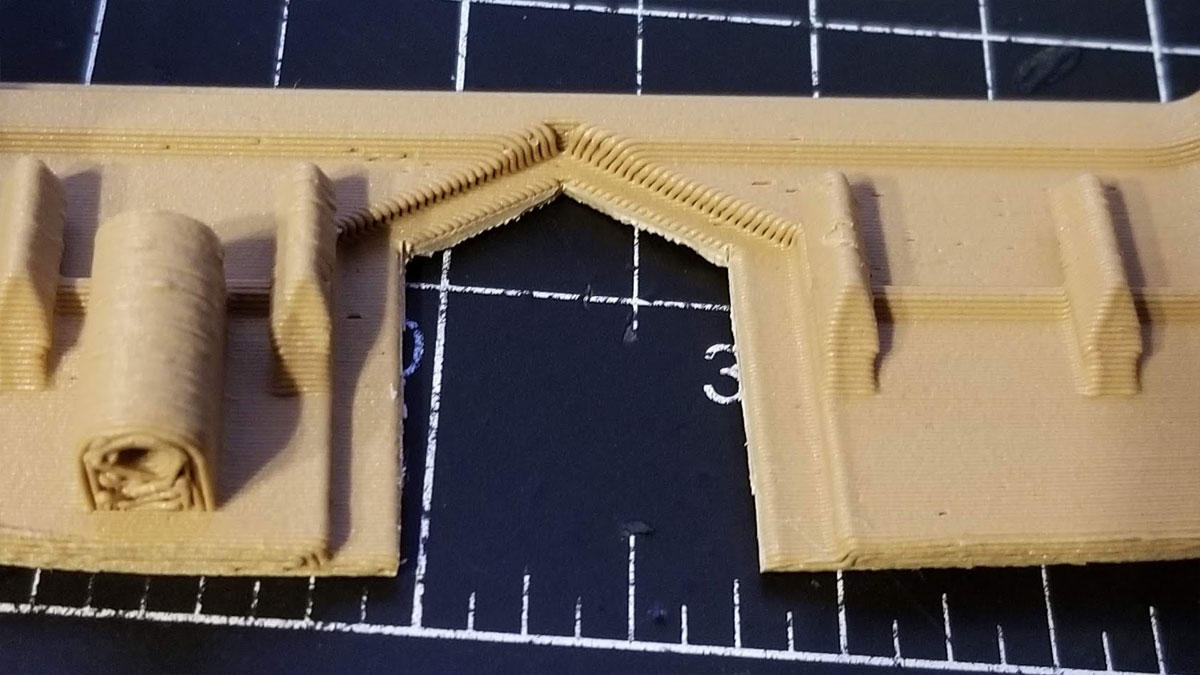
Once the layout is set and the spots were the knockouts need to be "knocked out" is known, the next step is I had to remove them. I found the best way to remove the knockouts was to score them with a razor from the inside (where it is easy to see the outlines of them), and then use a an edge cutter (same one as shown in the pic below) to clip out the knock out a bit at a time. I had to be careful when clipping the edges of the knock-outs because there would often be a crack which could sometimes extend into the model. To avoid that I took smaller bites with the clippers and sometimes cut only one side and just snapped the other side off by working it back and forth. When I got to the angled part I used some long nose pliers and twisted those out, though I think that only worked well because of the softness of wood PLA (it may require deeper scoring if using regular PLA). Then I used a razor to clean to the edges of the knock out. This method was the quickest and it really didn't need to be pretty since it is not seen. I just checked the fit on each one and when it was good, moved on to the next one.
Step 3 - Install the LEDs
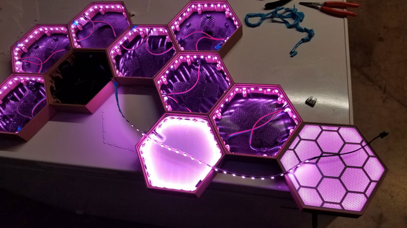
So once I had all the knock-outs knocked out, I installed the LED's in each box. I found it was easier to do this before installing the connectors since I was able to work on each box separately at this point. To do this I cut the LED strips to lengths of 30 LED's (using a 300/5m 5V RGB LED Strip) and then prewired / soldered wires with JST SM connectors to the sections, covering the exposed solder points with heat shrink. A note on the JST SM connectors with wires; I found 4-pin connectors with wires were easier to buy than 3-pin, so I just cut out one of the wires from the 4-pin connector (the blue one) and went with that. 3 pin JST SM connectors with wires would be better, I just could not get them easily. When prewiring the LED sections, I initially decided to use a female connector on the input side and male connector on the output side. It was important to maintain that arrangement of male and female connectors for all the strips. Note that some LED strips come pre-connected to JST SM 3-pin connectors, and have additional wires connected for power injection soldered to the strip. I had to remove any of the factory connectors from my LED strips since they were not the correct type (3 pin while I used 4 pin), and the additional power wires they added to the strips, made the ends too thick to go into the clips which connect the ends.
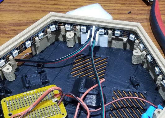
When installing the strips in the boxes, I had first decide where to place the ends. The ends should be located so there is enough wire to reach the previous and following boxes, so it is something that takes a bit of thought. Once the location for the ends was decided, I installed the the part which holds the ends together in one of the recesses for it (this of course is one that has not been knocked out). Then I pulled up some of the backing for several inches to make a tail that would hang out (this is later pulled to seal the LEDs in position when the position is set). To get the LEDs installed in their channel, I worked from one side, around the box and just took the time to get them in there. I had to be careful not to bend the LED strip sharply since that could damage them. If any of the retainer clips broke off, it was not a big deal since the LED's have tape on them anyway. Once all the way around the box, the loose tail was pushed into the clip which joins the ends of the strip. I had to be sure not to bend the strip at a severe angle or damage the LED strip while installing it. The LED's that sit in the corners of the boxes simply float, and I did not attempt to press them down, since that could damage the LED strip. Then I tested the strip before sticking them down. When everything looked OK I just pulled the loose backing strip (carefully since it can break), and stuck the LED strip in the final position. If the backing strip did break and the LED's looked fine I typically would just leave them like that since they won't get any heat sinking benefit from the plastic model anyway.
One note on installing the LED strips. The only module which requires the strips to come together in a particular place is the electronics module. On this one the LEDs must join at the point opposite the side with the switch, DC jack and fuse.
Step 4 - Electronics module
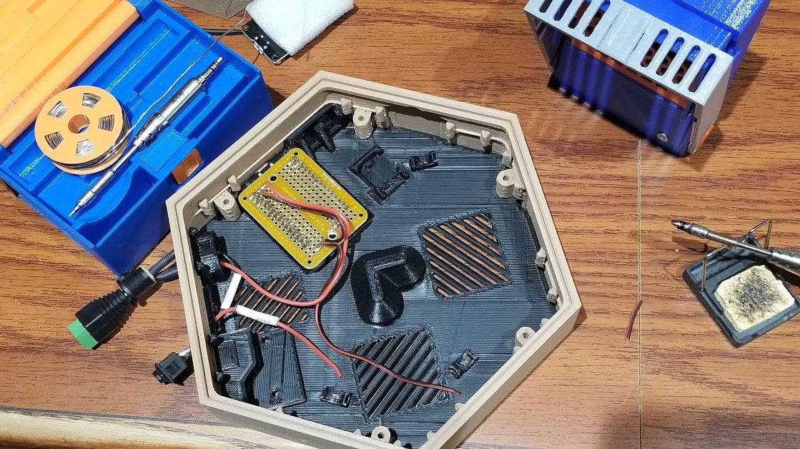
Assembly of the electronics module was not difficult but it required a good bit of soldering. The ESP32-S I used already had pins pre-soldered. I did mine a bit differently, and learned a few things so I will note where I would have done things differently next time.
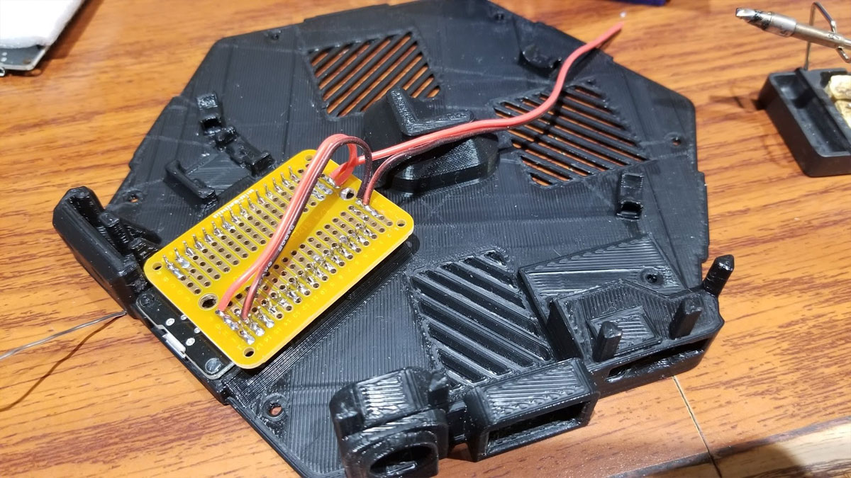
I I first pressed the ESP32-S into place and melted the pins with a hot flat head screwdriver to hold it in. It was a bit hard to get the ESP32 fully seated but it did go in, and it's important for the alignment of the connector that it fully seat. After that I installed the breadboard, which only goes in one way. Even though I won't be using most of the pins I soldered them to the breadboard anyway (In hindsight, I would have soldered the power connections to the breadboard prior to soldering it to the ESP32 since that would have allowed me to make sure there was no excess solder or wires poking out on the bottom of the board near the power section of the board).
Then I soldered the power and ground pins for the ESP32-S over to the available rows at the far end of the breadboard, since that is where I decided to make the power bus for all the positive and ground connections. This was just my preference and there are a ton of ways to do this, but it seemed to be the tidiest way, and I had some rows of free pins left at the end of the board so why not use them? Alternatives would be to use WAGO type connectors or solder the power wires together and not use the board to bus the power lines together.
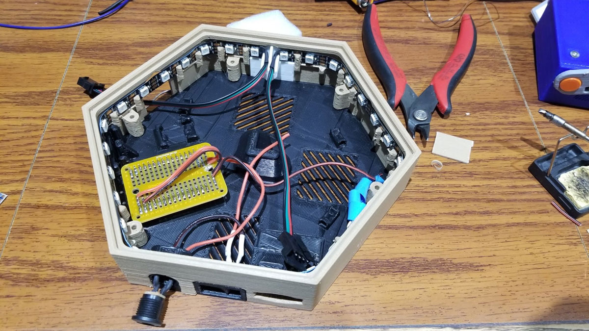
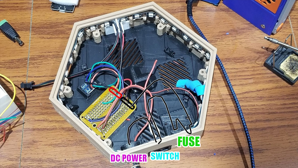
I then ran some power input wires from the breadboard (where I soldered the power positive and ground connections at the end of the board) over to a DC power connector, a switch and the fuseholder. These are shown above, note that the ground wire has the fuse and toggle switch on it. The DC connector positive connects directly to the breadboard on the designated positive power rail, while the ground from the breadboard goes to the fuse, which goes to the switch and then to the DC jack ground. The toggle switch presses in and snaps in place. I updated the design since these pics were taken with a larger toggle switch but it installs the same way. The DC jack was pressed in and I used some glue to secure it (in hindsight I should have also installed the nut that came with the connectors also, but note that the nut needs to go in before soldering everything). The fuse holder was assembled using the crimped connectors (they only go one way but it's easy to install them upside down). The fuseholder I used was secured with two M3x16mm screws with nuts on top, and I used some lock-tite on the nuts to keep them secure (sorry no pics of that). Other types of commercial fuse holders could also be used and secured inside the case using zip ties or glue.
Regarding the printable fuseholder, I have read some criticism of it in the comments for that thing, and am not sure how well it will perform in this application but, I am trying it out since it is a pretty low amperage light. It was recommended to print the fuse holder using a higher temp flame retardant filament, and I have seen a few out there like this, which I may try. I am using PETG on mine for right now. There is room in the electronics module for other types of commercial fuseholders (like this and this), which may be better for this design, and again this is at your own risk so if you make this, use your best judgement. If you use a fuse, get a good quality one, since the cheap assortments are sometimes no better than any old wire.
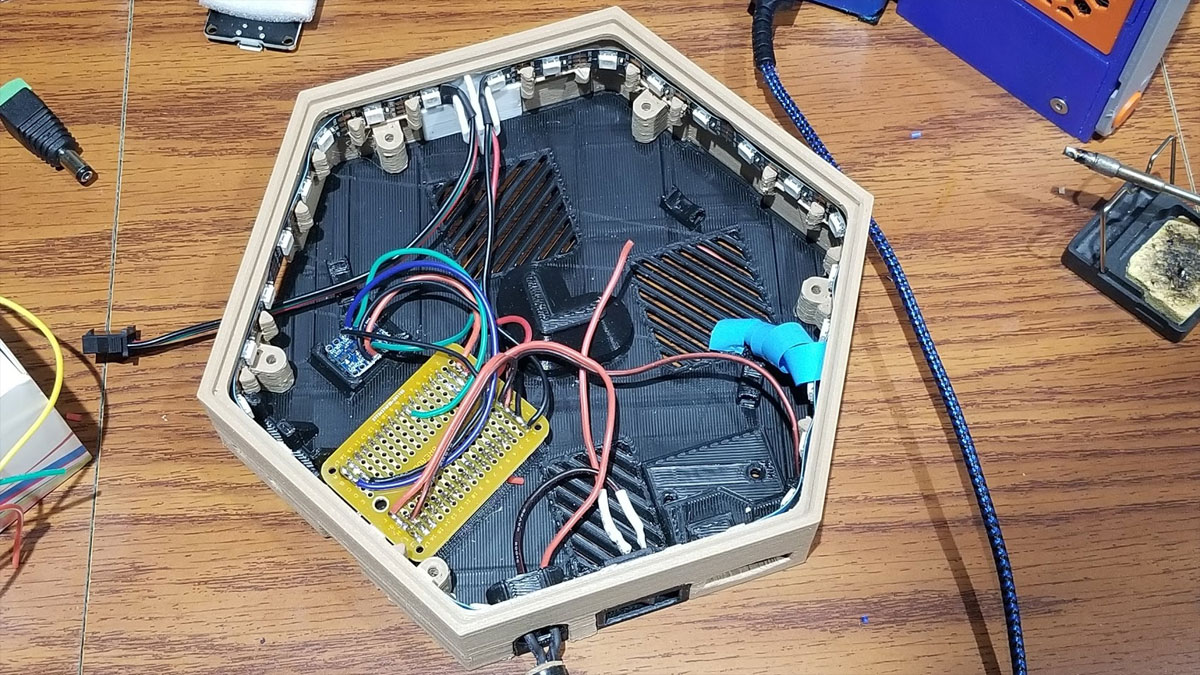
Now things begin to get less simple. I pre-soldered all the connections to the 4 Channel Logic Level Converter Bi-Directional Module which takes the 3.3V out from the ESP32-S and boosts it to 5V which can work with the LED strip. The Logic Level Converter therefore needs to be connected to ground, 3.3v, 5V, Pin 19 (used to control the LED's) and the control wire from the LED strips (on the in side of the strips). I followed NerdForge's schematic here on these connections, except since I am using 5V LEDs with a 5V power supply I omitted the 12V to 5V stepdown converter. I chose to connect the wires to the Logic Level Converter middle pins since the converter module snaps into position on the base (it helped to slightly bend out the tabs on the holder, to assist it snapping in place). I have updated the design with more robust clips for the logic level converter board since I had one clip break, but it should still be possible to install, but it may be necessary to try and open the clip a bit with some pliers while getting the board in place. I added a dab of glue to the end to hold my logic converter in place since the clip snapped.
In the PIC below most of the wiring is completed, aside from a few connections, and the fuse is not yet installed. I don't have pics of the fuseholder being installed, but it just goes inline with the ground between the switch and the board ground bus rail. The two pics below are the same but the 2nd one shows how the ground of the DC power, switch and fuse are connected to the breadboard.
At this point I installed the firmware and tested it. I won't get into that here but I will say that I had to be sure to only connect the one box with the electronics (with no other LED strips other than one one it had) to the PC USB since I didn't want to fry my USB port by trying to pull too much current from it. It would actually be safer to program the ESP32-S without any LED's connected, however I was able to do it multiple times without a problem (with the 30 LED's connected to it in the box as shown above). Though I'm not doing a walkthrough of installing the Nerdforge code on an ESP32, I did post some info here on getting the Blynk phone app working with the code from Nerdforge.
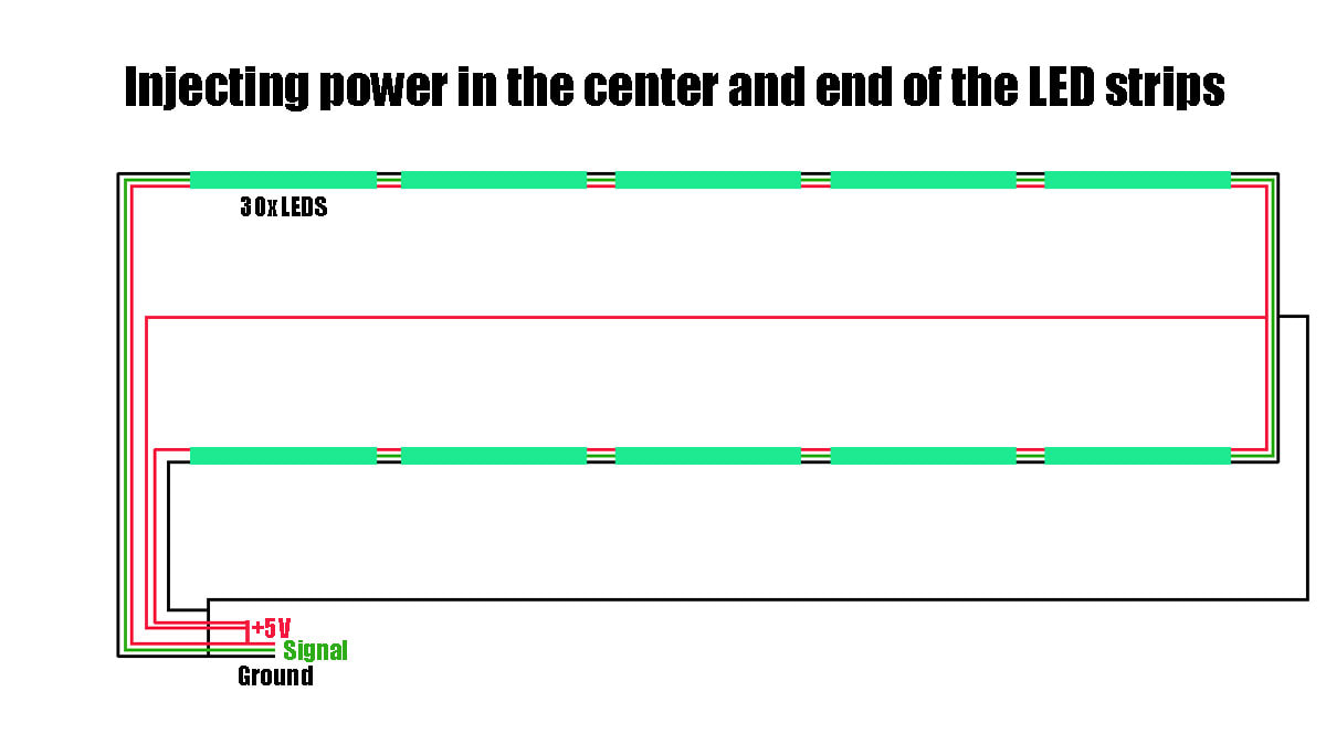
Here is where I could have saved myself some time and installed two additional pairs of DC power and ground wires, for injecting power in the middle and end of the strip. Whether or not it may be helpful to inject power on the strip depends on how many LEDs are used, and I may have only needed to inject power at the end or middle to fix dimming towards the end of the strip, but I added power to both places. I found this video which explains the issues with powering LED strips and also how to do power injection. Below is a diagram of how I did that. I simply soldered the ends to the positive 5V and ground buses on the breadboard for these power extension wires. The other ends were made into simple connectors which would bridge or terminate the LED strip, passing through the signal while injecting power from the wires going back to the breadboard. Note that the power injection wires are only for the positive 5V and ground connections on the strip, they do not connect to the signal wires.
Here is where I could have saved myself some time and installed two additional pairs of DC power and ground wires, for injecting power in the middle and end of the strip. Whether or not it may be helpful to inject power on the strip depends on how many LEDs are used, and I may have only needed to inject power at the end or middle to fix dimming towards the end of the strip, but I added power to both places. I found this video which explains the issues with powering LED strips and also how to do power injection. Below is a diagram of how I did that. I simply soldered the ends to the positive 5V and ground buses on the breadboard for these power extension wires. The other ends were made into simple connectors which would bridge or terminate the LED strip, passing through the signal while injecting power from the wires going back to the breadboard. Note that the power injection wires are only for the positive 5V and ground connections on the strip, they do not connect to the signal wires.
Step 5 - Connect the modules together
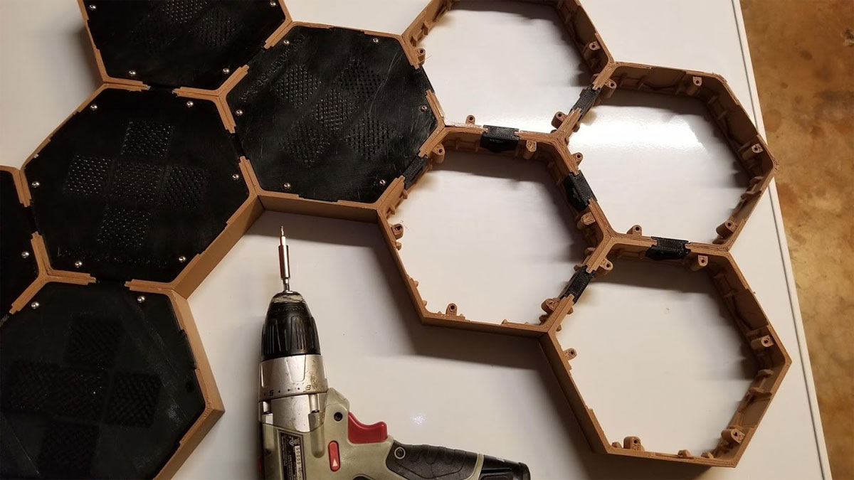
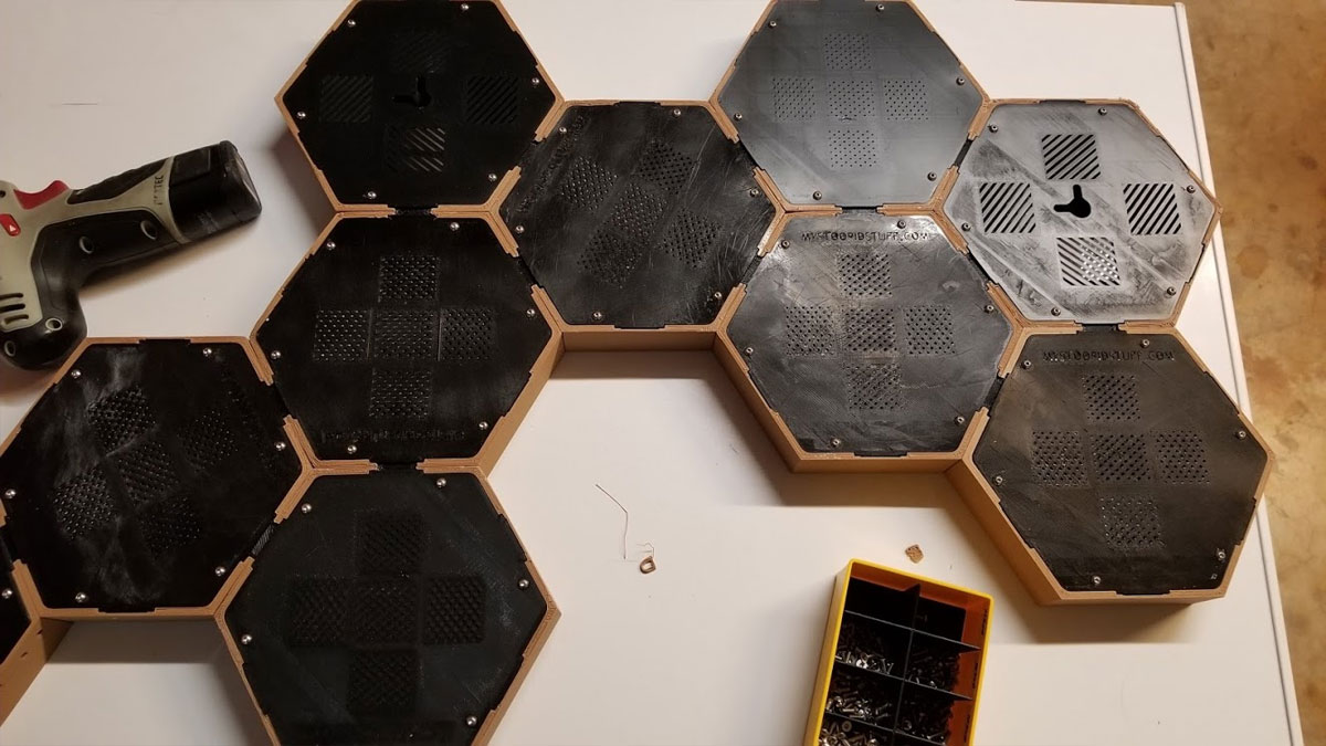
Once the electronics box is completed, programmed and tested, the next thing I had to do was assemble the design according to the layout I had picked previously. I did this by laying out the sides components face down on a large flat surface (in my case it was the top of a freezer), and then I just added connectors between each one until they were assembled. Then I installed the back covers with 6x M3x10mm screws for each cover. There are several types of covers which were designed with the idea to cut down print time and resource usage, so there is some thought that needs to be put in here. I printed two covers with wall hanging holes, in addition to the electronics module cover which has a wall hook hole. The rest are all a plain quick printing cover. All the covers have one or more cable management points which in practice I did not bother with but they were intended to secure the loose cables with small zip ties. Because there were a lot of screws to install the covers, I used a power screwdriver with the torque set way down, and used an extension for the small 4mm bits I was using, this saved quite a bit of time.
Once the covers were mounted, I routed the wires through each module and connected them up. Here is where I would have installed the power injectors to the middle (between the 5th and 6th modules) and end of the strip, routing the wires through the intermediate modules. In reality I had to go back and add the power injectors later which was a bit of a hassle.
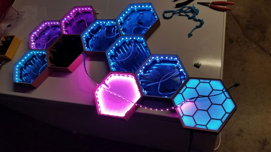
Once the LED's are wired, I double checked everything, including that the wire colors matched on all connections (that is I didn't have ground connected to +5V anywhere), that the arrows on the LED strips were correct for where power was going in from the previous module and going out to the next one down the line, and that I had my fuse installed. This can be tedious and is alot like following a wire through from end to end but I thought it would be better than possibly shorting something and blowing out some LED's. Since I was using a 5V 4A power supply with this (which is under powered but what I had on hand), I used a 5A fuse to test with. Once everything was checked, and re-checked, I tested it with my 5V DC power supply and confirmed all the modules were working as they should.
Step 6 - Final assembly
I was almost done at this point, the last steps are to install the inside light filters which help keep the light from getting too lost on it's way out the front of the modules. These filters are printed to be very thin and flexible and just pop in with some help (they are not glued). These inside filters are designed to be universal to any of the boxes I had to work them into position. The inside filters have two cutouts, one is rectangular which accommodates the DC power connector on the electronics module, and the other is a wire cover which is positioned wherever the wires for the LED's come together in each module. I found it helps when working these inside filters into position, to push the LED's out of the way just a bit and work around the module from the wire clip.
Once the inside filters were installed I just popped in the outer (front or top) filters which covered the modules and LED's. These went in with bit of pressure and also did not require glue to stay in. I also tested the current draw and found that it was between 2 and 4.17A (white) which was the max my small power supply could do.
Once the inside filters were installed I just popped in the outer (front or top) filters which covered the modules and LED's. These went in with bit of pressure and also did not require glue to stay in. I also tested the current draw and found that it was between 2 and 4.17A (white) which was the max my small power supply could do.
Finally I mounted it on the wall. This is pretty simple of course but I have been using a trick with the wall hangers since in my case the hangars are not on the same level (they were offset a bit). To prep the hangers, I first tested 14 gauge nails to be used with them, to make sure they would go in, and found that I had to run a drill though to clean them up just a bit. I also made sure the hangers moved freely in the pockets they would go in, and had to clean out some remaining supports to get them to move freely.
Next I applied the 3M Command Strips on the hangers and then added a very small, just enough to hold it barely, size piece of double sided foam tape (or masking tape that is rolled in a loop to make it "double sided" - see pics), on the side of the hangers that will face the panels. The idea of this is to hold the hangers in position while the whole works is put into place and leveled. After positioning the hangers with the weak double sided tape, I then peeled the wall side off the Command Strips, carefully positioned the panels using a small torpedo level, and when it looked good I pressed the whole thing to the wall which stuck the Command Strips. Then, because the very small amount of foam tape (or masking tape) which was used to hold the hangers to the panels, was easy to dislodge, I was able to remove the panels from the wall, leaving the hangers in position. Next, I just had to give the hangers a good press'n down, and installed the 14 gauge nails and hammered those home. Finally I replaced the panels (this time without the double sided tape to hold the hangers). And that was it, connected power and done.
Next I applied the 3M Command Strips on the hangers and then added a very small, just enough to hold it barely, size piece of double sided foam tape (or masking tape that is rolled in a loop to make it "double sided" - see pics), on the side of the hangers that will face the panels. The idea of this is to hold the hangers in position while the whole works is put into place and leveled. After positioning the hangers with the weak double sided tape, I then peeled the wall side off the Command Strips, carefully positioned the panels using a small torpedo level, and when it looked good I pressed the whole thing to the wall which stuck the Command Strips. Then, because the very small amount of foam tape (or masking tape) which was used to hold the hangers to the panels, was easy to dislodge, I was able to remove the panels from the wall, leaving the hangers in position. Next, I just had to give the hangers a good press'n down, and installed the 14 gauge nails and hammered those home. Finally I replaced the panels (this time without the double sided tape to hold the hangers). And that was it, connected power and done.
Finally, to hopefully help avoid pitfalls, here are some problems or annoyances which may help to be mindful of:
That's it, I hope this was helpful info. There may be a better way I didn't think of to assemble these panels, so if you have an idea how it could be improved, please leave a comment below or at Thingiverse.
- Wood PLA is stringy and abrasive, if using it, try a 0.6mm steel or hardened nozzle as I did (had no problems with it). It can help to slow it down and it pays to get the retraction tuned beforehand as well.
- Most parts don't need supports, but some will, no avoiding it. They can however be minimized by using a low density (10%), high overhang angle (>70%), and simple pattern like "Lines". The Electronics Base needs the most and will be hardest to clean, but using minimal supports will make it much easier.
- Cura's support blocker can be used to avoid supports in the cable management points.
- I only used supports "touching the build plate" on the regular side pieces (the electronics box side needs them everywhere).
- The maximum current (all LED's on) will depend on the number of LEDs being used. The max current will dictate what power supply, wire gauge and fuse value is used. Please make your own decisions on these items, and don't go with what I used, since every project is different, and to be safe, the wire gauge, fuse value and power supply should match your project (not mine).
- For my panels, I used a printed fuse holder design from another user here (https://www.thingiverse.com/thing:1787609). However if you plan to use it, or something similar, please see the comments for that thing, and note that it was suggested to print using a high temperature, flame retardant filament. If you have a concern, I would suggest instead to use a commercially available fuse holder, since the case has plenty of room and there are versions provided without the fuse and button holes.
- Use heat shrink to insulate the ends of the LED strips once they are soldered to wires to extend them. Also, be careful not to bend the LED strips sharply which will damage them. The LEDs that fall in the corners of the boxes can "float", they should not be pressed into the corners, which could bend the LED strip too sharply.
- It would be a good idea to bench test the setup prior to assembly, and see if adding additional power points to the middle or end would help. I had to go back and add power to the middle and end, after I thought it was done. I could have saved time by doing a test first. Also, use an appropriate gauge wire for any power extensions needed.
- The buttons are not implemented, so I included a version or the electronics box side which has them blocked out. The buttons are for future expansion which may or may not happen (even if I do enable them I don't know if I would get permission to post derivative code).
- I made a quick guide on how to set up Blynk for NerdForge's code here. If I were to do this again, I would check to see if I could make it work with WLED (its still something I want to use for this). If I do get WLED working for this, I will update this page with a link for a how-to.
That's it, I hope this was helpful info. There may be a better way I didn't think of to assemble these panels, so if you have an idea how it could be improved, please leave a comment below or at Thingiverse.
