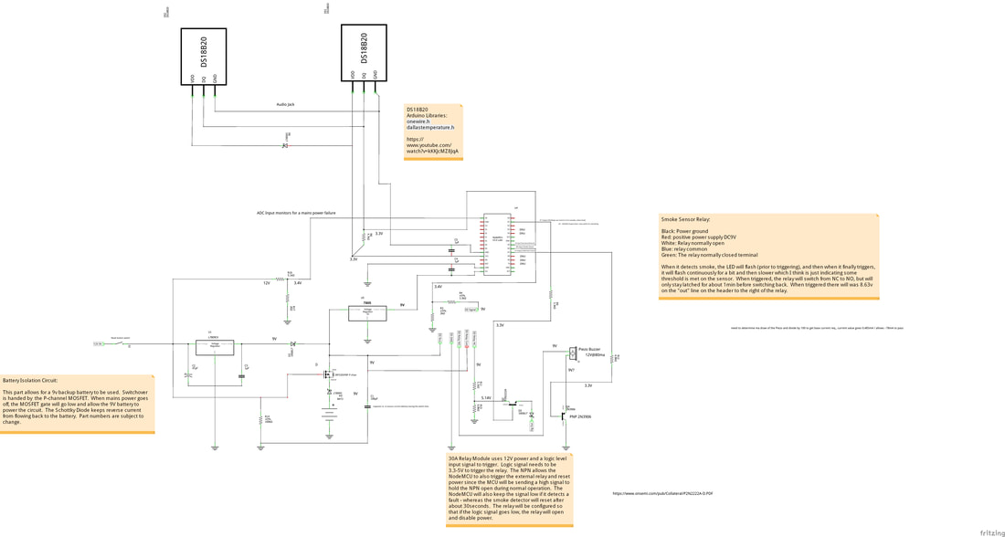
The circuit diagram is just an outline for what I am hoping to build. The quality of the pic above sux and I can't seem to fix that since the decent (readable) image I uploaded is getting optimized or something when it is posted. I have not used the NodeMCU and my Arduino skills are really rusty, but there are enough tutorials out there and libraries that should help with the hardest parts of making this happen. The following are the major components I plan to use:
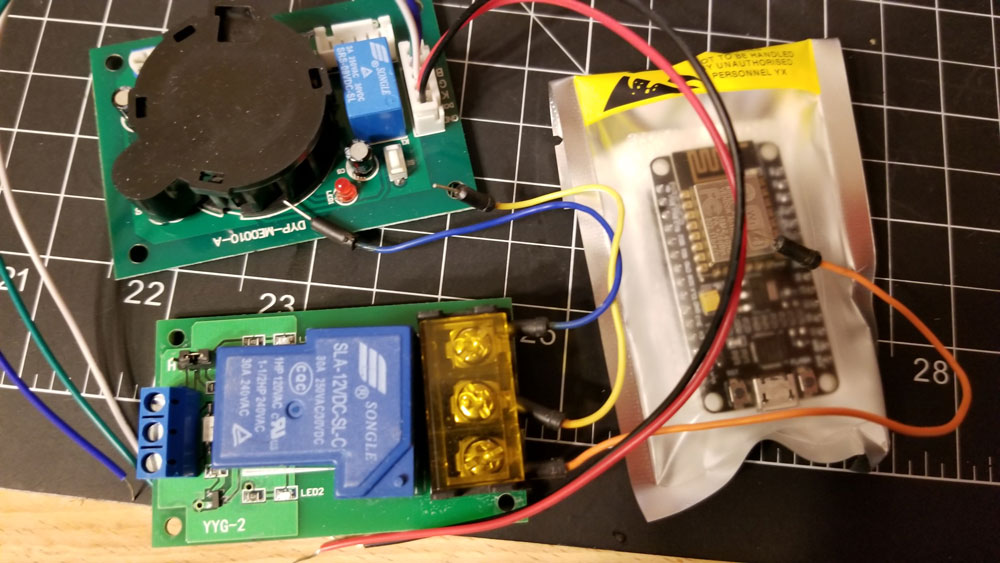
- 9V Smoke Detector Relay (Ebay: Smoke Sensor Module Smoke Detector w/ Relay Output J6J4)
- 30A 12V Realy with logic level input (Ebay: 5V/12V/24V 30A Optocoupler Isolation Relay Board Module High/Low Trigger)
- NodeMCU (ESP8266)
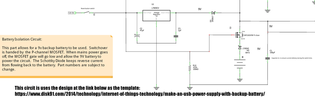
The first part of the project was to set up a battery backup circuit. I wanted to have it run from a 9v battery in the event that mains power was down. So I found some examples of exactly what I was looking for, and used them. The P-Channel MOSFET is apparently ideal for this task since it normally will conduct when the gate is at 0v (assuming that the Source voltage is positive). Below are the links to the info I used or found helpful for the battery backup part of the design so far:
Good explainations of P-channel MOSFETS:
https://www.baldengineer.com/p-channel-mosfet-tutorial-with-only-positive-voltages.html
https://www.youtube.com/watch?v=14mYnsWK7QM
Example battery backup circuit designs - the design below is duplicated from these:
https://electronics.stackexchange.com/questions/219353/battery-backup-supply-switch-over-design
https://www.disk91.com/2014/technology/internet-of-things-technology/make-an-usb-power-supply-with-backup-battery/
https://www.eevblog.com/forum/chat/battery-backup-circuit/
Since I have not used P-Channel MOSFETs in the past, the youtube videos saved my sanity when I thought I had screwed up (but hadn't). I had also read several things online that put me on a wild goose chase for a "depletion" mode P-Channel MOSFET - which are like hens teeth - and not necessary. For some reason, almost all of the P-Channel MOSFETs available are "enhancement" mode, so the depletion mode type are unavailable or very expensive (in that small quantities are not available). Anyway enhancement mode work just fine for this it seems, and so once I got back on track with that, I was able to order some and give it a test.
P-Channel MOSFET notes...
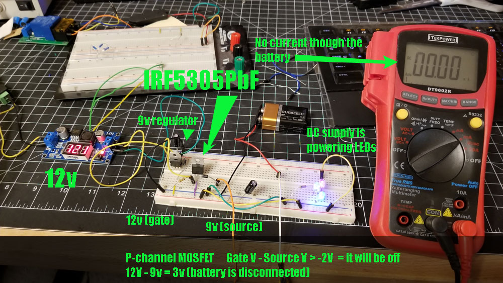
The pics further down show my test setup with the mains power (the voltage regulator on the left) turned on, and a backup 9v battery connected. The P-channel MOSFET is the "IRF5305PbF" and the pinout is Gate / Drain / Source (looking at the labeled side of the part). This part has a "Gate Threshold Value" of -2 to -4 volts (that's right negative voltage). Specifically the Gate Threshold Voltage is the voltage difference between the Gate and Source. The link above for the baldengineer.com site has a good explanation of what it takes to trigger a P-Channel MOSFET, which I understand (in this case) to be basically this:
Gate Voltage - Source Voltage > Gate Threshold Voltage = OFF
Gate Voltage - Source Voltage <= Gate Threshold Voltage = ON
There may be more to it than that, but that's how I understand it now. So in my case, the Gate would be 12V and the Source would be connected to my 9V battery. The drain is connected to the Vcc going to the LED's in this test case. Therefore, when the mains is connected and there is 12V input to the device, the battery should be disconnected completely (12V - 9V = 3V > -2V) where -2V is the higher end of the Gate Threshold Voltage from the datasheet. If mains power is lost then the 12V on the gate will drop to zero and the battery should be allowed to take over (0V - 9V = -9V < -2 (to -4)V) so the P-channel MOSFET should be ON, connecting the 9V battery to the Vcc Supply line for the rest of the circuit. I tested this and it seems to work well, though I have left in the Schottky diodes to protect from reverse polarity on the battery (they may not be necessary but since I have volts to spare I am leaving them in). I probably could have used regular diodes for the reverse protection, I just wanted something to protect against an accidental, and brief flipping of the battery connector when installing it, I don't thing there is any point to the diode after the 9v regulator though and probably would remove that from the final design.
So here are some pics showing the testing - first the scenario where mains is on, and I don't want the battery connected at all. The multimeter is testing current flow from the battery positive to the P-Channel MOSFET source pin (there is a diode in there also). There is no current because the MOSFET is not conducting. Note that there is a 9v regulator but the gate is connected to 12v. The 9v regulator is fed by the 12v supply on the left which is also where I get the 12v for the gate, and the regulator outputs 9v into the power rail that the LED's supply from.
So here the test with the mains power on, supplying 12v to the circuit, and the LEDs (supplied from the 9v regulator) are also on. The battery is disconnected since the MOSFET is not conducting:
Gate Voltage - Source Voltage > Gate Threshold Voltage = OFF
12 volts - 9 volts > -2 (to -4) volts = OFF
Good explainations of P-channel MOSFETS:
https://www.baldengineer.com/p-channel-mosfet-tutorial-with-only-positive-voltages.html
https://www.youtube.com/watch?v=14mYnsWK7QM
Example battery backup circuit designs - the design below is duplicated from these:
https://electronics.stackexchange.com/questions/219353/battery-backup-supply-switch-over-design
https://www.disk91.com/2014/technology/internet-of-things-technology/make-an-usb-power-supply-with-backup-battery/
https://www.eevblog.com/forum/chat/battery-backup-circuit/
Since I have not used P-Channel MOSFETs in the past, the youtube videos saved my sanity when I thought I had screwed up (but hadn't). I had also read several things online that put me on a wild goose chase for a "depletion" mode P-Channel MOSFET - which are like hens teeth - and not necessary. For some reason, almost all of the P-Channel MOSFETs available are "enhancement" mode, so the depletion mode type are unavailable or very expensive (in that small quantities are not available). Anyway enhancement mode work just fine for this it seems, and so once I got back on track with that, I was able to order some and give it a test.
P-Channel MOSFET notes...
The pics further down show my test setup with the mains power (the voltage regulator on the left) turned on, and a backup 9v battery connected. The P-channel MOSFET is the "IRF5305PbF" and the pinout is Gate / Drain / Source (looking at the labeled side of the part). This part has a "Gate Threshold Value" of -2 to -4 volts (that's right negative voltage). Specifically the Gate Threshold Voltage is the voltage difference between the Gate and Source. The link above for the baldengineer.com site has a good explanation of what it takes to trigger a P-Channel MOSFET, which I understand (in this case) to be basically this:
Gate Voltage - Source Voltage > Gate Threshold Voltage = OFF
Gate Voltage - Source Voltage <= Gate Threshold Voltage = ON
There may be more to it than that, but that's how I understand it now. So in my case, the Gate would be 12V and the Source would be connected to my 9V battery. The drain is connected to the Vcc going to the LED's in this test case. Therefore, when the mains is connected and there is 12V input to the device, the battery should be disconnected completely (12V - 9V = 3V > -2V) where -2V is the higher end of the Gate Threshold Voltage from the datasheet. If mains power is lost then the 12V on the gate will drop to zero and the battery should be allowed to take over (0V - 9V = -9V < -2 (to -4)V) so the P-channel MOSFET should be ON, connecting the 9V battery to the Vcc Supply line for the rest of the circuit. I tested this and it seems to work well, though I have left in the Schottky diodes to protect from reverse polarity on the battery (they may not be necessary but since I have volts to spare I am leaving them in). I probably could have used regular diodes for the reverse protection, I just wanted something to protect against an accidental, and brief flipping of the battery connector when installing it, I don't thing there is any point to the diode after the 9v regulator though and probably would remove that from the final design.
So here are some pics showing the testing - first the scenario where mains is on, and I don't want the battery connected at all. The multimeter is testing current flow from the battery positive to the P-Channel MOSFET source pin (there is a diode in there also). There is no current because the MOSFET is not conducting. Note that there is a 9v regulator but the gate is connected to 12v. The 9v regulator is fed by the 12v supply on the left which is also where I get the 12v for the gate, and the regulator outputs 9v into the power rail that the LED's supply from.
So here the test with the mains power on, supplying 12v to the circuit, and the LEDs (supplied from the 9v regulator) are also on. The battery is disconnected since the MOSFET is not conducting:
Gate Voltage - Source Voltage > Gate Threshold Voltage = OFF
12 volts - 9 volts > -2 (to -4) volts = OFF
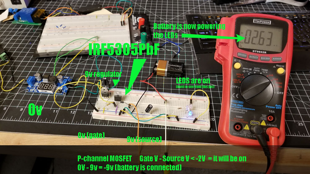
Next is the condition where mains power is down, and the battery must take over. It is the identical setup as above, I just turned off the 12v supply on the left. So now the gate voltage is dropped to zero, and the supply (where the 9v battery is connected is still at 9v). Note that the pics don't show the LEDs being on very well since these are color changing LEDs (what I had handy) and they transition so when I got the pic only one appears lit - but they were all on.
Gate Voltage - Source Voltage <= Gate Threshold Voltage = ON
0 volts - 9 volts < -2 (to -4) volts = ON
Gate Voltage - Source Voltage <= Gate Threshold Voltage = ON
0 volts - 9 volts < -2 (to -4) volts = ON
So that's pretty much that for the backup and power part of the circuit. The rest of it will be the hard part - programming the NodeMCU to do my bidding - and I am not sure if that will kill this project or not.

 RSS Feed
