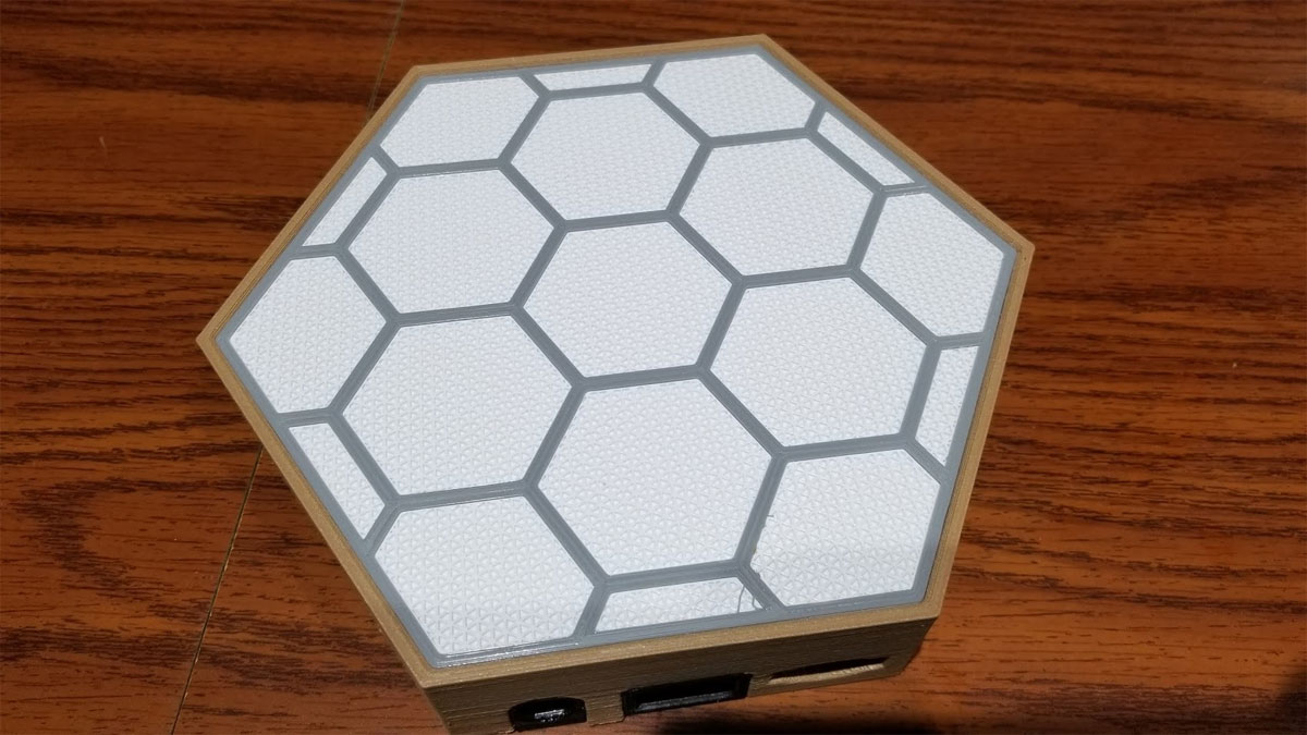
Many of the Hexagon LED panels require cutting sheet plastic for the front screens / light filters, but that can be difficult and expensive. Printing them can have mixed results and either requires a perfect top layer or a good bottom texture from the bed (and great squish since you don't want to see layer lines in the top surface). This method is an alternative which, instead of trying to get a perfect top layer, can hide some imperfections using a textured top surface.
The basic requirements are these:
In my case, I am using a model I created for my Hex LED panels, and it is designed to be printed using this method. Since a Hexagon is a Hexagon, it is probably possible to use these models with other designs as well. I am using a white and gray PLA which both print well at the same temp and their ideal flow is 1-2% different which was close enough. My printer uses a direct drive Titan Aero so filament changes are not trivial but I can still do them mid print if I take care.
The basic requirements are these:
- A model designed to be printed like this (with a solid printed part and a part which can be printed "as support")
- Optionally two colors of filament which are compatible (print at roughly the same temps and flow)
- The ability to do a filament change mid print (most printers can easily but there may be some extruder setups which make it harder).
- Cura slicer (others will work too I'm sure, but Cura is what I am showing here)
In my case, I am using a model I created for my Hex LED panels, and it is designed to be printed using this method. Since a Hexagon is a Hexagon, it is probably possible to use these models with other designs as well. I am using a white and gray PLA which both print well at the same temp and their ideal flow is 1-2% different which was close enough. My printer uses a direct drive Titan Aero so filament changes are not trivial but I can still do them mid print if I take care.
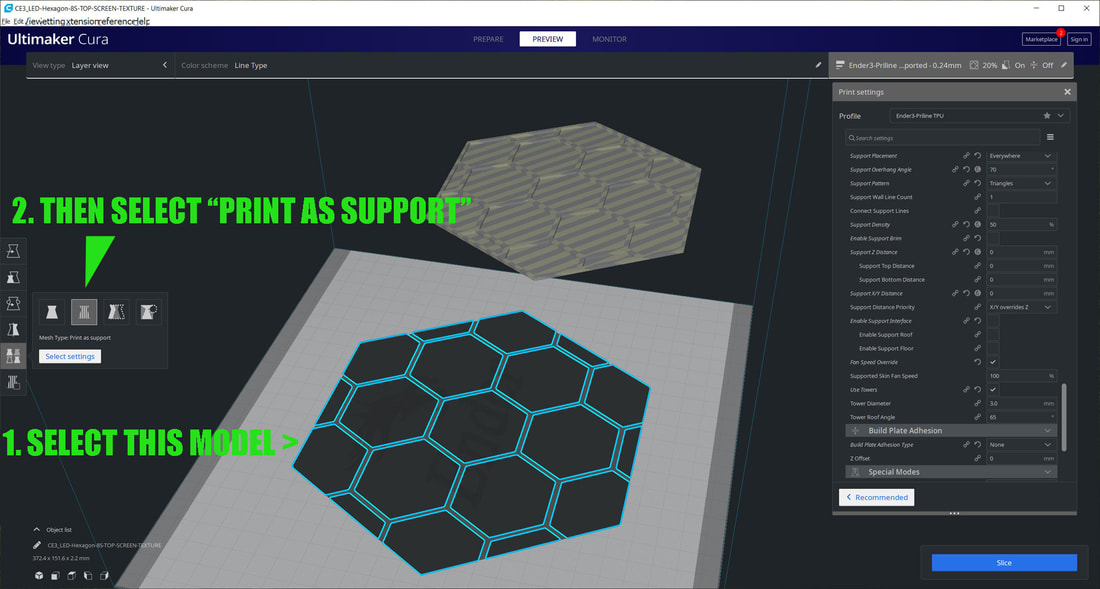
Step 1 - Load the models into Cura
Starting with a blank workspace in Cura, first load both models and don't worry if they don't fit (as long as one does it is cool). Then select the model which will be printed as texture and then select "Print as Support" as shown below.
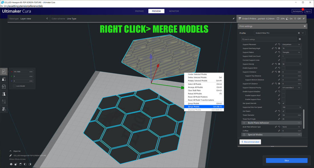
Step 2 - Merge the models
Now right click anywhere in the print area not on the models, and select " Select All Models" (or Ctrl+A). Then right click again (anywhere in the print area not on the models), and select "Merge Models". You will see the models become one model.
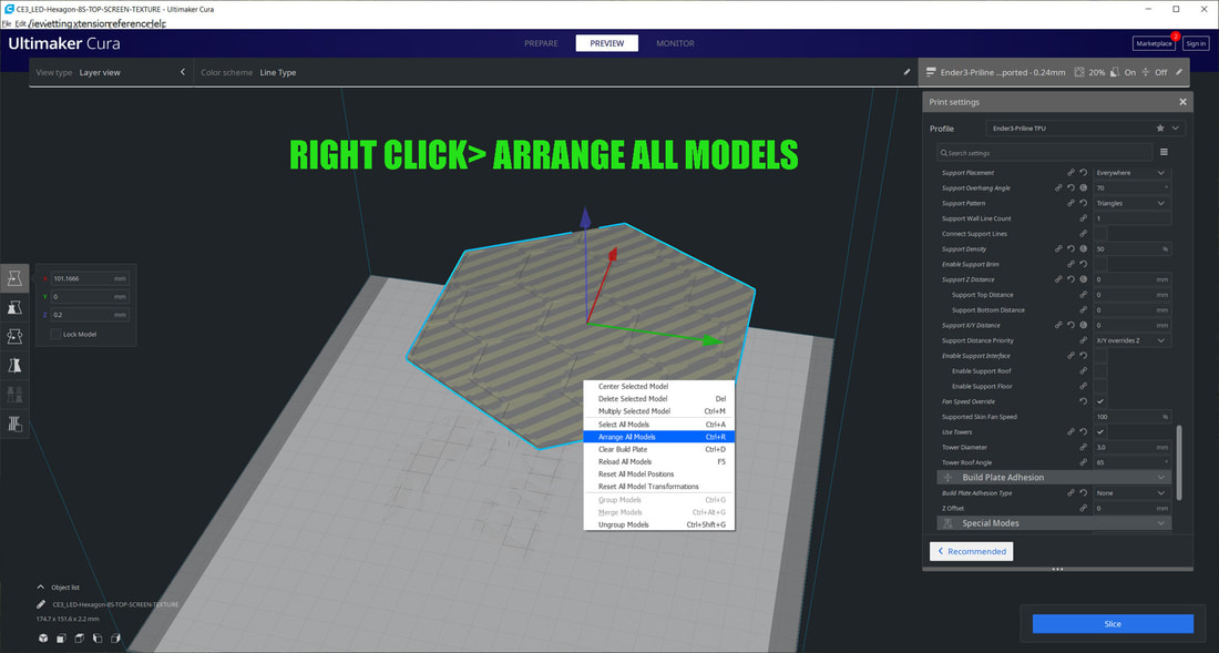
Step 3 - Arrange or Center the models
Now again right click and select "Arrange All Models". This should center the model on the printer bed.
Step 4 - Slice the model (first test slice), and preview
Slice the model to test and verify it looks correct using the "Preview" button. Note the following settings under "Supports":
Quality
Layer Height (0.2mm)
Initial Layer Height (0.2mm)
Supports
Generate Support (yes)
Support Structure (Normal)
Support Placement (everywhere)
Support Pattern (Triangles) - this is just what I chose
Support Wall Line Count (2)
Enable Support Brim (no)
Support Z Distance (0mm)
Support X/Y Distance (0mm)
Enable Support Interface (off)
Support Density (50%)
The Support Density and Support Pattern can be modified for different effects.
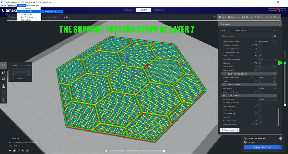
If it looks good, move the layer preview slider on the right side up and down to see where the support pattern stops and the outer frame is printed. On my model below, this is at layer 7. That is layer 6 is the last layer which prints as support. Layer 7 is printing only the frames for the inner hexagons, and these will continue to the final layer from this layer, up.
Quality
Layer Height (0.2mm)
Initial Layer Height (0.2mm)
Supports
Generate Support (yes)
Support Structure (Normal)
Support Placement (everywhere)
Support Pattern (Triangles) - this is just what I chose
Support Wall Line Count (2)
Enable Support Brim (no)
Support Z Distance (0mm)
Support X/Y Distance (0mm)
Enable Support Interface (off)
Support Density (50%)
The Support Density and Support Pattern can be modified for different effects.
If it looks good, move the layer preview slider on the right side up and down to see where the support pattern stops and the outer frame is printed. On my model below, this is at layer 7. That is layer 6 is the last layer which prints as support. Layer 7 is printing only the frames for the inner hexagons, and these will continue to the final layer from this layer, up.
This step is to have a color change between the white screens and a top layer of the frames which outline the hexagons (printed in gray in the top picture). To do a filament change you can use the "Post Processing" extension in Cura. From the top bar menus select Extensions > Post Processing > Modify G-Code. That will bring up a menu called "Post Processing Scripts". From here, select "Add a Script" and then select "Filament Change".
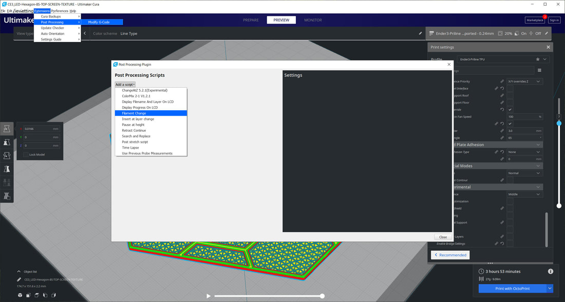
Step 6 - Filament change options
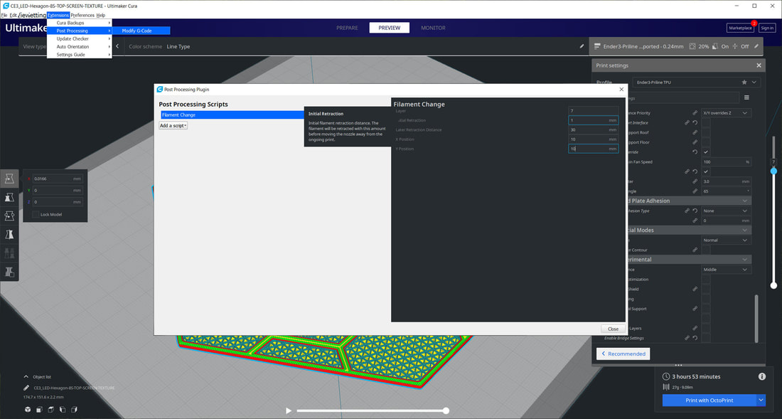
In the "Filament Change" script, I used the following settings (you may need to adjust for your printer since things like Initial retraction and Later Retraction will be depending on if you use a direct drive or Bowden setup). I use a Titan Aero direct drive so my setting for retractions will be much less than on a Bowden setup. You may want to test a filament change with a simple part before diving into a longer print, since getting the retraction wrong can result in blobs on the print. The reason it will change filaments at layer 7 is because that is the first layer I want printed in Gray. I had the X and Y positions set as 10mm simply to avoid a hard stop when the printer moves the nozzle to the park position.
Layer (7)
Initial Retraction (1mm)
Later Retraction Distance (30mm)
X Position (10mm)
Y Position (10mm)
Layer (7)
Initial Retraction (1mm)
Later Retraction Distance (30mm)
X Position (10mm)
Y Position (10mm)
Once everything is good, select close and then slice and preview again. If all looks good then it is ready to print.When you do the filament change, be careful not to bump the printer while swapping the filaments, which can cause a layer shift.
 RSS Feed
