I'm working on a re-design of my small Stanley solder fume extractor and it will use some new parts. The key component that made me decide to re-visit the original design was a board that integrates the USB Lipo charging and battery management, along with a boost circuit to raise the output to as much as 12v. In the prior design, much of the wire clutter in the case was due to the wires needed to connect two boards which handled this independently. Additionally the old design failed so it was time for a change. I am also adding a larger fan which will help with the biggest problem with the old design, and the reason I never posted it - it was not powerful enough.
Parts list:
Testing:
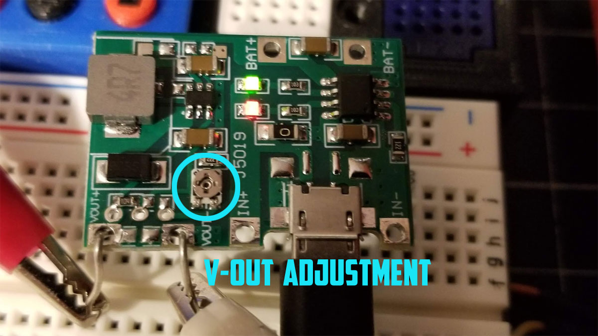
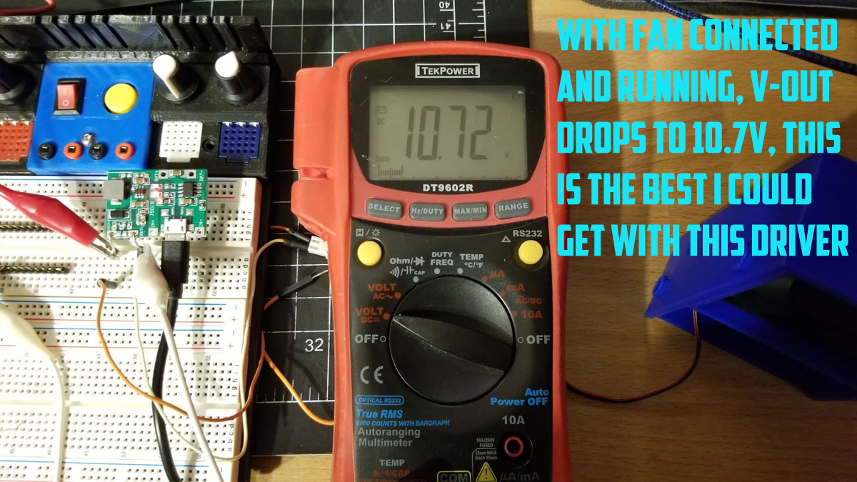
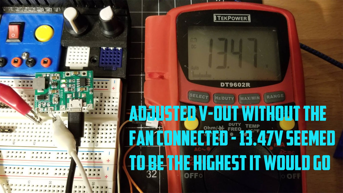
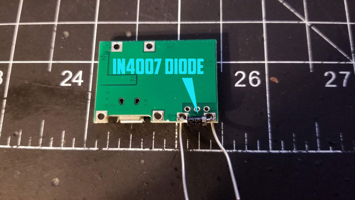
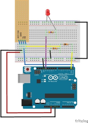
So the point of this is to see if the board can power the fan sufficiently or not. The problem is that the boost driver tops out around 12V so it will not be as efficient and it may not supply enough current. What I found was that although the voltage did drop to 10V when I had the fan on, it did seem to put out maybe 80% of the output of the fan when it was fully powered off my bench supply. It seems like it will work. I also had to adjust the board v out since by default it is set around 5v, this is done using a small potentiometer while the fan was running. I turned it up as high as I could get it to go when connected to a USB power supply (I will have to repeat this test with the battery and see if it will work. I found that I needed around 13.47V (without the fan) or 10.7V when it was loaded with the fan running. With the fan on, it pulled 0.126A (powered from the UBS). I also have a IN4007 diode connected across the V-out connections as shown, this acts as a flyback diode to help protect the board when the fan is turned off and the current reverses momentarily (note that I later found this was not needed by testing for a spike using a scope, I left this diode out in the final design).
One issue with this fan is that it squeals a bit when it starts up running from the USB board, though that does not happen when it starts using the bench supply. I didn't however notice this squeal when the final assembly was done, and the fan was turned on, not sure why that is but I will take it.
Below are some pics of the testing setup:
Parts list:
- 60x25mm 12v fan
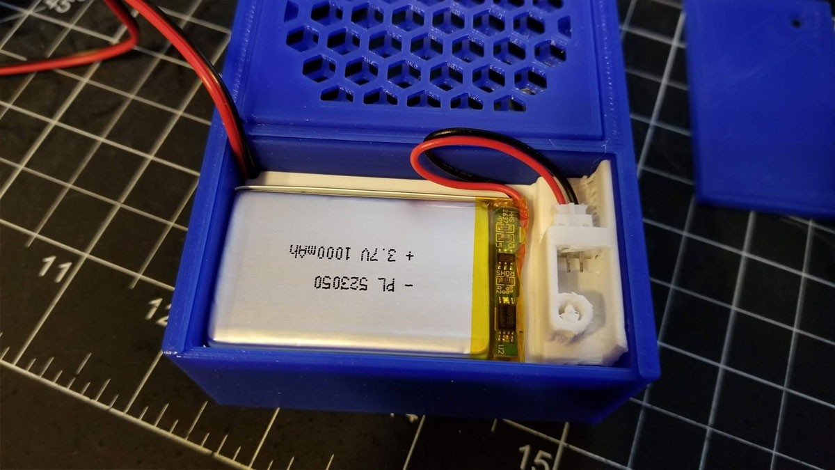
- 1000mAh Lipo 523050 Battery
- USB Lithium battery charging (TP4056) and boost module
- 1N4007 diode (I later found this is not needed since there was no voltage spike seen when shutting off my brushless fan)
- USB power supply
- small screwdriver for adjusting the output voltage on the board
Testing:
So the point of this is to see if the board can power the fan sufficiently or not. The problem is that the boost driver tops out around 12V so it will not be as efficient and it may not supply enough current. What I found was that although the voltage did drop to 10V when I had the fan on, it did seem to put out maybe 80% of the output of the fan when it was fully powered off my bench supply. It seems like it will work. I also had to adjust the board v out since by default it is set around 5v, this is done using a small potentiometer while the fan was running. I turned it up as high as I could get it to go when connected to a USB power supply (I will have to repeat this test with the battery and see if it will work. I found that I needed around 13.47V (without the fan) or 10.7V when it was loaded with the fan running. With the fan on, it pulled 0.126A (powered from the UBS). I also have a IN4007 diode connected across the V-out connections as shown, this acts as a flyback diode to help protect the board when the fan is turned off and the current reverses momentarily (note that I later found this was not needed by testing for a spike using a scope, I left this diode out in the final design).
One issue with this fan is that it squeals a bit when it starts up running from the USB board, though that does not happen when it starts using the bench supply. I didn't however notice this squeal when the final assembly was done, and the fan was turned on, not sure why that is but I will take it.
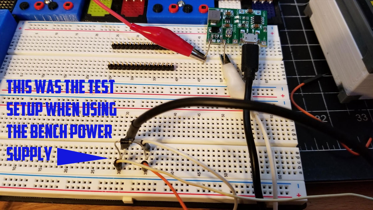
Below are some pics of the testing setup:

For the sake of comparison, I also tested with my bench supply. I was interested in how well the fan worked when supplied as much current as it wanted, and noticed a difference but it was not huge. The fan pulled about 0.13A @ 12V. I also used the flyback diode in this set up (again note the diode is not needed and was removed from the final design).


I tested this again using only the battery which was fully charged using the board shown above. I found that I had to turn the potentiometer down just a touch from where it was when running on the USB input, but it was still able to reliably deliver 10.1V (didn't check the amps this time but the fan seemed to have a good amount of suction).
I tested the suction using a candle and a toothpick to generate some smoke and was able to hold it about 5" away and get the fumes drawn into the fan. It was usable for about 50 minutes off the fully charged battery (which by then measured 3.41V), and dropped out to being barely on at 53 minutes, at which point the battery was at 3.40V. I did the test with the carbon filter in place, and so I think this may be the answer to the problems I had previously (larger fan and larger battery). One issue is that when used upright at least, there seems to be a sweet spot where fumes get sucked through the fan, but outside that area which may be 2" wide, it will start to go around the fan (but still gets sucked away). I think adding some folding shutters to the sides may help keep more of the fumes going through the fan than around it. The problem however is that this fan is crammed full of stuff and there is no room to add that (update - the final design incorporates a simple duct to help with this issue).
I also found a way to add a micro mini (low profile) fuse and fuse holder to this without changing much of the design. The fuse will be accessible from the front and shouldn't look too bad.

 RSS Feed
