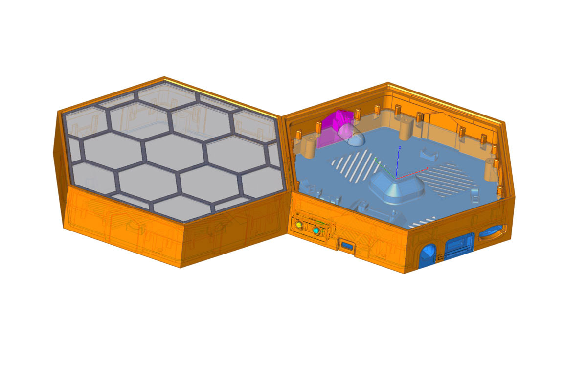
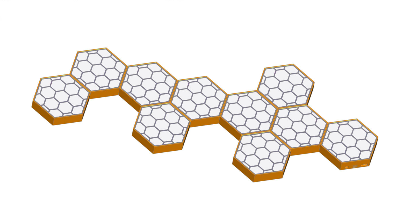
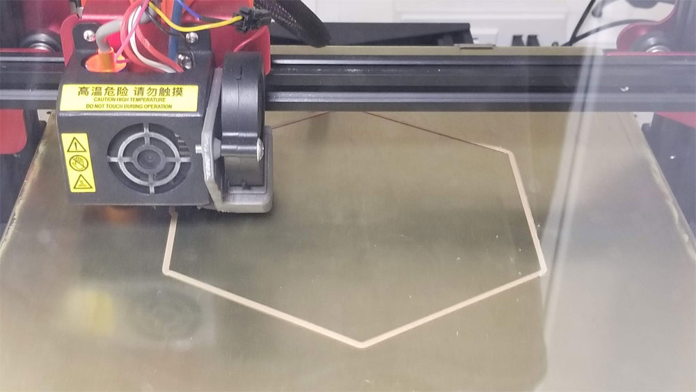
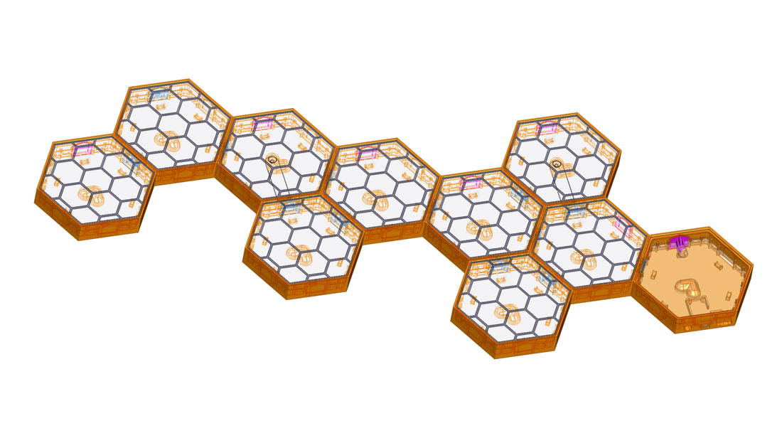
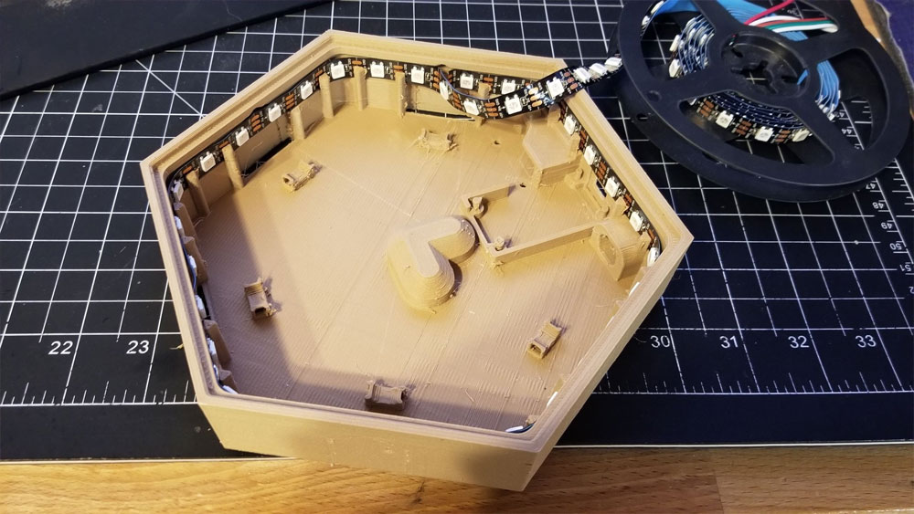
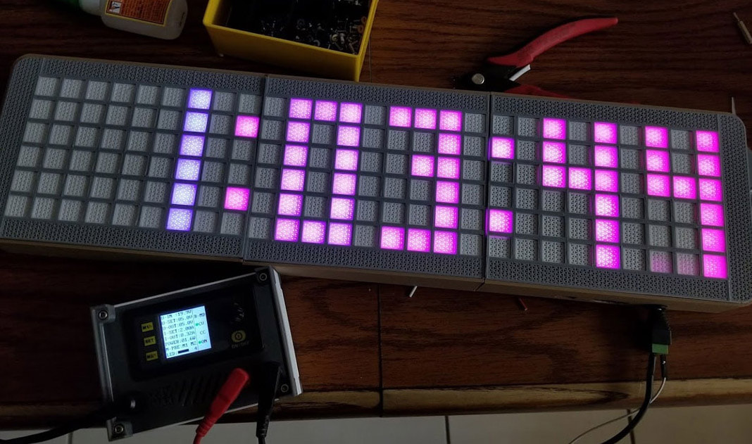
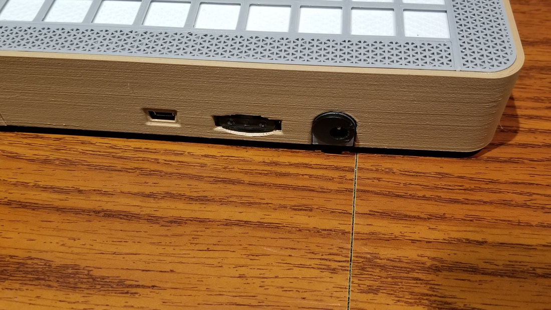
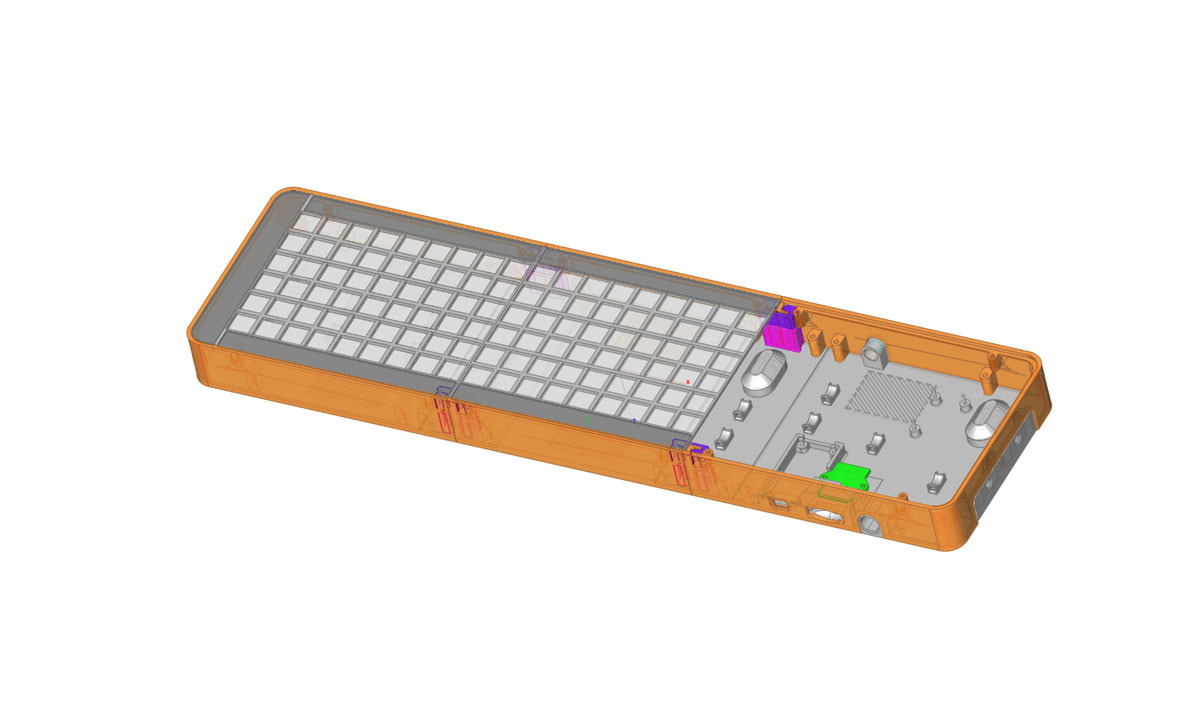
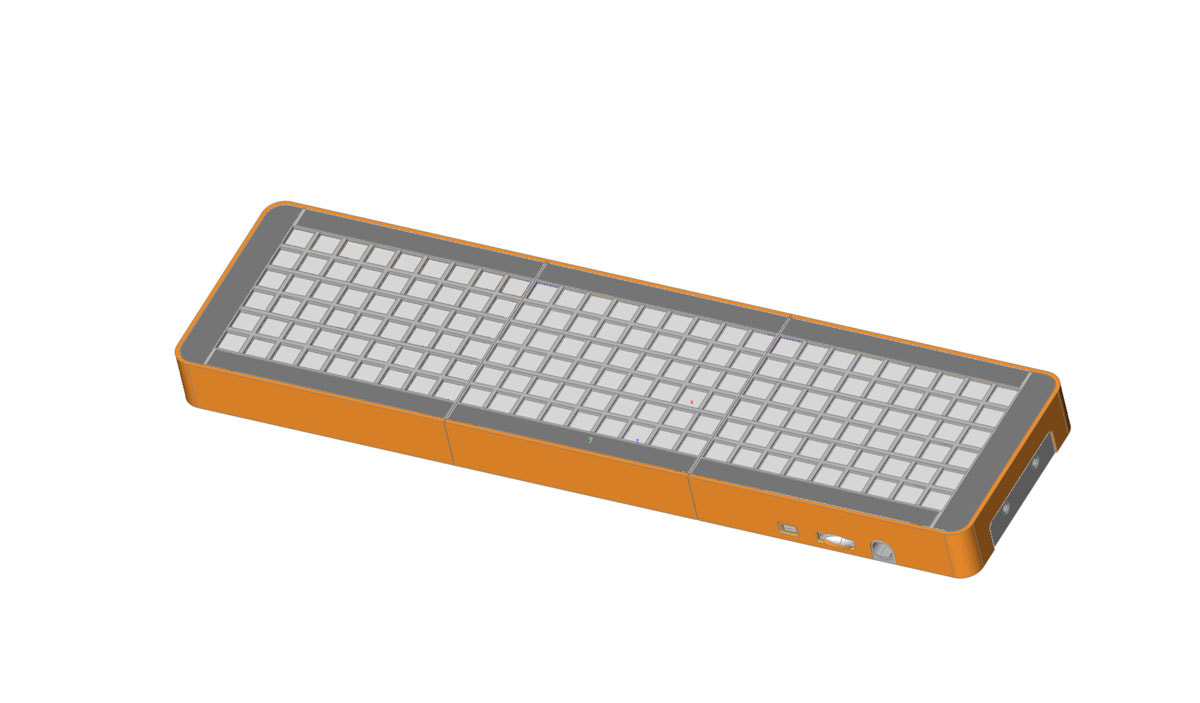
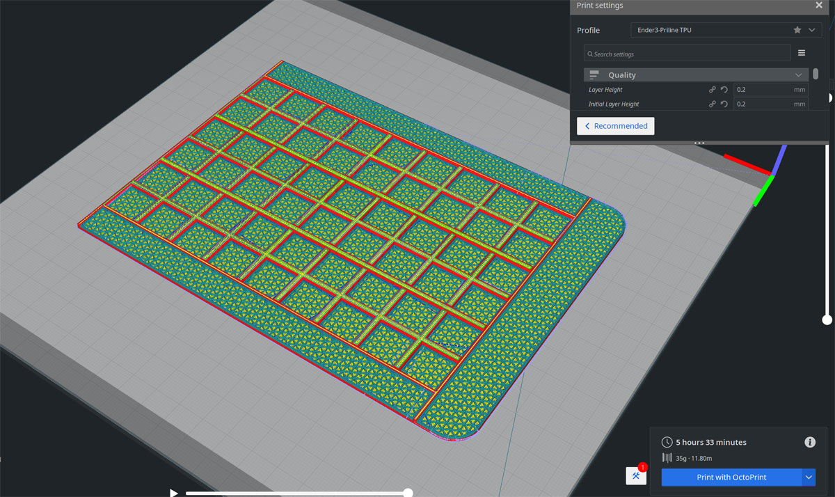
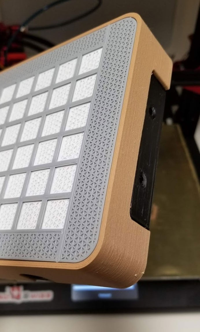
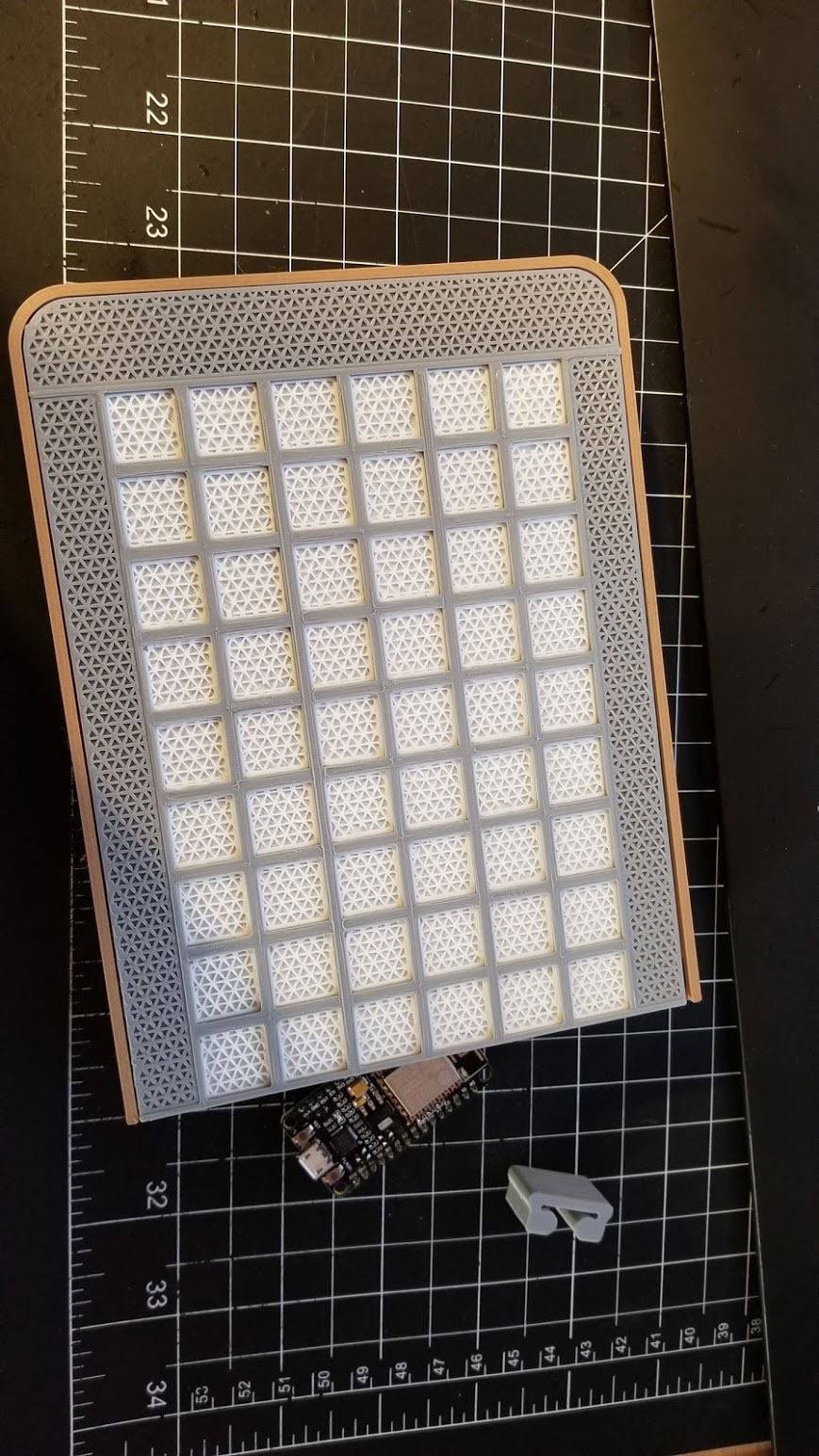
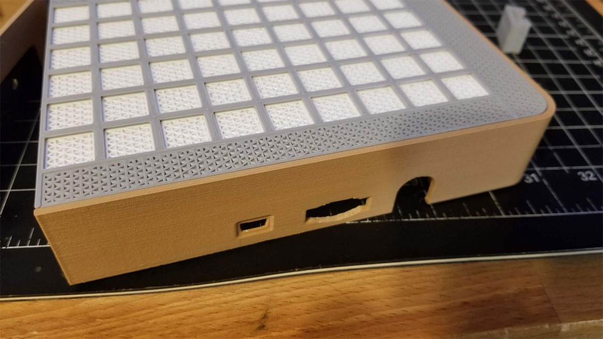
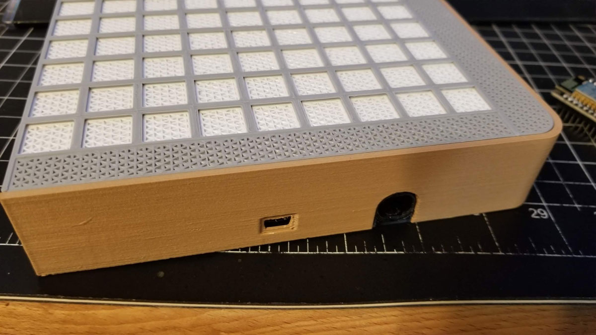
I've been updating and re-working the model for the Hex LED Panels for the past few days, and have tested most of the parts to make sure they fit. So far it's looking good, though I wasted several panels worth of wood PLA when I thought I was ready to start printing, only to decide I needed a couple if buttons or something added. Above is hopefully the last iteration, and although it looks like nothing much has changed, the model is almost completely redone. It has been split into a side and base (to conserve the more expensive wood PLA and make it simpler to work on), there is now a power switch, a couple buttons, and the electronics holders have all been tweaked and tested. I expect that each panel will be a 20 hour print on my printers, but since they are now split into several parts I can run my two printers at a time and knock them out quicker. I will probably be able to bring that time down with some slicer settings too, though no by much. Most of these Hex LED panel designs seem to be built for quick printing, so it was a bit of a shock to realize what I had gotten myself into, for yet another printing project. But I'm hopeful that these will end up looking pretty good, with no light leakage in the frames and sturdy construction, as well as being fully printable.
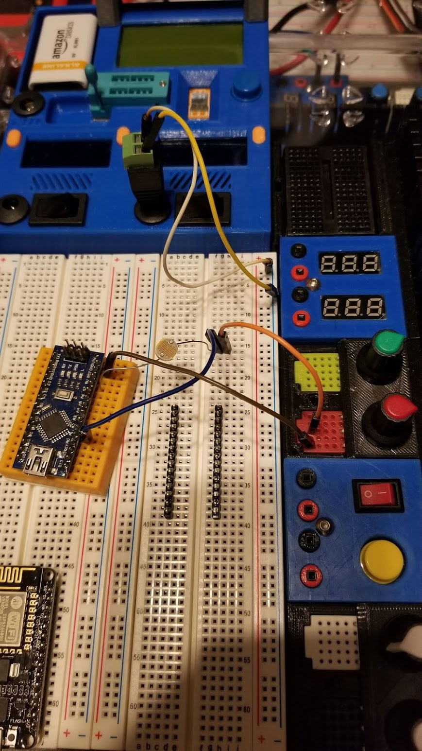
The code side is gonna be the slow part for me, but I have been looking at blynk.io as a jumping off point to learn how to get an app to work with these. Blynk.io looks really cool, though I haven't had time to scratch the surface and try it out yet. To be clear though, I'm no coder, and I'm not making any promises regarding working on the code for this, in fact I will probably use the Nerdforge code and call it a day. This is however the kind of project I have been looking for, where I can work on something that is actually interesting to me, and improve my novice Arduino skills.
The code side is gonna be the slow part for me, but I have been looking at blynk.io as a jumping off point to learn how to get an app to work with these. Blynk.io looks really cool, though I haven't had time to scratch the surface and try it out yet. To be clear though, I'm no coder, and I'm not making any promises regarding working on the code for this, in fact I will probably use the Nerdforge code and call it a day. This is however the kind of project I have been looking for, where I can work on something that is actually interesting to me, and improve my novice Arduino skills.


 RSS Feed
