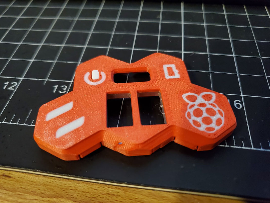
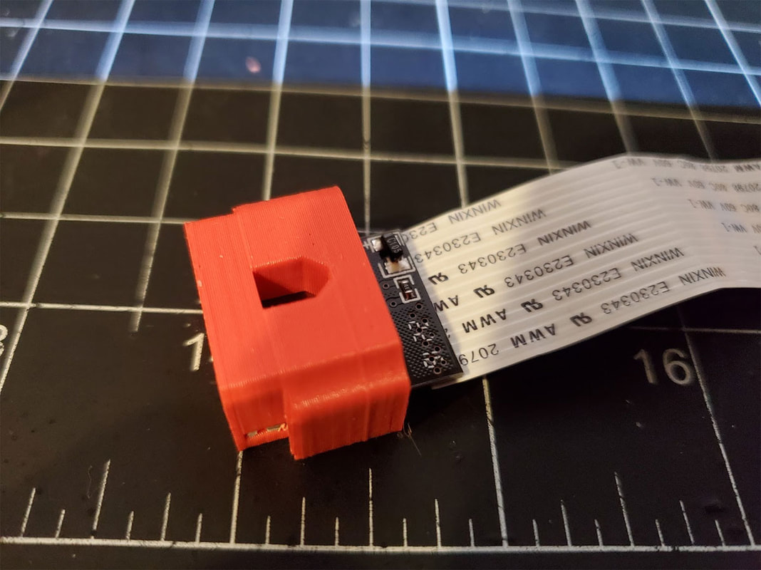
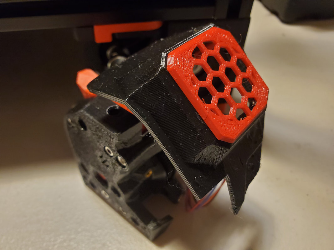
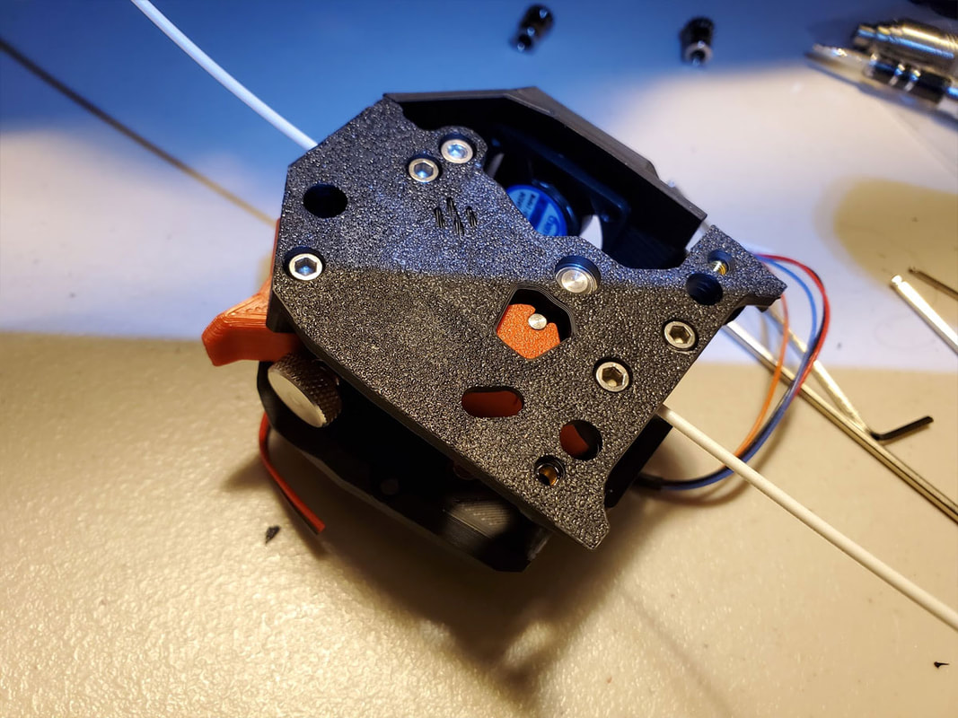
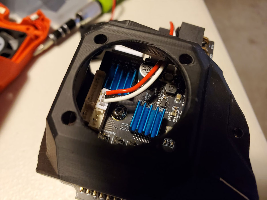
It has been a while since I worked on the Pi Panel Skirt for my Voron printer build, but I'm closing in on when I may actually need to use it. The design has not changed much on the outside, since I originally posted about it back in October, but there have been quite a few changes under the hood recently. I printed a first version and decided that if I changed the SD holder to a design that removes the stock plastic shell similar to this, I could get some more area to add a shutdown button for the Pi (safe shutdown button). The pics below are before I re-worked it (yet again). I know, the prints are not good, since I was using PETG which I did not dial in well, and a 0.6mm nozzle, where I should be using PLA and a 0.4mm nozzle due to the fine details. It's just a prototype though, and it did prove the fit was good on some things and not so good on others. In any case, it's moving along and I have some PLA on the way which will hopefully match the rest of the red on my printer, which is Sunlu ABS in red (which is a muted red, and I guess has a matte finish on the stuff they sell in China).
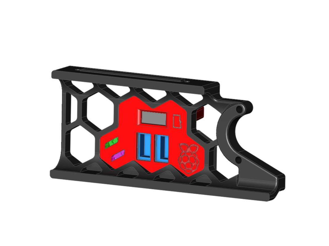
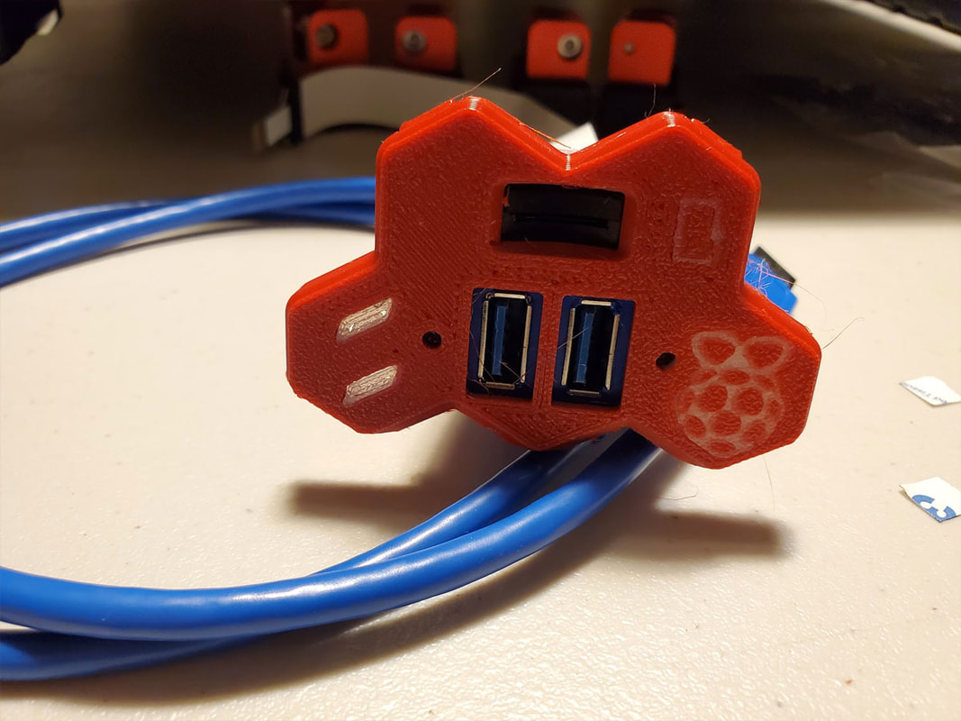
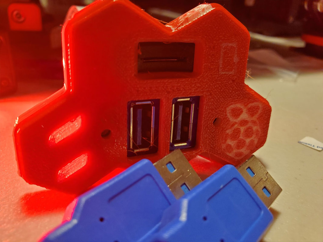


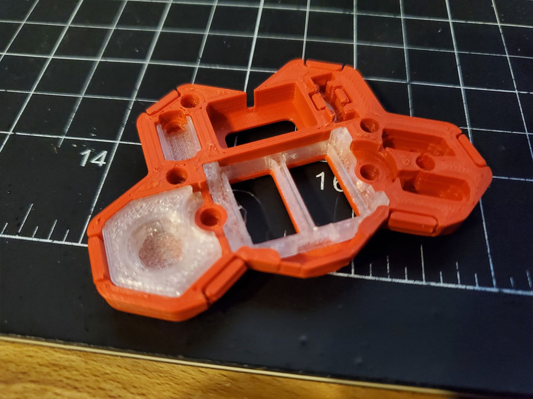
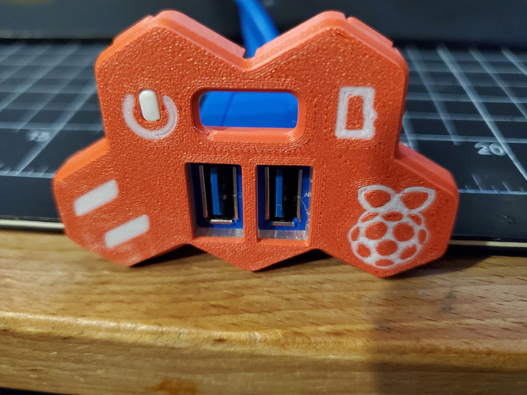
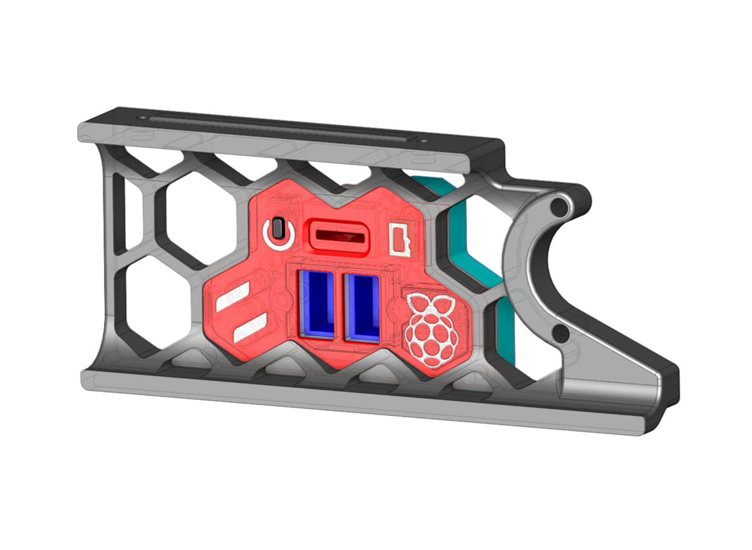
This is the newest version, which is still needing to be printed. In this version, there are two general purpose LEDs on the left, a disk activity LED for the Pi (shaped like an SD card) and the raspberry also will have a LED backlight for the Pi power status. The power button is the tic-tac shaped thing in black which I sort'a designed so it would look like the power/reset symbol. There is also a LED ring light for the USB ports. I am not sure yet if the design for the SD port will change, since I may go with something simper if I need to add a black masking layer in the print. I have a feeling there will be some bleed through unless I switch to black after a few layers. There is a wire management cover on the back which will hopefully keep the chaos under some degree of control for all the LEDs and switch wires. I plan to route then back along the USB cables to the Pi. I also plan a version for folks that want to add a 0.6mm hexagonal grill to the skirt.
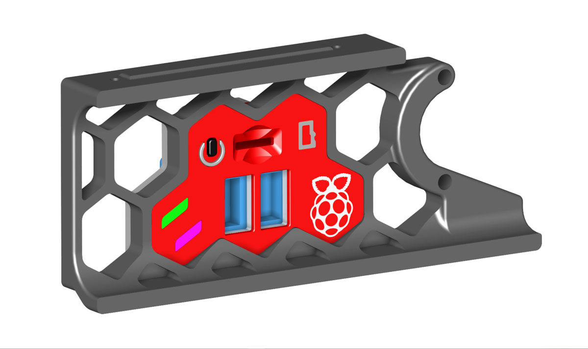
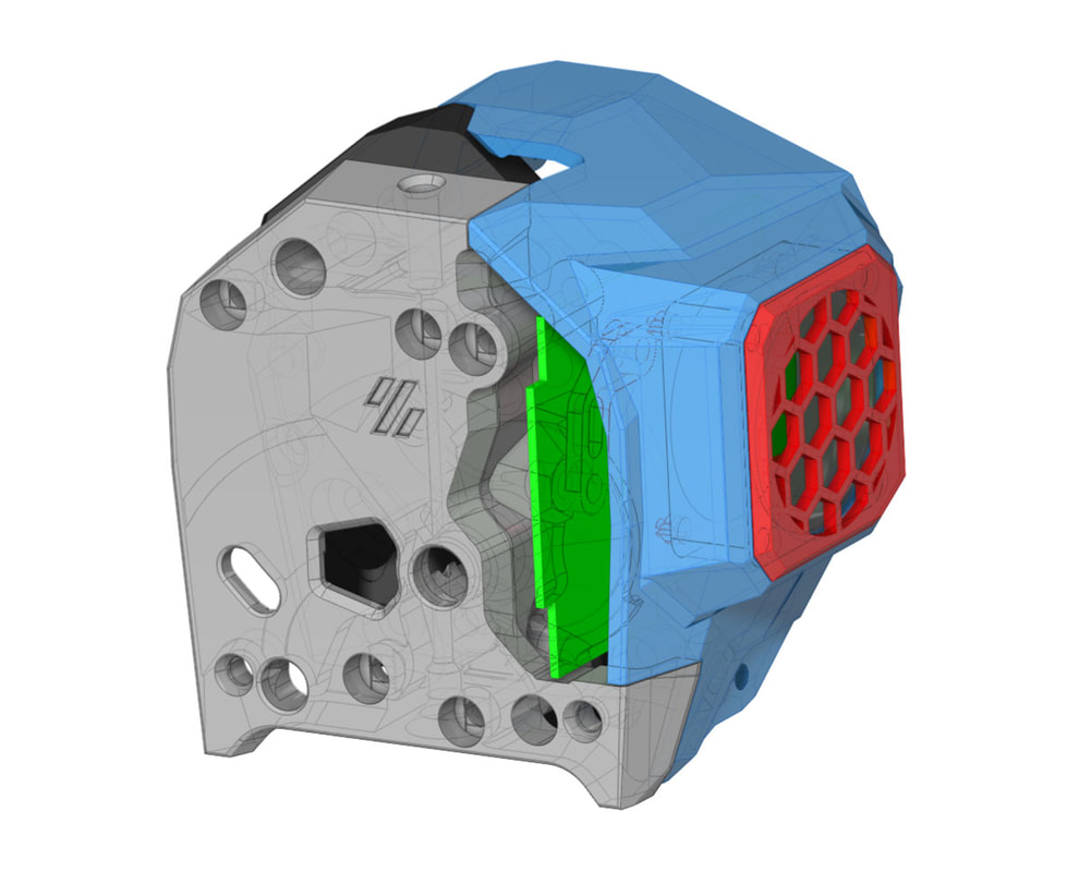
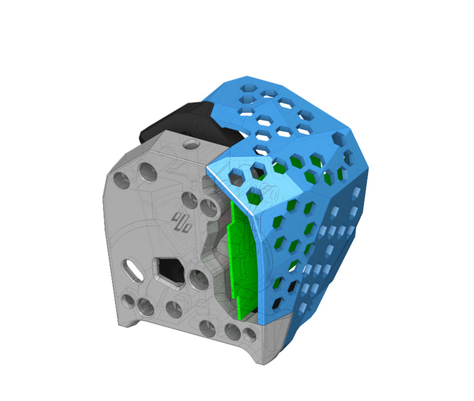
Update 4/29/2023: After printing the above model, I decided that some changes were needed. Most of the work required (of which there was quite a bit), is below the surface, however some cosmetic changes were made as well. I dropped the inset power/reset symbol, and went with a simpler and cleaner looking printed inset layer for that, and the same for the two function LED's on the left side. The SD holder is also updated to print easier, and I think it looks cleaner as well. Overall the design is much less cluttered and simplified. Below the surface, I made a few light diffusers for the Pi logo, using either Lilly pad LED or a WS2812B LED chip (which of course I now have to wait for). There were also a bunch of changes to the SD card holder, and the cable management cover.
The BOM so far is as follows:
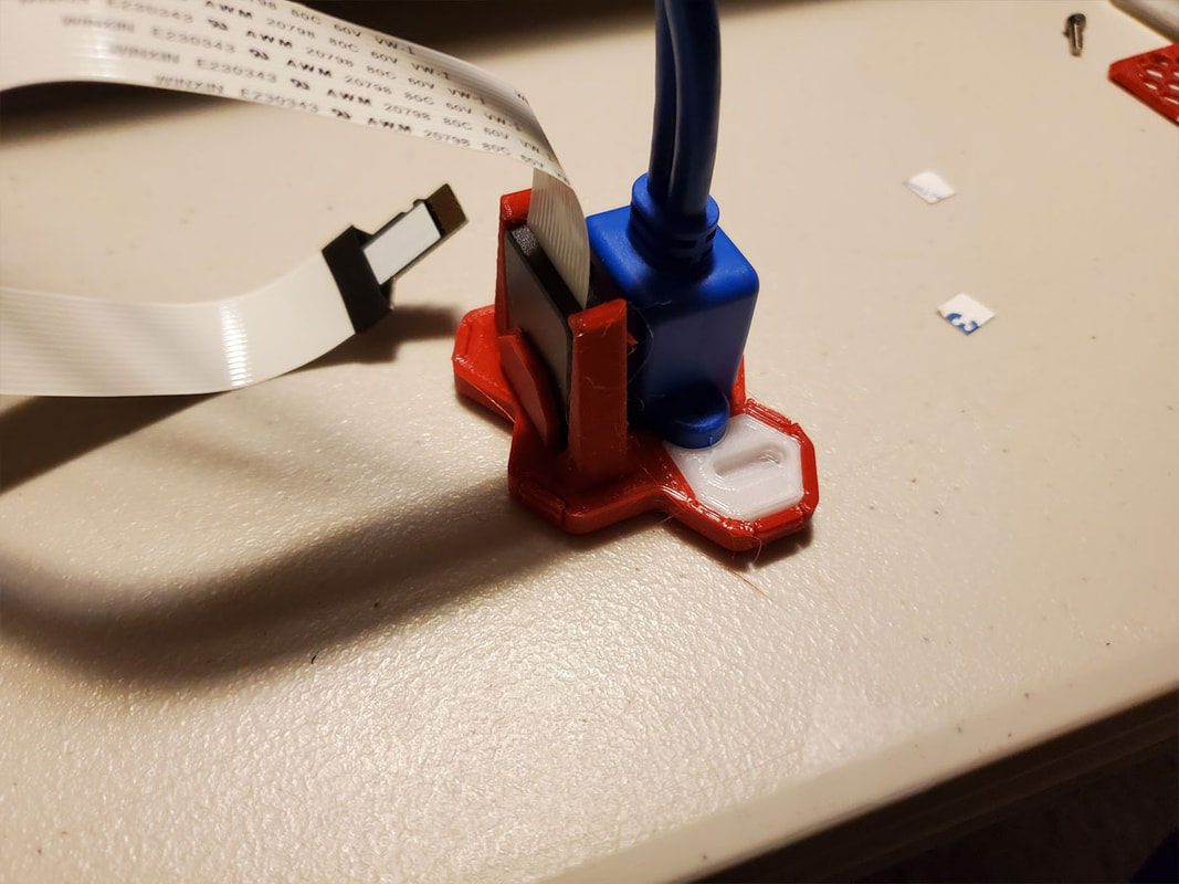
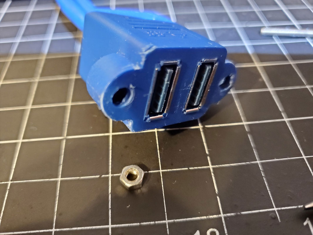
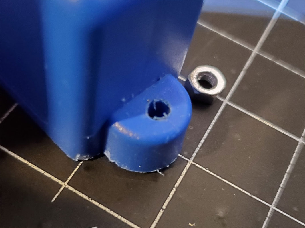
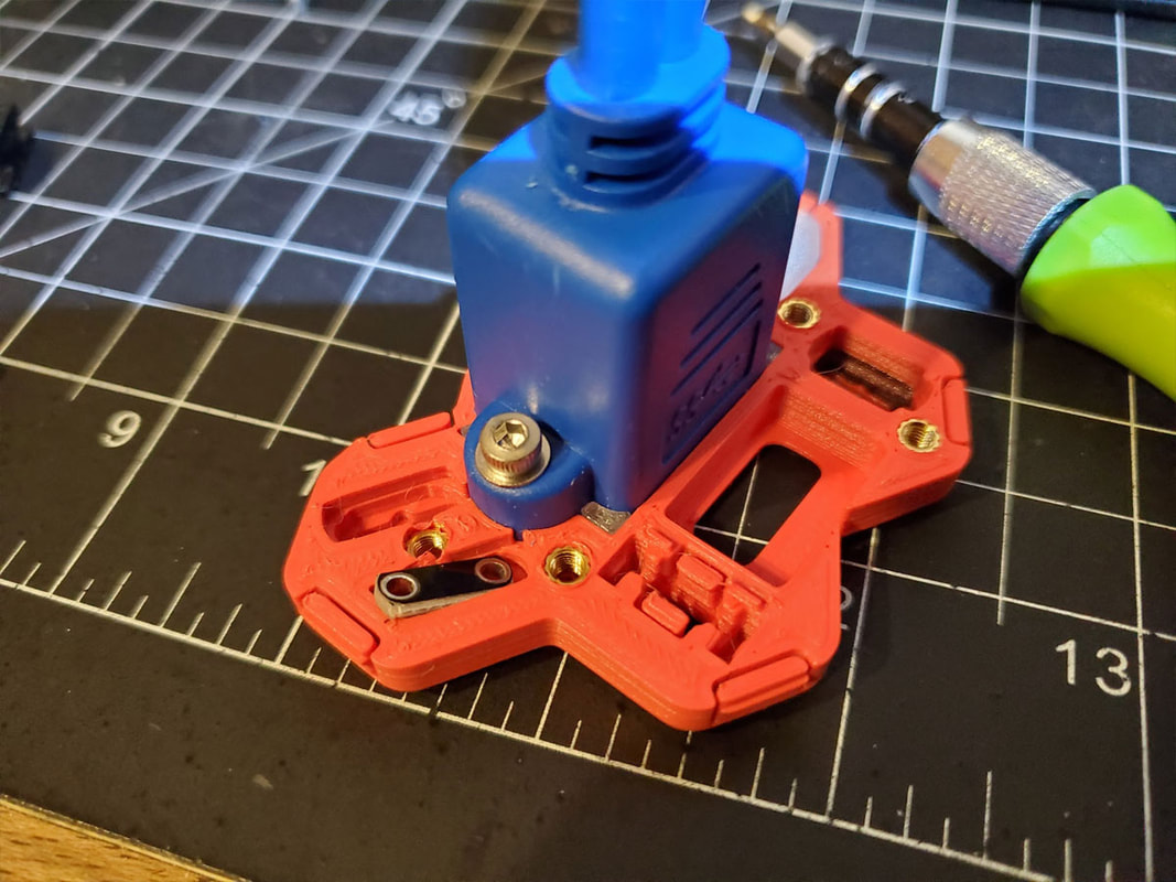
I'm still working on this and again waiting on the WS2812B, but that won't stop me from testing this with the LilyPad LED's. What will stop me from working on it, is... work. I will probably get back to this next week. So far though, the design looks to be going together as planned, and everything at least fits. Printing it will require a properly calibrated printer (esteps, flow and possibly horizontal expansion compensation, with dry filament). Although I designed in a good margin for fitting the small parts where possible, there is a lot crammed into a small space, so things will be tight. There is also a mild bit of hacking to extract the captive M3 nuts in the USB extension, and I leaned the hard way to drill them out from the back side and not the front, but they should come out without too much trouble. I plan to glue the USB extension in for some extra security, once everything else is in place.
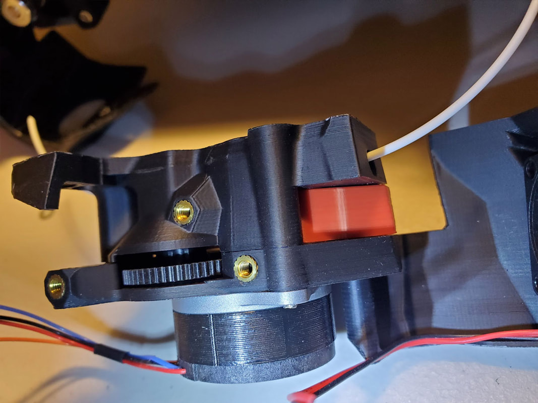
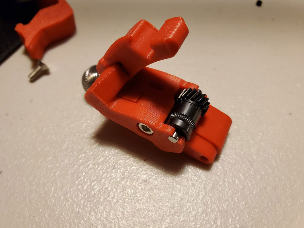
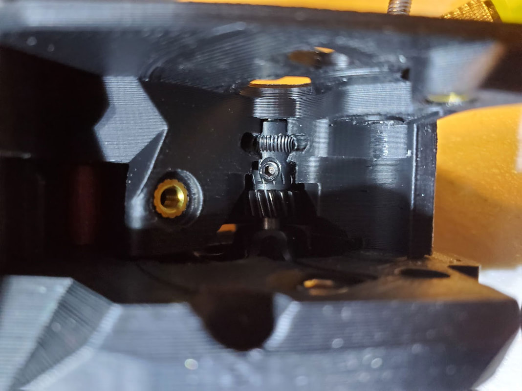
Some of the pics below are earlier prototypes, the later pics are close to the final version. This is not yet posted (I need to test it first).
The BOM so far is as follows:
- (qty 8) M3 4.2mm (dia) x 3mm Brass inserts.
- (qty 1) USB 3.0 dual panel mount extension (this is the side by side blue one which is available in 30 or 50cm lengths)
- (qty 1) 25cm MicroSD female to male extension
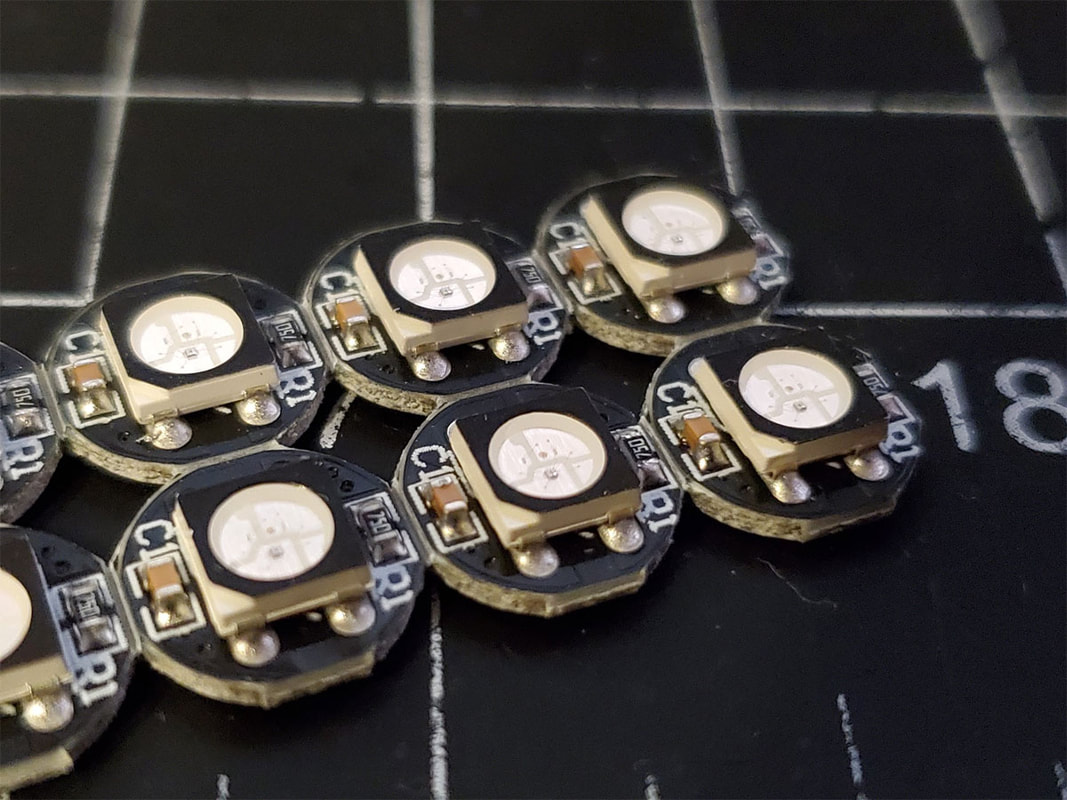
- (qty 4-5) LilyPad LED modules in multiple colors
- Wires and dupont female connectors and crimps
- (qty 1) Optional WS2812B LED chip
- Superglue Gel (I use Gorilla SuperGlue Gel which works really well)
- I may use an old floppy disk ribbon cable to keep the LED wires simple.
- 6x3.5x4mm Momentary Push Button Switches (I used the switches from this assortment).
- Black Sharpie (optional, but may help to mask out stray photons)
I'm still working on this and again waiting on the WS2812B, but that won't stop me from testing this with the LilyPad LED's. What will stop me from working on it, is... work. I will probably get back to this next week. So far though, the design looks to be going together as planned, and everything at least fits. Printing it will require a properly calibrated printer (esteps, flow and possibly horizontal expansion compensation, with dry filament). Although I designed in a good margin for fitting the small parts where possible, there is a lot crammed into a small space, so things will be tight. There is also a mild bit of hacking to extract the captive M3 nuts in the USB extension, and I leaned the hard way to drill them out from the back side and not the front, but they should come out without too much trouble. I plan to glue the USB extension in for some extra security, once everything else is in place.
Some of the pics below are earlier prototypes, the later pics are close to the final version. This is not yet posted (I need to test it first).
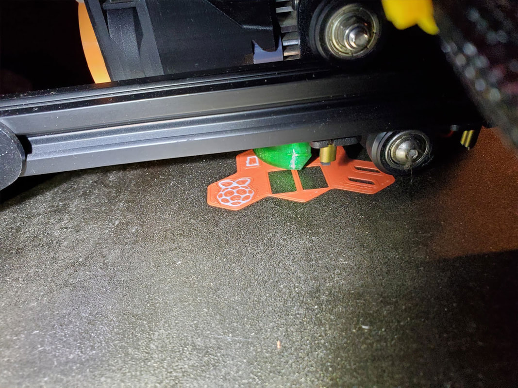

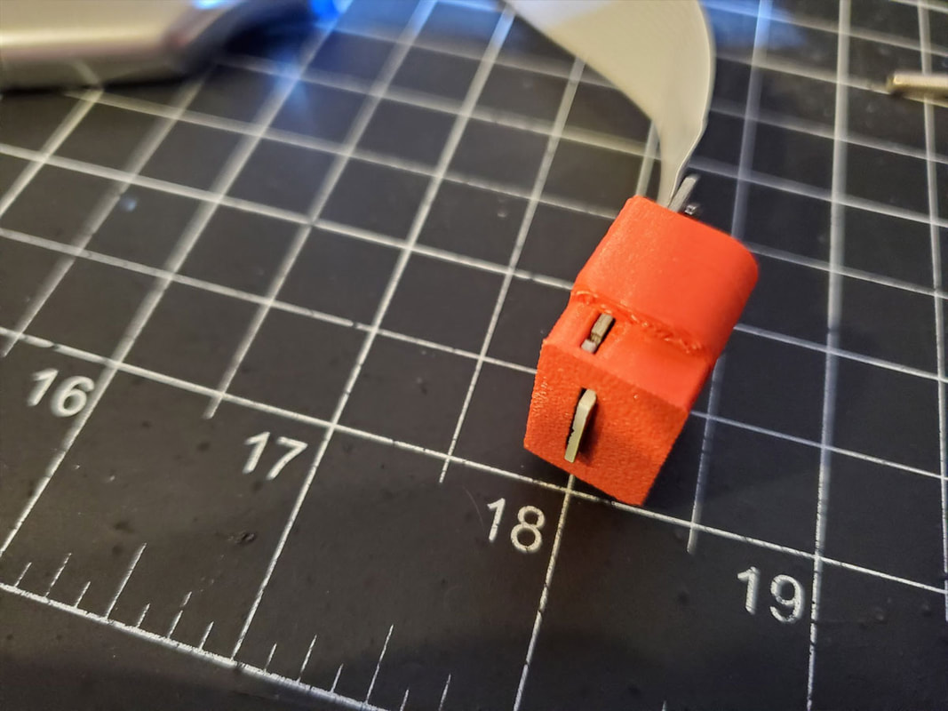
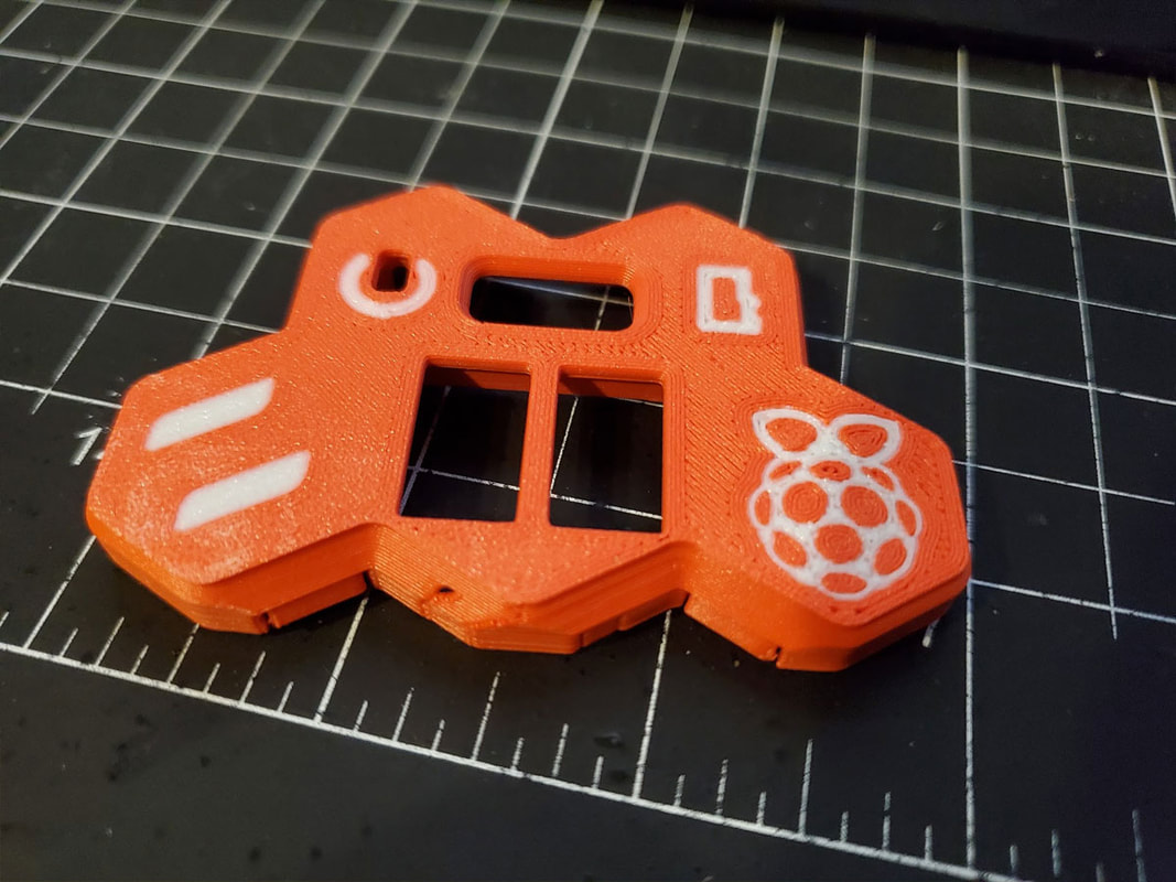


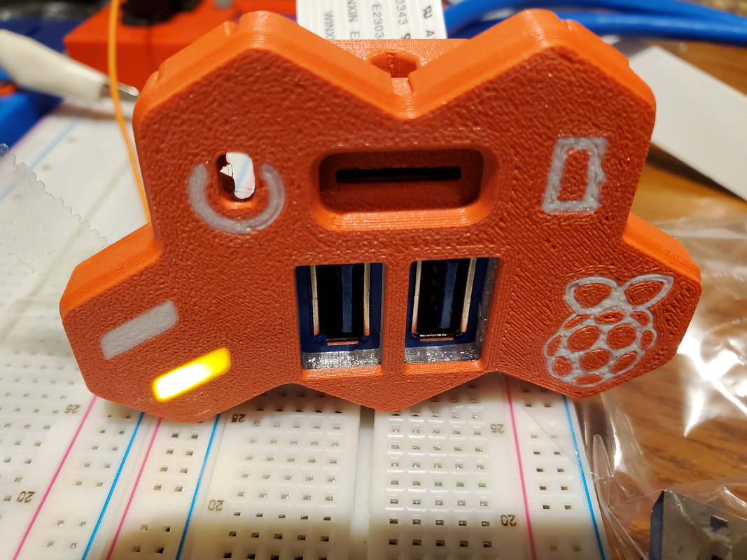
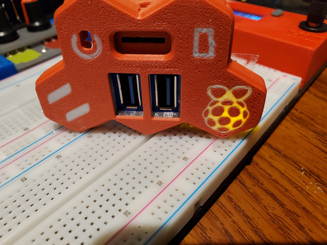
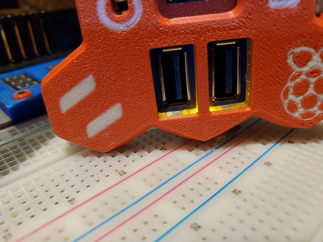
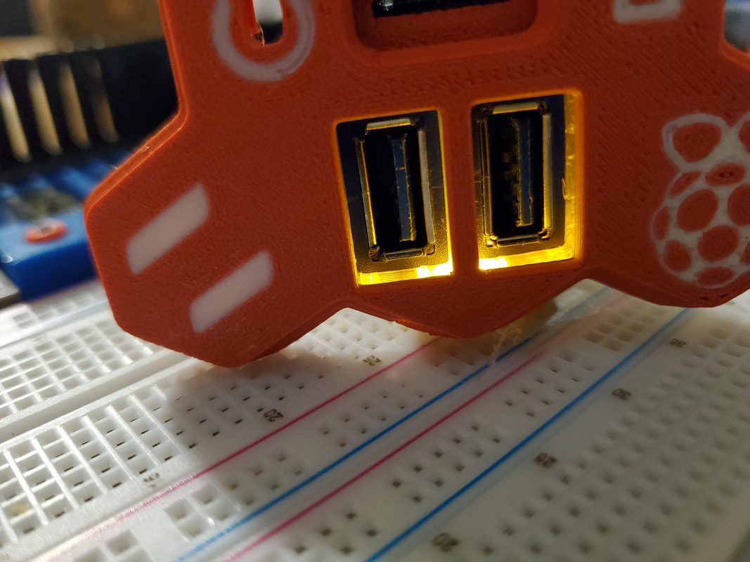
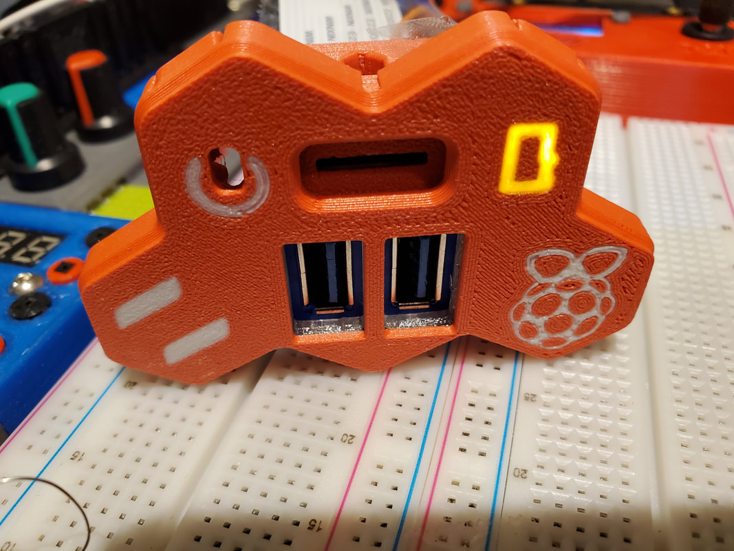
4/30/2023: This is probably all the progress I can show for a while, waiting on some WS2812B LED boards from AliExpress. The testing today did show a few issues which I think have been resolved. The first is that the Pi logo will not be adequately illuminated by one Lilypad LED, but the WS2712B should have no problem with that. I went ahead though and made an insert to allow using two Lilypad LED's to light up the Pi Logo, which should be enough. I'm pretty happy with the way the rest of the lights will illuminate though. The pics below were done using an orange LED which was the only one I had handy (also waiting on some more Lilypad LED's in green). I'm not sure which colors I will use, and if maybe I should use one color (red or blue), or if I should try different colors. I'm also not sure which two functions will be mapped to the LEDs on the left side (which may determine their color).
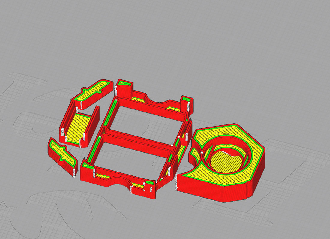
I also spent some time cleaning up and optimizing a wire management method for this part. I really hate to see wires everywhere, and so there will be a three part wire management module. The module will secure the LED's (which will also need to be glued in), give some space to manage the wires, and finally cover the whole mess up, while also adding some extra security to the USB ports.
I also spent some time cleaning up and optimizing a wire management method for this part. I really hate to see wires everywhere, and so there will be a three part wire management module. The module will secure the LED's (which will also need to be glued in), give some space to manage the wires, and finally cover the whole mess up, while also adding some extra security to the USB ports.

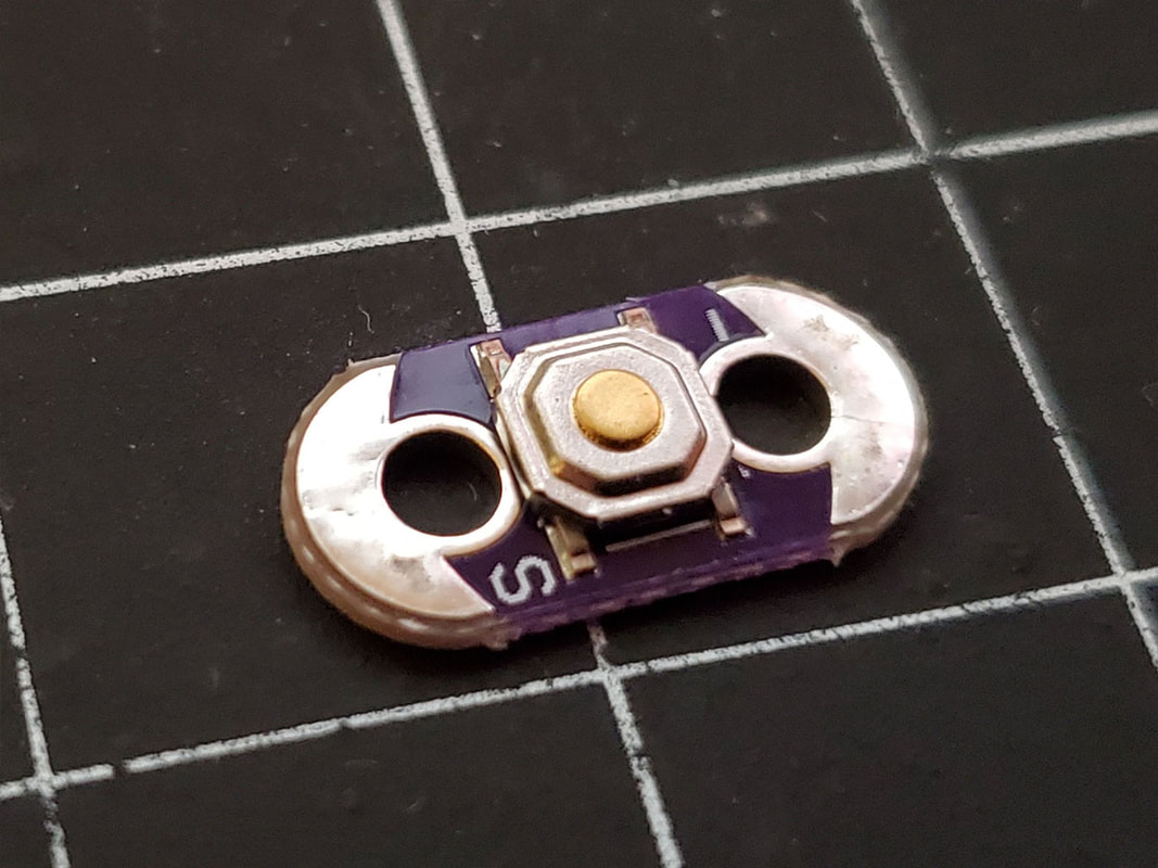
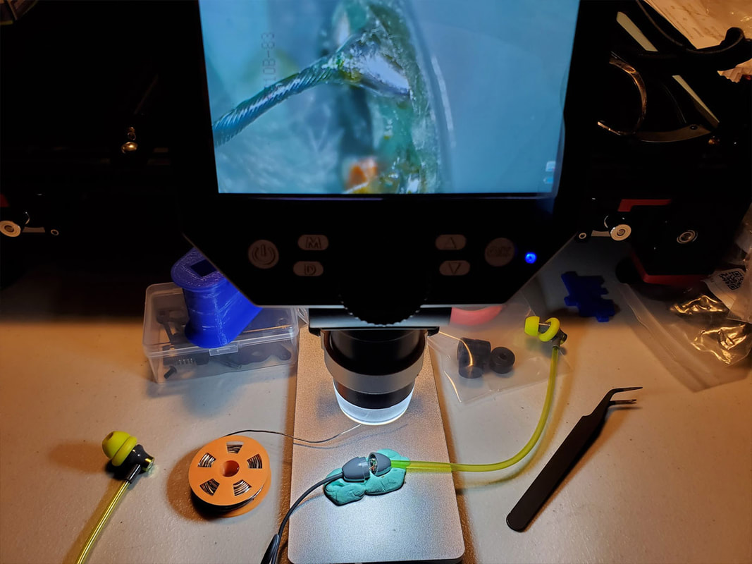
Update 5/18/2023: I recieved the WS2812B LEDs and also some LilyPad momentary switches, which I think would work better than the tiny switch I am using in the current design. The LilyPad switches are more, but I think for reliability and being easier to assemble, they are probably worth it.
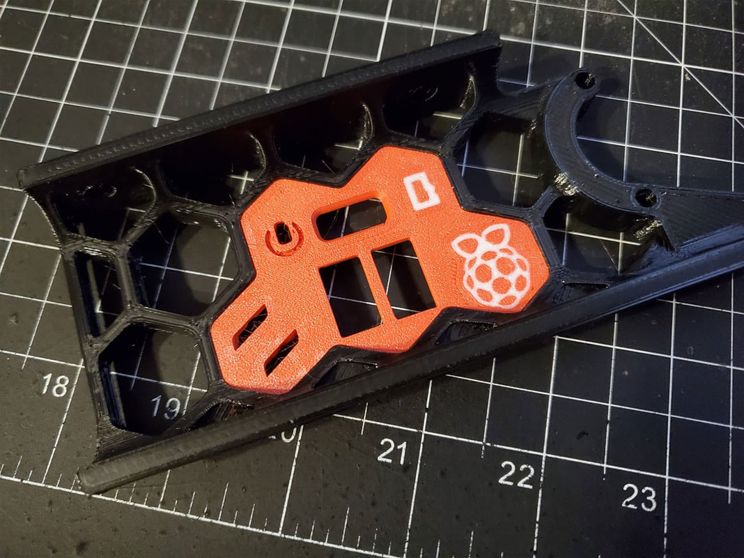
Update 5/20/2023: The updated design with the LilyPad momentary switch is ready to have a prototype printed to test. My printer is tied up at the moment though, with yet another part for the Voron. I was able to assemble some earlier prototype parts I previously printed (to test the fit only), and made some changes to the current model, which will help with assembly. The good news is that there were no show stoppers, and the assembly went pretty smoothly. I won't be using the test model though, since it is an earlier revision printed prior to changing to the LilyPad button.
Update 6/2/2023: I feel the design is probably done, however my printers have been tied up on other projects and there have been other life related issues going on so the Pi Panel has not yet been test printed. It is not forgotten though, I am gonna get it printed as soon as possible (but after the Voron Cable Management Duct Remix is completed since I need that to move my Voron build along).
Update 8/3/2023: I have not tested the design, but it has been way too long and so I posted the latest version (which I think will work). You can read about that here.


 RSS Feed
