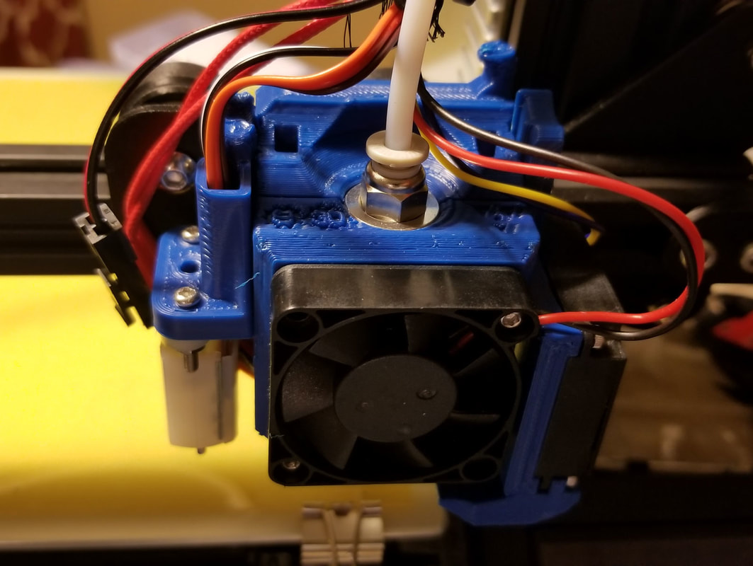
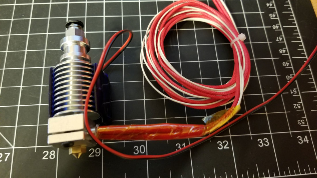
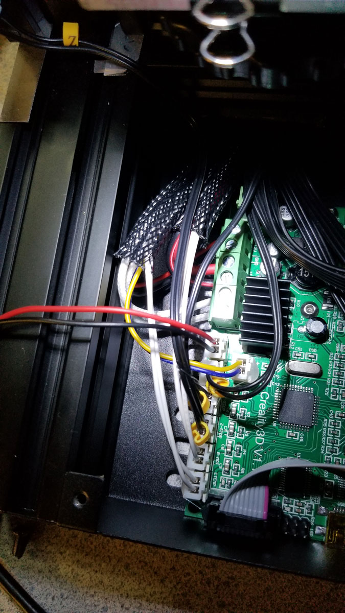
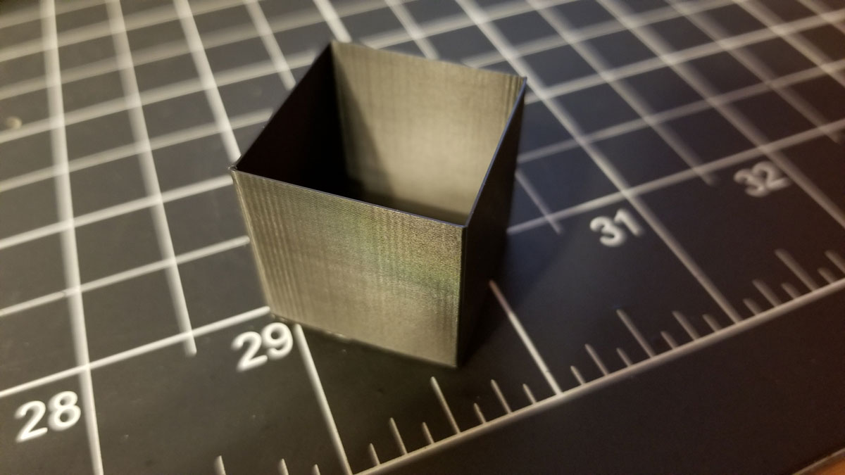
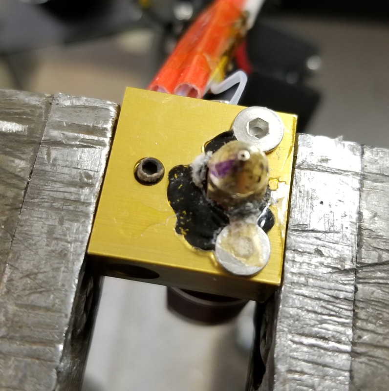
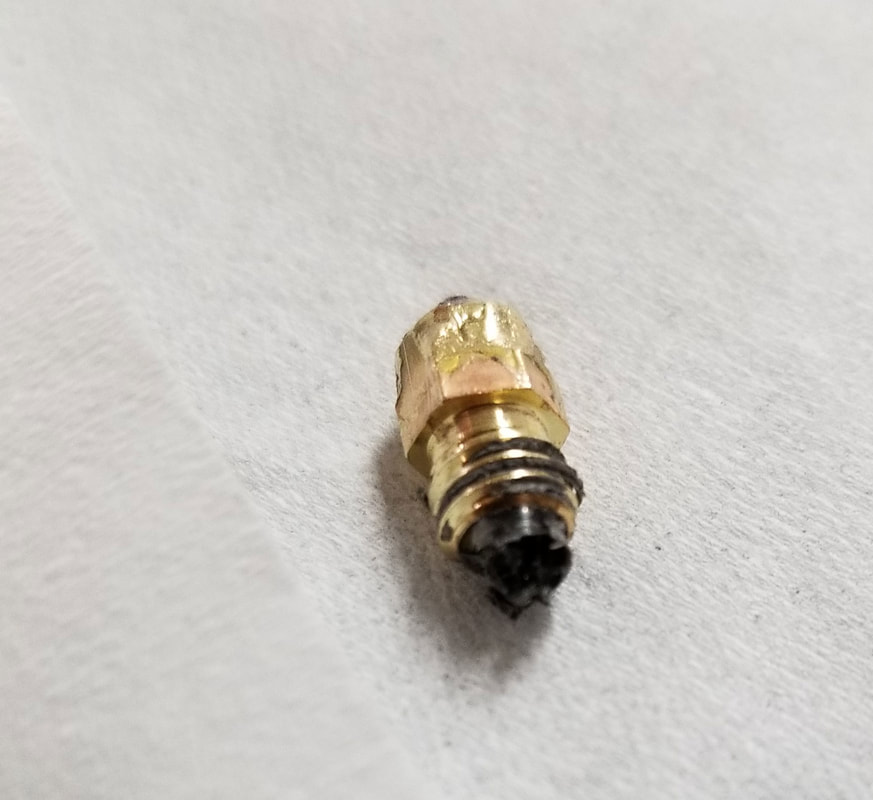
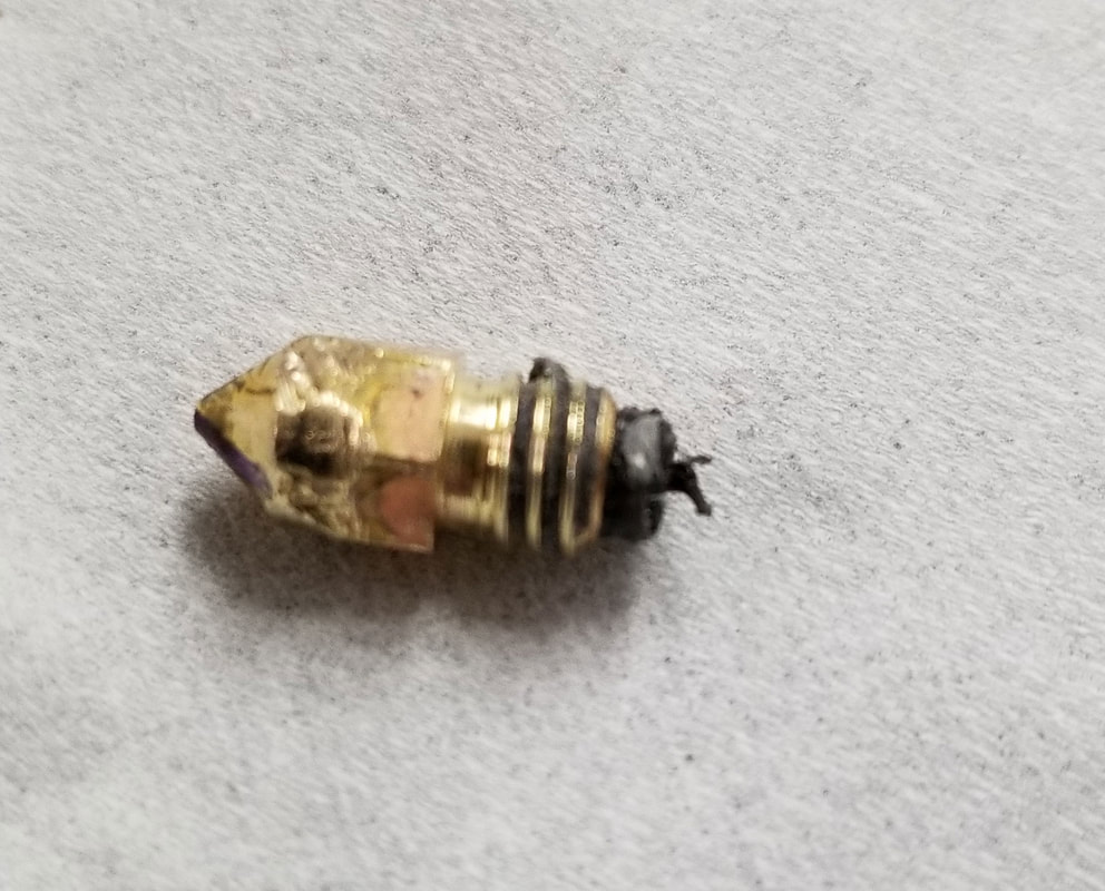
Seems like every time I get my hopes up that I may have a fix, something breaks. However I am getting closer. I swapped the V6 clone hot end with genuine E3D parts (except for the heatsink which is retained from the clone). The new Genuine E3D heatbreak looks better but not perfect, though I don't expect it to have any issues feeding. I bought the E3D V6 heat block simply because it included the cartridge type thermistor which I expect will be hassle free and it also has some neat silicone socks included. There are some additional marlin configs needed but they are well documented here.
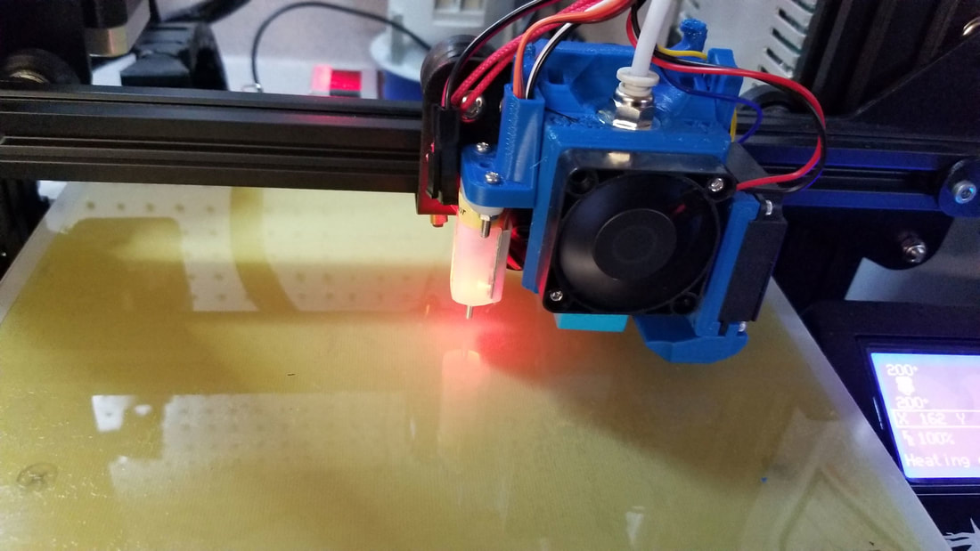
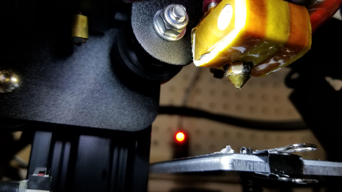
I also added a 3D Touch probe, because when I am just trying to get the damn thing working, why not double down on the possible points of failure (but I had the printer and wiring loom already in a minor state of disassembly). So whats the problem now? I lost the damn nozzle (doh). So now I'm waiting for a pack of those, but otherwise the printer is back together and ready to hopefully rock and roll.
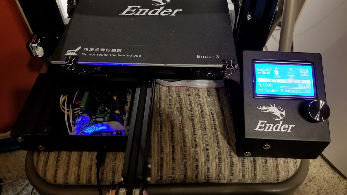
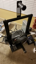
To date this is where it stands currently. Aside from upgrades, some items were replaced on suspicion and others to test, and others because they were faulty).
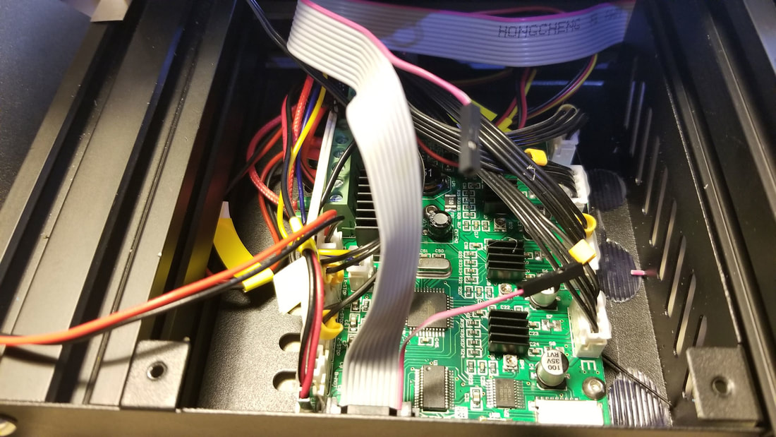
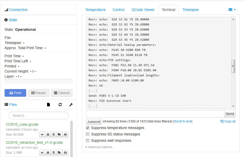
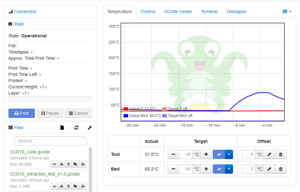
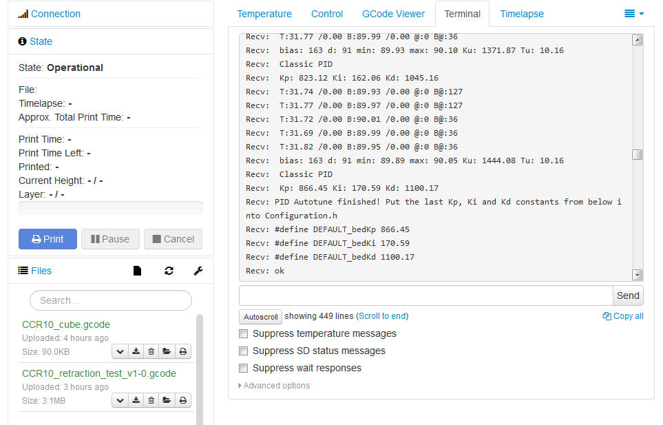
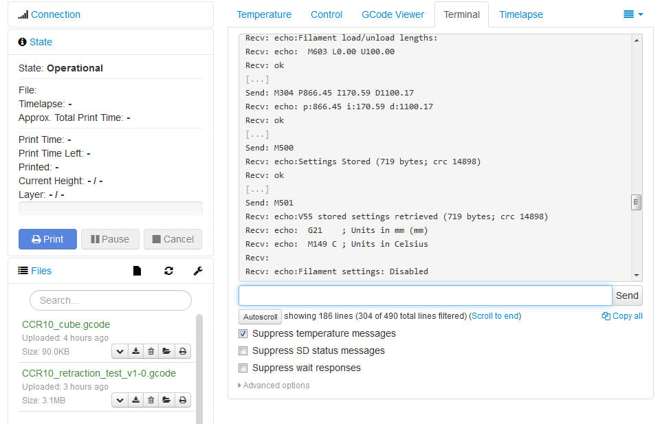
The firmware upgrades are a mixed bag, I am not sure if there will be a big difference in print quality to the stock firmware but they do make things simpler. However the Ender 3, like the original CR10 has a pretty minimalist mainboard with only 128KB of space for Marlin, which requires some compromises. I found that I could not compile Marlin 2.0 with all the bells and whistles, the most memory intensive optional features were the LCD, SDSUPPORT and UBL (or Universal Bed Leveling). It's one of those puzzles where you can pick 2 but can't have it all, so I lost SD Support in favor of some basic onboard leveling and the LCD (I was able to get all 3 at one point but it used almost all the space and warned of likely stability problems so I ditched it). So without SD Support I just need to print from OctoPrint which normally works fine. If I can get this working with a degree of reliability and am happy with the print quality then I will consider upgrading it to something with more memory or possibly a 32 bit controller.
Still yet to be added are:
All in all, I think I can finally see the light at the end of the tunnel.
I also added a 3D Touch probe, because when I am just trying to get the damn thing working, why not double down on the possible points of failure (but I had the printer and wiring loom already in a minor state of disassembly). So whats the problem now? I lost the damn nozzle (doh). So now I'm waiting for a pack of those, but otherwise the printer is back together and ready to hopefully rock and roll.
To date this is where it stands currently. Aside from upgrades, some items were replaced on suspicion and others to test, and others because they were faulty).
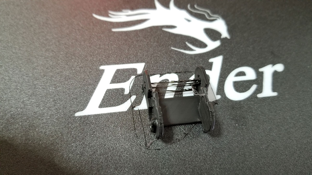
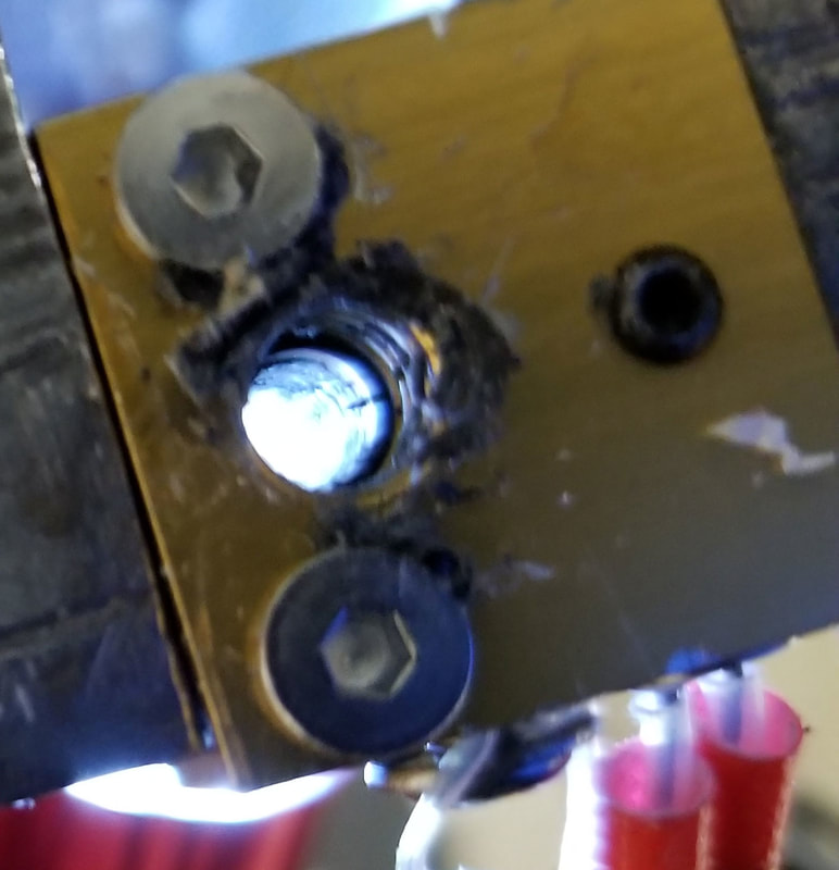
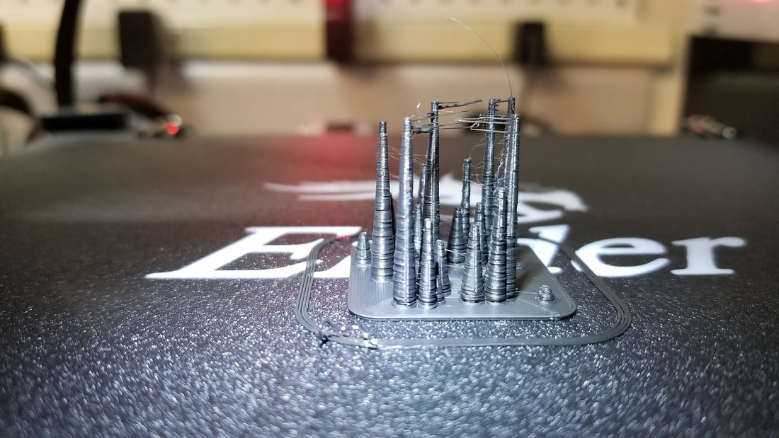
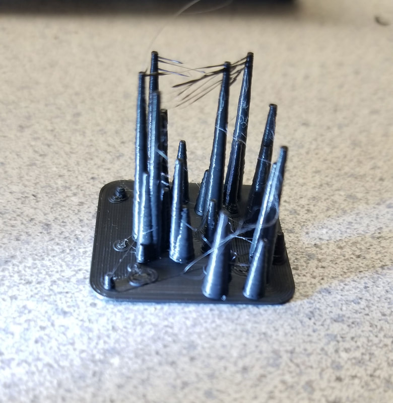
- New hot end using a mix of E3D V6 and clone parts (due to issues with the original hot end clogging due to the Bowden setup).
- New Bowden tube and fittings (did not help the original hot end problems but I kept them on there)
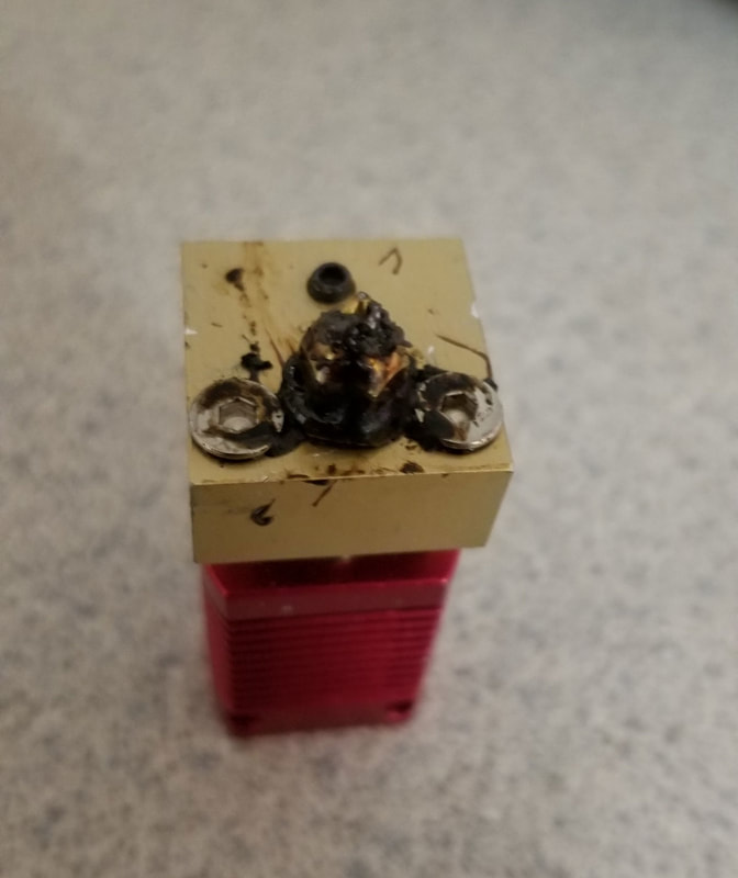
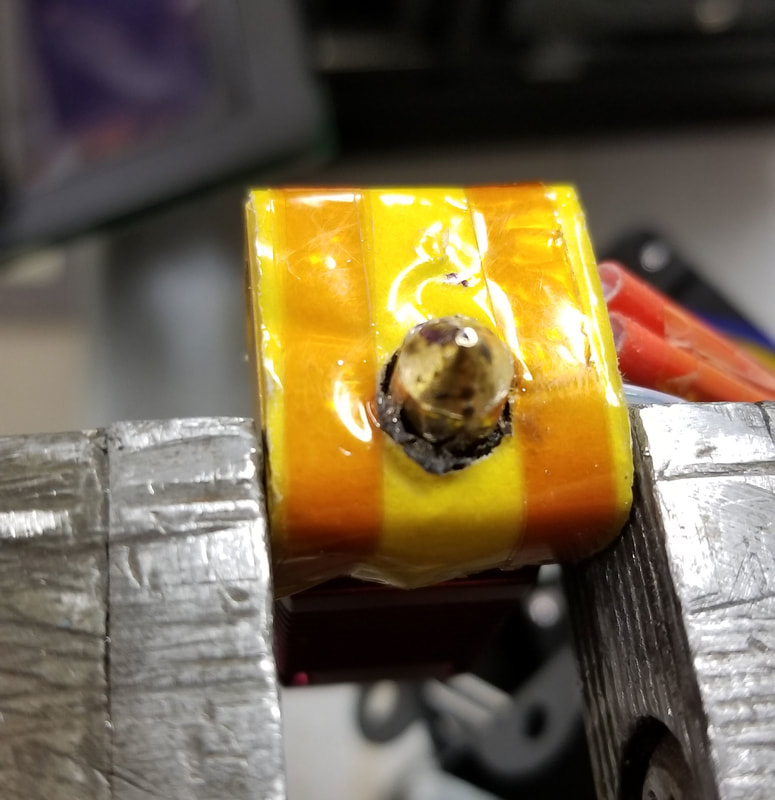
- New Themistor (original did not seem to be accurate). The first replacement was accurate but the new one is a cartridge which I prefer.
- New heater cartridge (I bought a few previously and picked the one closest to 14.4 ohms).
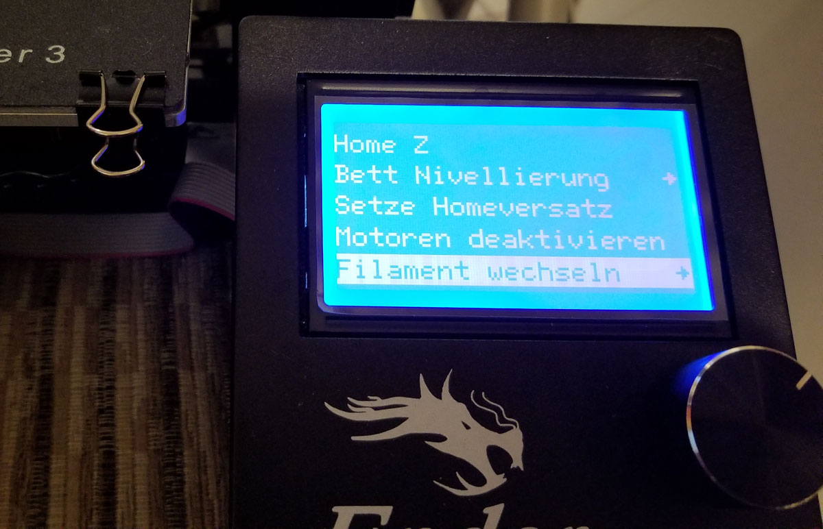
- New firmware (tried both Marlin and TH3D), currently running TH3D v1.8J (running that v1.8 since I could find instructions to get the touch probe up and running quick, but may try v1.9 or Marlin again)
- New build tac - using PEI now, though nothing wrong with the original build tac except for the texture.
- 3D Touch Probe, which seems like it will be a time saver.
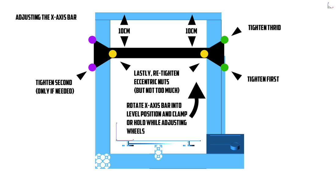
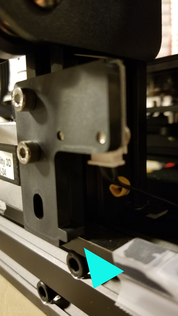
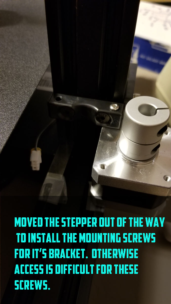
- Added a shim to the Z-motor mount which seems to have reduced binding on the Z-Axis leadscrew.
- Moved the Y-Axis limit forward, which seems like a common problem as it has tons of room in the back but goes right to the edge when moving the plate all the way back.
- Moved the Z-Axis limit up, and then removed it completely when I added the 3D Touch.
- Swapped the extruder gear, this was cheap and probably a worthwhile upgrade.
- Swapped the extruder with modified parts allowing spring adjustment (then swapped back to stock when I found it was too tight with the modified extruder).
- Adjusted Vref of the Extruder and verified the rest (values are in a prior post somewhere down there).
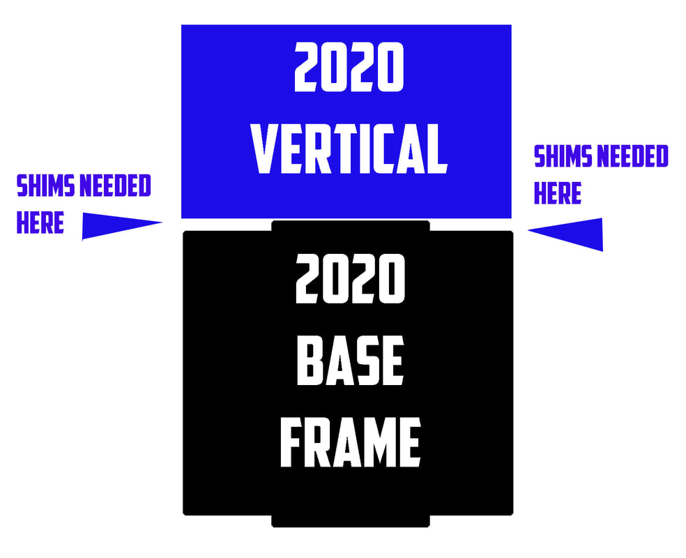
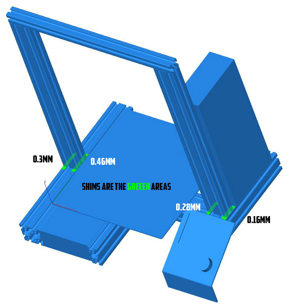
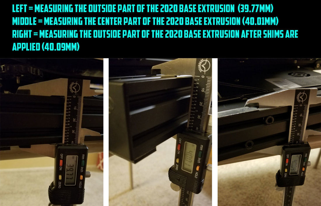
- Shimmed the vertical frames where they meet the baseframe and straightened the pre-assembled base frame since it would not sit flat when I got it.
The firmware upgrades are a mixed bag, I am not sure if there will be a big difference in print quality to the stock firmware but they do make things simpler. However the Ender 3, like the original CR10 has a pretty minimalist mainboard with only 128KB of space for Marlin, which requires some compromises. I found that I could not compile Marlin 2.0 with all the bells and whistles, the most memory intensive optional features were the LCD, SDSUPPORT and UBL (or Universal Bed Leveling). It's one of those puzzles where you can pick 2 but can't have it all, so I lost SD Support in favor of some basic onboard leveling and the LCD (I was able to get all 3 at one point but it used almost all the space and warned of likely stability problems so I ditched it). So without SD Support I just need to print from OctoPrint which normally works fine. If I can get this working with a degree of reliability and am happy with the print quality then I will consider upgrading it to something with more memory or possibly a 32 bit controller.
Still yet to be added are:
- TL-Smoothers (reviews look promising and they are cheap)
- Titan extruder (may even try the Aero, though it will be all clone parts due to the expense).
- Upgraded blower fan (on the slow boat from China right now)
All in all, I think I can finally see the light at the end of the tunnel.
 |  |


 RSS Feed
