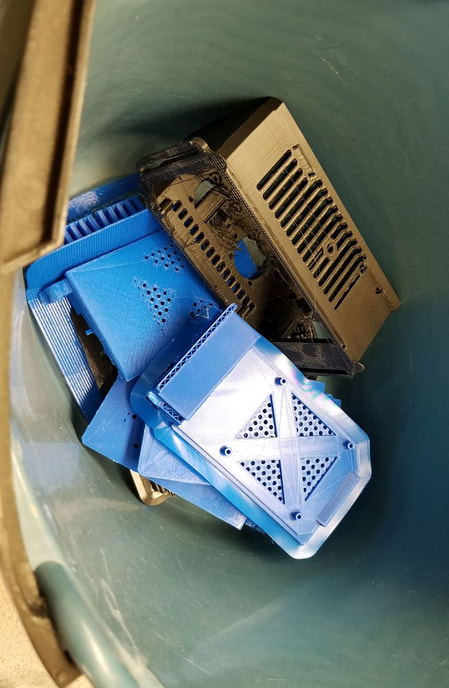
My Stoopid Stuff
  • Home
  • Projects
  • Blog
  • Lec'tronics
  • Links
  • CNC
  • Quick Recipes
  • 3D Printer Tips

Nothing but problems with the Anycubic Kossel Plus

6/30/2018

0 Comments

 
Picture
bucket of fail
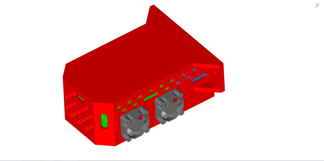
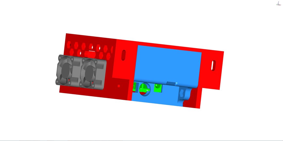
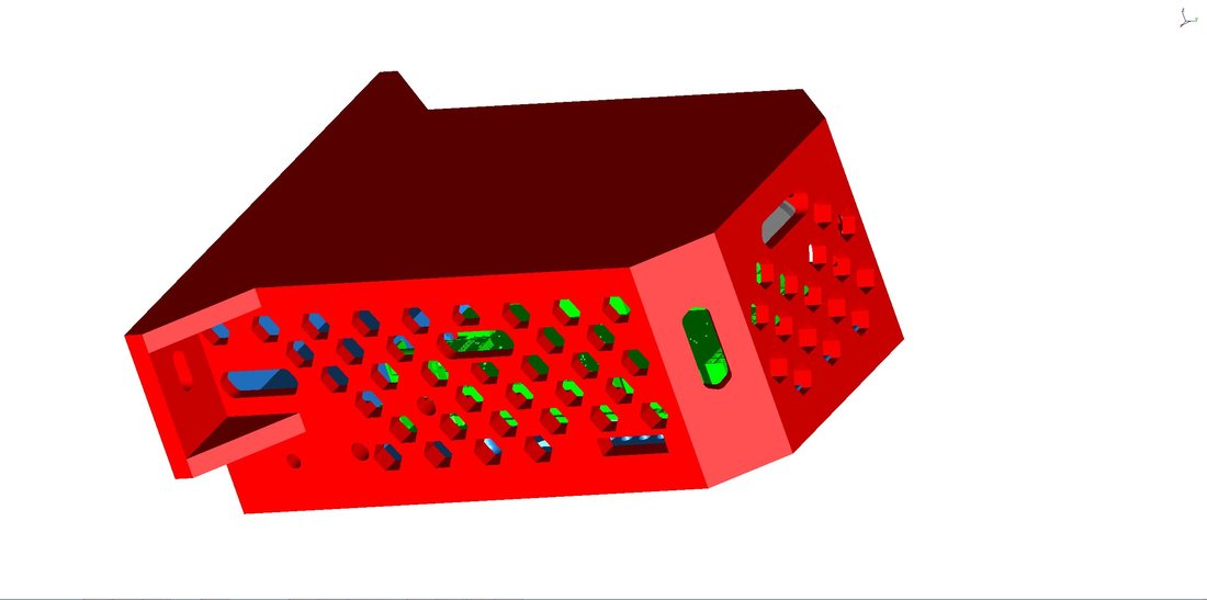
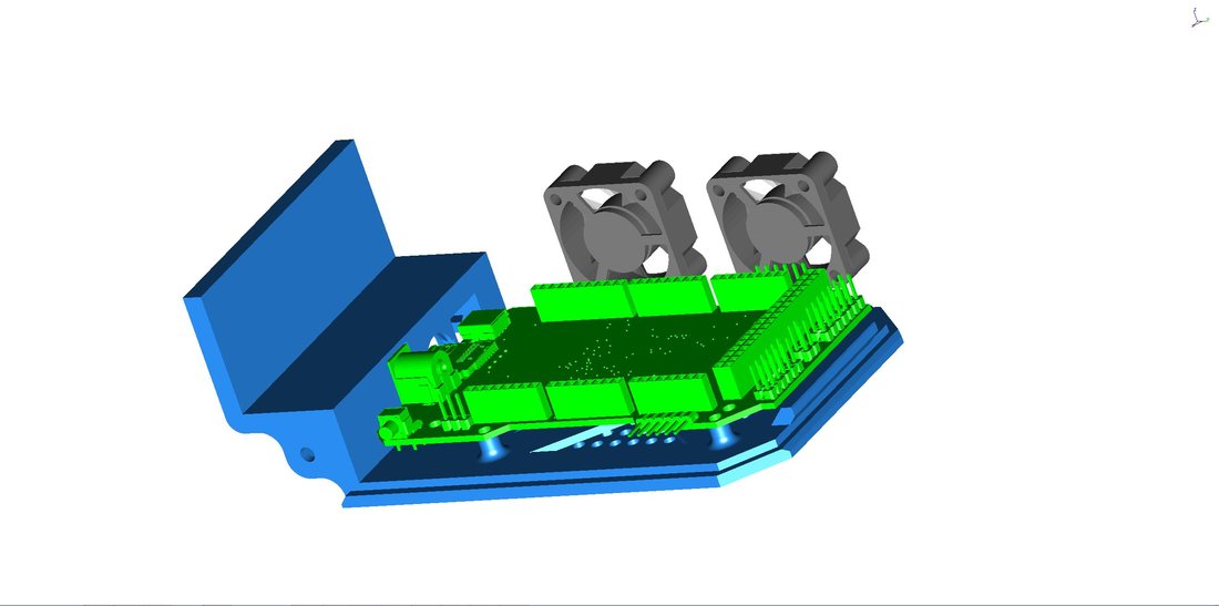
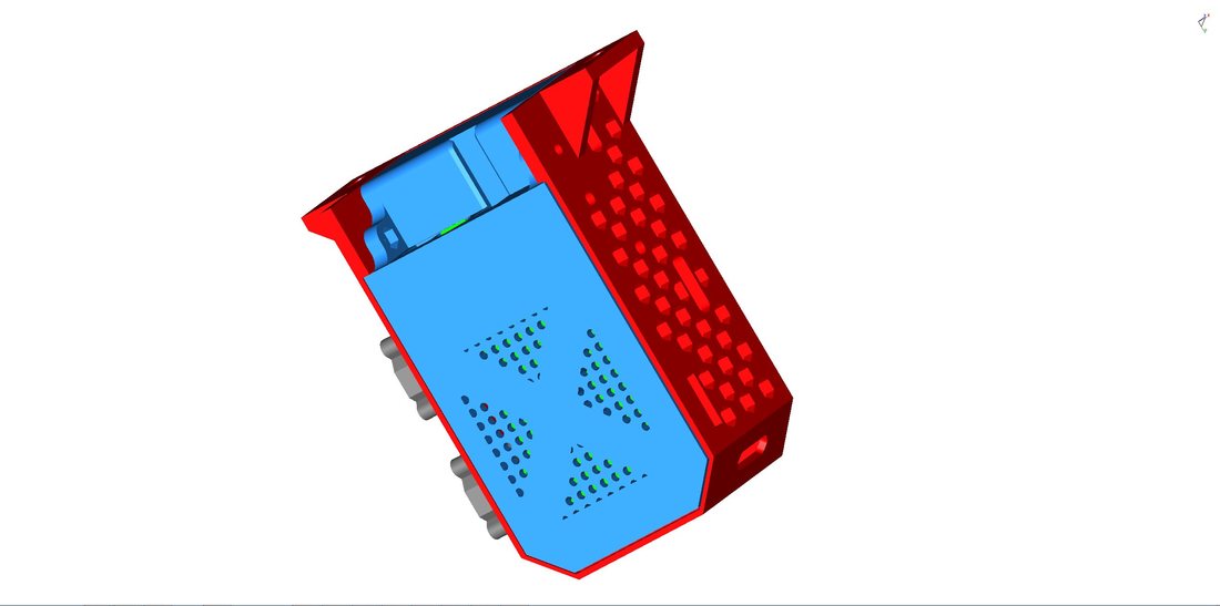
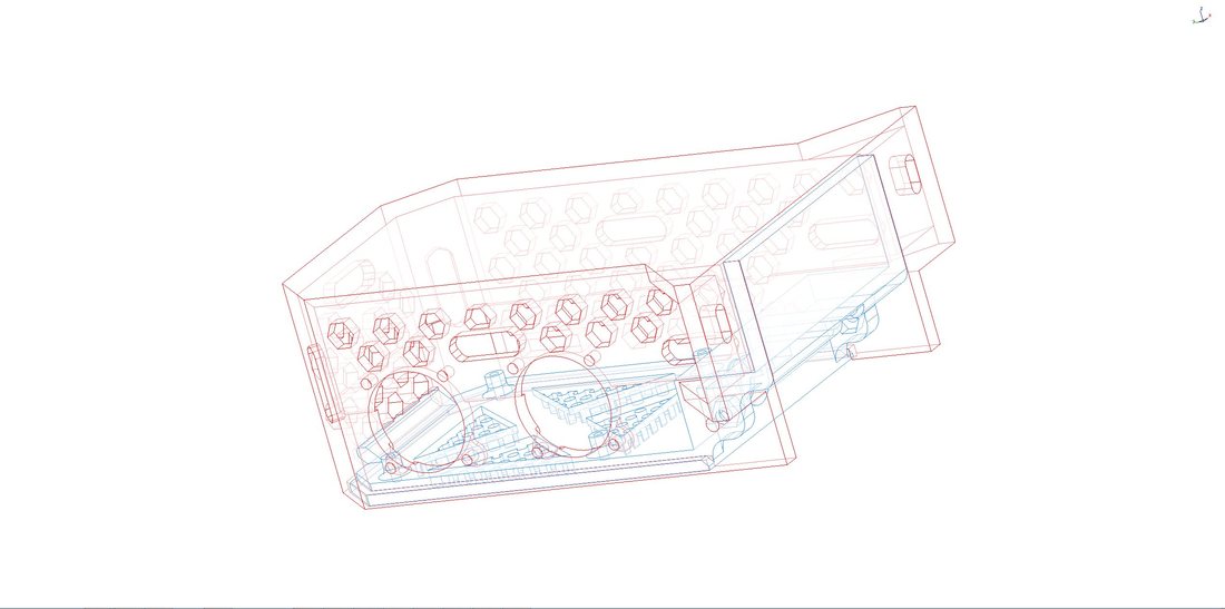
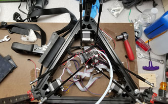
After swapping the plastic corners with aluminum, waiting on replacement linear rails from China, adding fans, replacing stepper drivers, a broken limit switch (my fault), and the build tac surface with PEI (today), I am still throwing out part after failed part due to level shifts.  I still have hope though, and plan to replace the Tri-Gorilla board with the RE-ARM + RAMPS.  All I am waiting for is to print 3 damn parts so I can put the new electronics in a box and mount them externally.  Seems like a big ask from this printer, but I still have hope I can fix it.  By the time I get done it though, I will be using the steppers, rails, arms, extruder, heated bed, PSU and the 2020 extrusions along with some other bits from the original kit.  In fairness it did work out of the box for several prints before developing issues, and I have not contacted the manufacturer about any of these problems since the linear rails were swapped.  Still though, as a first printer I would not recommend the Anycubic Kossel, it is just too much work even for somebody who has some prior experience with CNC.  Deltas also seem to be more difficult to troubleshoot than a Cartesian style printer.  On that note I bought an Ender 3 last night, which has a similar build volume and a host of it's own problems, however I have the upgrades planned for that and am gonna try and get the Kossel up to speed beforehand, maybe between them I can get some good parts.

I did not even mention the latest problem today, which burned up an hour and got me thinking about all of the above prior issues - and the possibility that the machine may be either self aware or possessed.  I did not have a vat of molten metal, and could not find an old priest and a young priest on short notice, so I had to start taking things apart to investigate myself.  Let me back up, I just installed some PEI build surface today due to many issues with PLA curling on the glass (tried hairspray, purple glue stick and cursing, nothing worked).  Since the build surface was a it wee bit thicker I had to re-level it.  Here is where it started acting very odd.  After installing the level sensor, the first part of the process is to home, but it went to the home position and just grinded away up there as though it was trying to sense the bed.  Multiple re-sets later and no improvements, but other weirdness led me to think either one of my limit switches or the z-probe was faulty of not connected.

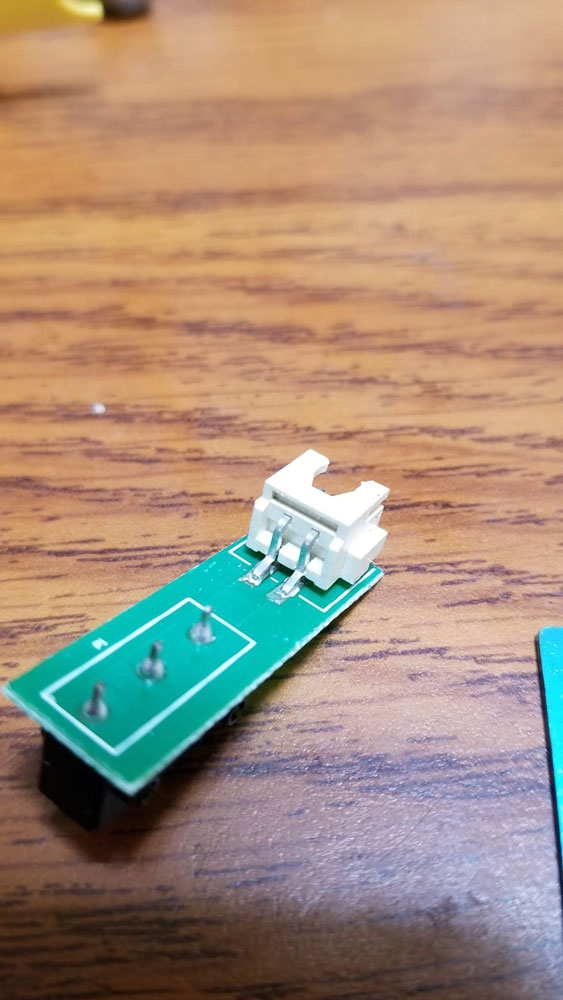
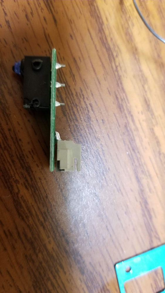
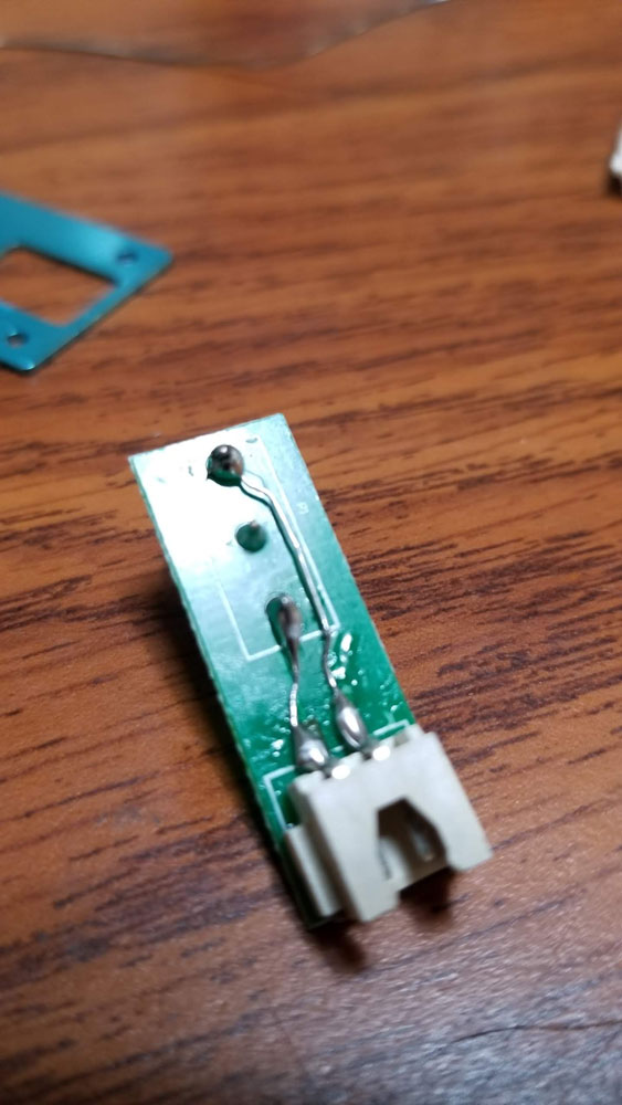
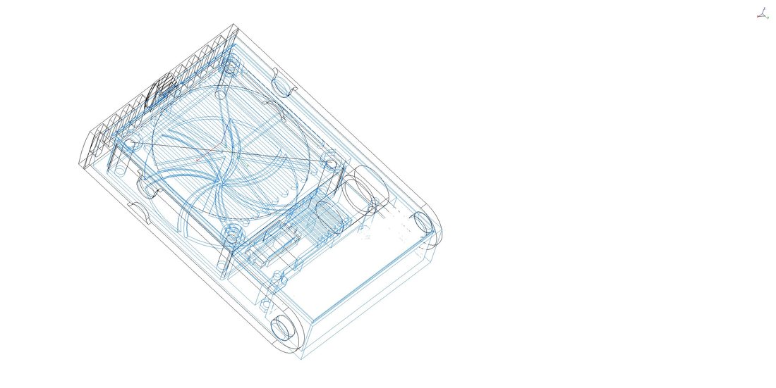
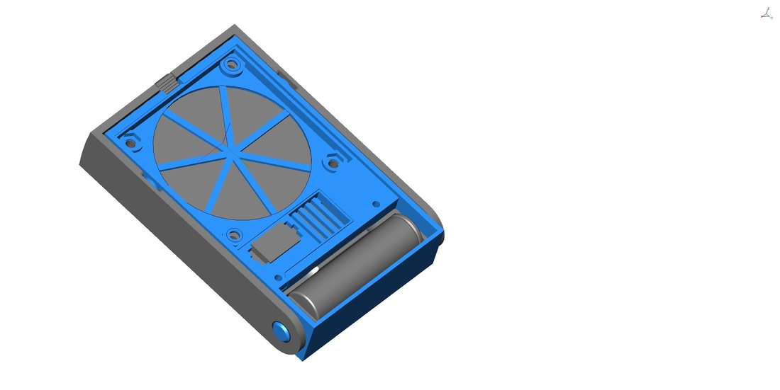
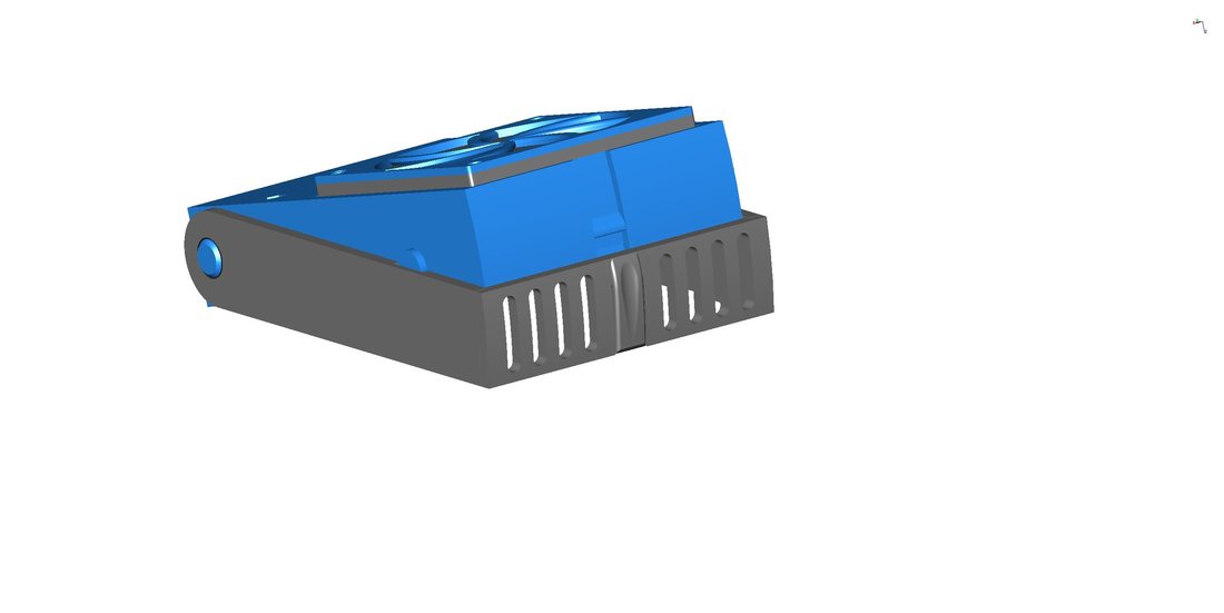
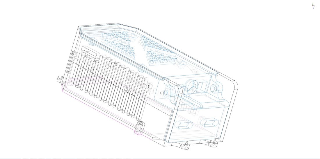
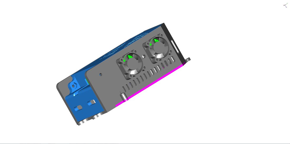
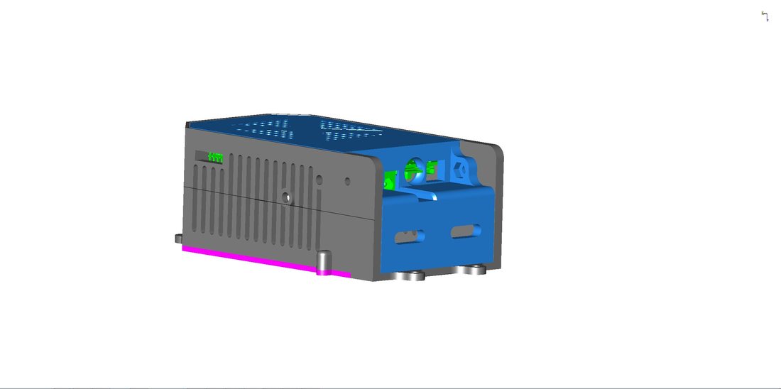
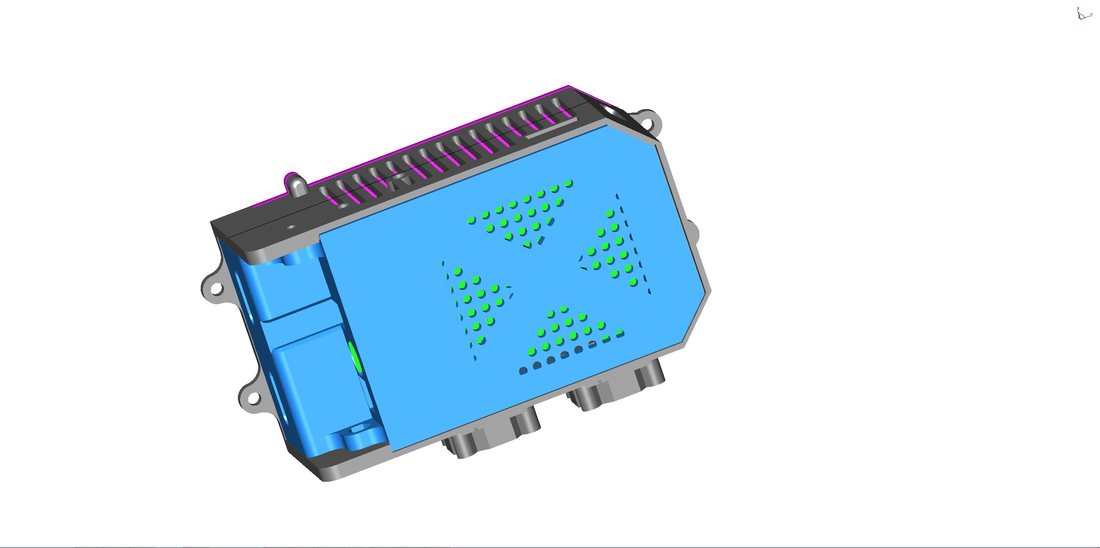
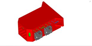
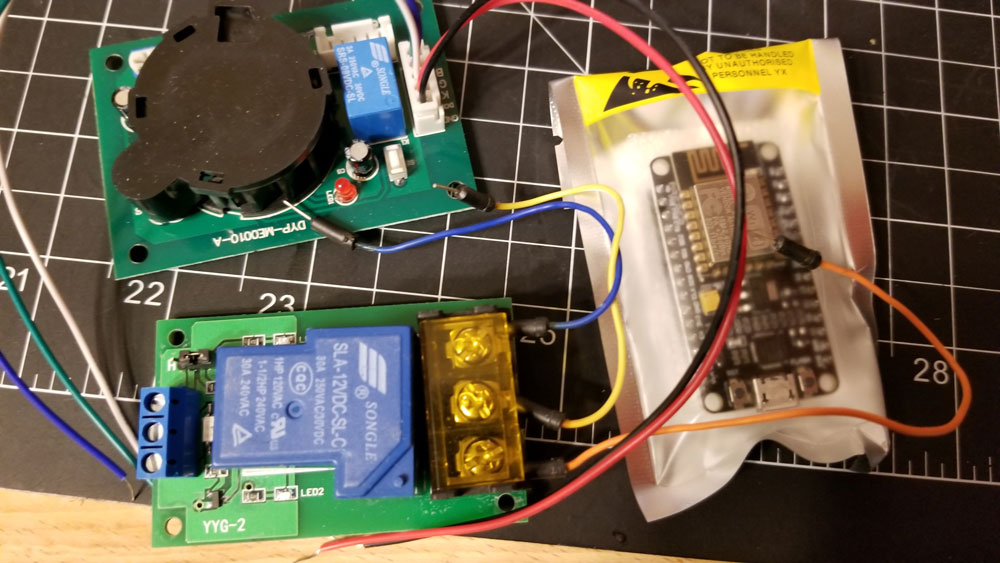
I broke out the meter and tested each switch, X, Y and Z limits are good, but the Z-probe was not.  For the record the limits are all NO (normally open) which is good since if they fail the board will lose the signal on them and hopefully keep the head from doing damage.  I took the z-probe apart and found that the connector had cracked at solder joint that holds it to the board.  The connector is surface mounted (not though hole) and there is a small gap as well below the connector - so all the torque on the connector is relayed to the surface mount pads on the board - which is poor design IMHO.  I added some gorilla glue below the connector to fill the small gap and provide some mechanical bond between the connector and board, then (since the there was no longer continuity between the connectors' pads and the switch terminals I had to solder some wires (actually used some wires cut off resistors), and then covered the exposed wires with some more glue to insulate them.  After that I re-tested the switch and it worked, however I forgot to plug it back in which led to a minute of head scratching before the light bulb went off (dimly) and I was able to get the auto-leveling working again.  For reference here are some pics of the inside of the z-probe.


Update 10/19/2018 - The Anycubic Kossel is now printing like a champ.  A couple things that may have attributed to the layer shifts were the board (which is now swapped with a Re-ARM + RAMPS 1.6 running Marlin 2.0), and some new clamps I installed on the heated bed.  The new clamps are an improvement on the prior design, and tightly hold the bed from the sides and the top which should remove any possible shifting due to the bed clamps.
0 Comments

Design for a Soldering Fume Extractor from an Old CPU Cooler (and other parts)

6/28/2018

0 Comments

 
I found a 70mm CPU cooler for a long ago defunct socket type, and hated to see it go to waste, so what better way to save some money than to spend some money on Ebay for a new project... Yeah.  Well got to tinkering with what I thought would be something simple to use the fan as a solder fume extractor and it this is what happened:
Picture
Yep, not your Dad's solder fume extractor that is.  It's got:
  • TP4056 based Lithium Ion Battery management with USB charging.
  • 3V to 12V boost regulator
  • 3.7V-16.8V LED Lithium Battery Capacity Tester Indicator
  • Illuminated latching power button
  • And my old 70mm case fan
  • Rear defogger
  • and Power seats!
It is designed so it can either stand or sit in a more horizontal orientation (also my favored orientation lately).  Not sure how well this will work, but will bench test it first to see if it will be worth while once the parts get in from China.  I'm planning to use an off the shelf single 18650 battery holder for this since the contacts to DIY a holder are either too kludgey or too damn expensive.  The battery and holder in the pics are just standing in for now - they are models that I got off Thingiverse - here and here. (If I ever get my printer to spit out a decent print then this will be next up after the RE-ARM case which is on my 4th attempt at printing currently.
0 Comments

Enclosure for a Re-ARM + RAMPS 1.5 (third version)

6/24/2018

0 Comments

 
I made a few different versions of the Re-ARM + RAMPS enclosure.  This one is designed to mount outside the printer on the 2020 rails, which should make keeping it cool a bit easier.

Models used from Thingiverse are:
30mm Fan
RAMPS 1.4
RE-ARM
Picture
0 Comments

RE-ARM and RAMPS 1.5

6/23/2018

0 Comments

 
Picture
The Anycubic Kossel comes with what is called a Tri-Gorilla board which I believe is a RAMPS board and a (16 bit) Arduino Mega integrated on one board.  It works and is cheap, but for a number of reasons it is just capable of running a delta style printer like the Kossel Plus.  The upgrade path is usually a 32 bit board such as a duet, smoothie board, MKS Base or the Re-ARM + RAMPS combo (from most expensive to cheapest).

So after checking the options, a while back I picked up a RE-ARM and a RAMPS 1.5 board which is on the lower end of the cost for 32 bit goodness.  These two boards act like the brains and nervous system of a 3D printer.  Along with running the software (either Smoothieware or Marlin 2.0), they also manage the power necessary for the stepper drivers, the heater bed and the extruder/s.  The RAMPS is a draughtboard designed to manage stepper drivers and heater MOSFETS for an Arduino Mega originally, and it has unofficially evolved through several iterations to improve some things while completely ignoring others.  I decided to pick up the latest iteration which is the 1.5 which I don't see too many people using, but appears to have better management of the MOSFET's cooling.  One of the big considerations with any RAMPS board seems to be the connectors which are generally regarding with suspicion as being just barely spec'ed out for the currents needed on some printers.  Mine should be OK however and I don't expect any issues.  The other thing to look out for with RAMPS board (actually one of the other things, is poorly spec'ed components) like MOSFETs and capacitors.  It is tough to check these since many Chinese boards may use questionable MOSFET's in the first place, and the caps may be hard or impossible to read, so it is just one of those things to be aware of.  A nice alternative to RAMPS is the PICA which addresses the questionable build quality, suspect connectors and appears to me to be a well designed board.  It is also 4x the price of a typical $10 RAMPS board.  The PICA is also not out of the box compatible with the RE-ARM, but it is on my list once I get things running well enough.  For now though I just want to get going with a 32 bit board since I am having all sorts of failed prints (and I want to do it anyway). 

As for the Re-ARM itself, the major consideration is that it runs on 3.3V and is replacing an Arudino Mega which runs on 5V.  This means that care needs to be taken with anything plugged into the Re-ARM or RAMPS board that may send a 5V signal though to the Re-ARM - which could blow out one of the Re-ARM's IO pins since they are not protected.  Most things should be OK in my build since I use mechanical limit switches.  The other concern I had with the Re-ARM which turned out to be unfounded, was that it would not be able to provide 5V to the MOSFET's on the RAMPS board - turns out they designed the Re-ARM with 3.3v to 5v level shifters for the outputs used for the MOSFETs so that is all good - these are only for the outputs however so the inputs still need to be connected with care so as not to give them more than 3.3V.

Last night I was able to first upgrade the stock Smoothieware on the Re-ARM board, but then decided to try installing Marlin 2.0 again.  I'm not sure why I want to use Marlin, but it's what the cool kids are doing so I was happy to finally get that working.  Unlike Smoothieware though, Marlin is not easy to get started with.  Smoothieware just requires downloading a firmware.bin then you load that on a 32GB SD along with a config file and restart the Re-ARM, then you are in business.  Now the config file is nothing to sneeze at though, it included all the pin definitions and settings that will be used (and is actually more complicated than Marlin's configuration for that reason).

Marlin on the other hand requires downloading Atom.io, then installing PlatformIO - from within Atom.io (which was nothing but problems - make sure to run it as administrator to solve a few of them).  Once that is running I had to open up the unzipped Marlin 2.0 directory in Atom, finding the configuration.h, editing that for the type of board and other parameters being used for the printer - I used a sample config for a kossel and added my settings.  Then compiling the whole mess into a firmware.bin which inconveniently is just saved in a subdirectory buried deep with the one being worked on (mine was inside "\Marlin2.0\Marlin-bugfix-2.0.x-6-22-2018\Marlin-bugfix-2.0.x\.pioenvs\LPC1768\firmware.bin" (so no option I found to save it anywhere else).  Compiling also hit a few snags since I accidentally commented out a if statement and had to find it to fix one error.  Another error ("Marlin\src\libs\buzzer.cpp:63:11: error: '::tone' has not been declared") was due to having set up the speaker up for my display board.  Fixing that required disabling the speaker - on line 1629 in configuration.h - since it is not implemented yet for LPC1768 (Marlin 2.0 is still in development so this is something that will get fixed in time):

https://github.com/MarlinFirmware/Marlin/issues/8211

After a few hours, I was able to get a good Marlin2.0 firmware.h, and loaded it up on the Re-ARM without a problem.  So next up is getting it all put together which should be easy but really it is not since there are some quirks of the Re-ARM such as requiring a special cable for the display (due to the Re-ARM running at 3.3v versus the 5V typical of the Arduino Mega it replaces).  There are other considerations as well, but lets just say I am taking it slow, so I don't fry something. 

In the mean time I am also working on a means to hold the Re-ARM + RAMPS 1.5 boards and have come up with a two part enclosure that will mount in the same location as the current board in the Anycubic Kossel Plus.  It is not a perfect design, I may re-design the way the lid attaches with screws, sometime down the road, but for now this should get me started. 

Models used from Thingiverse are:
30mm Fan
RAMPS 1.4
RE-ARM

0 Comments

Upgrading the Kossel - Delta Aluminum Corners

6/18/2018

0 Comments

 
Picture
One of the corners on my delta had a small crack which was probably nothing to worry about, however I had noticed that the bed was difficult to get square to the side posts (actually it was not possible to get square since the side posts had a slight tilt to the inside.  Since I would need to disassemble most of it to correct that fault I decided to upgrade the corners with aluminum extrusions.  There are 2 types of aluminum corners  which I had found online.  I bough the cheaper ones from Ebay which seem to work fine.  The corners I would have bought if they did not cost as much for shipping as the parts themselves, were the corners from RobotDigg, since they appear to be milled on several surfaces and overall better designed (they utilize flange bearings for the rollers also which is some added cost).  The cheap-o aluminum corners on Ebay however seem to be just fine, though they are a pain in the ass to assemble due to the poor design for tool clearance (this was a problem with installing the motors).  Funny thing is that the pics on some of the Ebay auctions for the corners show them missing holes and with wavy extrusions, though mine were fine in the regard (they probably took the pics of some pre-production models). 

To avoid the screw ups of my initial assembly I put some thought into how I was gonna put this together the 2nd time around.  I decided that I needed to first get a flat surface to hold the corners against, for this I used some old MDF with a piece of that brown pegboard material without the holes (sorry can't recall the proper name).  Really I just needed something flat and strong enough to pass bolts through.  After that I loosely assembled the new corners to the 2020 extrusions making sure not to tighten anything down.  I used the loosely assembled base as a template, and marked 3 holes, nothing had to be perfectly accurate at this point, just 3 holes per corner, with one each using the two holes in the corner parts, and another in the square hole so I could pass the limit switch wires though the board (otherwise they would get squished - or I would need to remove the wires from the vertical posts).  Next I stacked the bottom frame, then the top frame, and installed the corner posts though both without tightening anything (here is where I had to pass the limit switch wire through the hole in the board).  Then I installed bolts through one of the two holes in each of the corner pieces (I did not have enough so only used 1 through bolt per corner) - these bolts were only loosely tightened also.  Next I used a ratcheting tie down strap to cinch up the slack in the frames, and had to use some plastic plates I had around to keep from marring the frames and take up some of the slack since the ratcheting strap does not have a fine enough adjustment.  Once the frames were cinched up, I then tightened the bolts that held the corners to the board, which should bring the frames as close to perfectly parallel to each other as needed here.  After the bolts were tightened, I checked the 2020 rails to make sure they were positioned similarly in relation to the corners and adjusted as needed (this is more cosmetic, though the top rails for the base should be as close to identically spaced with respect to the corners as possible since they will mount the bed leveling clamps).  After the rails were positioned and it looked good, I finally began to tighten the screws that hold the 2020 rails to the corners, doing the vertical posts first.  Some of the screws were not possible to tighten so I just got all the ones I could reach and made sure they were as tight as reasonably possible before removing the frames from the board.  One other thing that would have helped me here would be using better M4 T-nuts.  The nuts they used to assemble the frame at the factory are just square nuts, which have a nasty tendency to wedge into the slots rather than spin into position and hold like a clamp.  It is hard to tell if this happens unless the screw is backed out and does not wobble around (meaning the square nut got wedged).  If I had them, I would have replaced all the square nuts with t-nuts beforehand.

The final step was removing the frames from the board, and the rails, and then tightening the remaining screws that I could not reach before and then re-assembling the frame.  The result was that the top and bottom frames are now parallel to each other and since I set the vertical rails each at 60mm between base and top, each side post should have set the top and bottom frames the same distance from each other in each corner.  Now when I square the build plate to the side posts I no longer see what appears to be a tilt to the inside on each post, they are nearly square as I can see (using a machinist square).  I pretty sure the aluminum corners will also help with the rigidity of the printer as well. 

I also ended up breaking a limit switch sometime during this process, so was fortunate that I was watching it closely when I re-leveled it the first time.

The one major problem with the cheap aluminum corners is the lack of space for tools, which makes installing the steppers a real pain.  I had to cut down an Allen key to get the necessary clearance and start the screws using my pinky fingers which was not fun.  If they had drilled some access holes it may have been at least possible to start them with an Allen key but I suspect that whoever designed these did not actually test them in use.  That said, they do work and all the holes are where they need to be, including the holes for the pulleys and the hole for the nut used for the top stop. 

One final note - the stock m3 screws used for the pulleys with the original Anycubic frame were not not long enough for the new aluminum corners, so I had to get some longer bolts.  I think they were M3x25mm bolts that I needed to use (the originals were M3x20mm). 


0 Comments

Initial Design for a Smoke Detector Relay with NodeMCU

6/8/2018

0 Comments

 
Picture
Working on a smoke detector design that will monitor for smoke, and temperature, send me a text if there is a problem and also allow my to remotely reset a device.  It will use a NodeMCU and some parts from Ebay.  I posted more under the Lec'Tronics section.

0 Comments
    Picture

    Stoopid Me

    Welcome to my Stoopid corner of teh Internet.  It's mostly gonna be 3D printing stuff, but I also post some recipes, projects, and the occasional rant here as well.  More Stoopid stuff is updated regularly.

    I recently joined the Amazon Associate program, so some of the links on this site are Amazon affiliate links. This means that, at zero cost to you, I will earn an affiliate commission if you click through the link and finalize a purchase.  This will help to support this site, and pay for more Stoopid Stuff.

    Archives

    March 2023
    February 2023
    January 2023
    November 2022
    October 2022
    September 2022
    August 2022
    July 2022
    April 2022
    February 2022
    January 2022
    December 2021
    November 2021
    October 2021
    September 2021
    August 2021
    July 2021
    June 2021
    May 2021
    April 2021
    March 2021
    February 2021
    January 2021
    December 2020
    November 2020
    October 2020
    September 2020
    August 2020
    July 2020
    June 2020
    May 2020
    April 2020
    March 2020
    February 2020
    January 2020
    December 2019
    November 2019
    October 2019
    September 2019
    August 2019
    July 2019
    June 2019
    May 2019
    April 2019
    March 2019
    February 2019
    January 2019
    December 2018
    November 2018
    October 2018
    September 2018
    August 2018
    July 2018
    June 2018
    May 2018
    April 2018
    March 2018
    February 2018
    November 2017
    September 2017
    August 2017
    June 2017
    December 2016
    October 2016
    September 2016
    July 2016
    March 2016
    February 2016
    September 2015
    August 2015
    June 2015
    May 2015
    April 2015
    March 2015
    February 2015
    January 2015
    December 2014
    November 2014
    October 2014
    September 2014
    July 2014
    June 2014
    May 2014
    April 2014
    March 2014
    February 2014
    November 2013
    August 2013
    July 2013
    June 2013
    May 2013
    April 2013
    March 2013
    January 2013
    December 2012
    November 2012
    October 2012
    September 2012
    August 2012

    Categories

    All

    RSS Feed

      Contact Form (Name is optional)

    Submit
Powered by Create your own unique website with customizable templates.