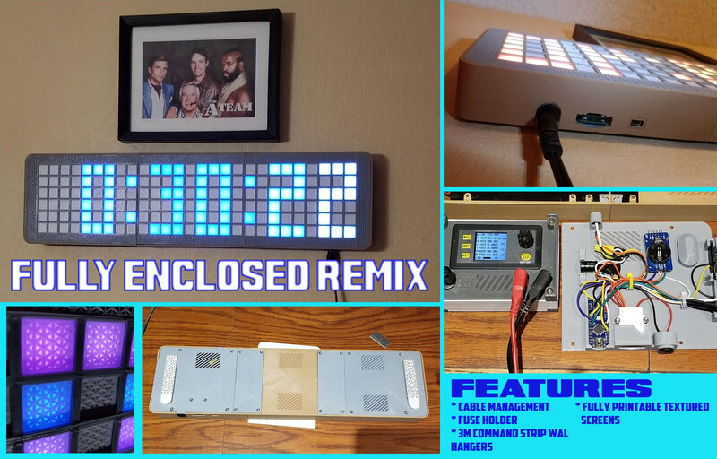
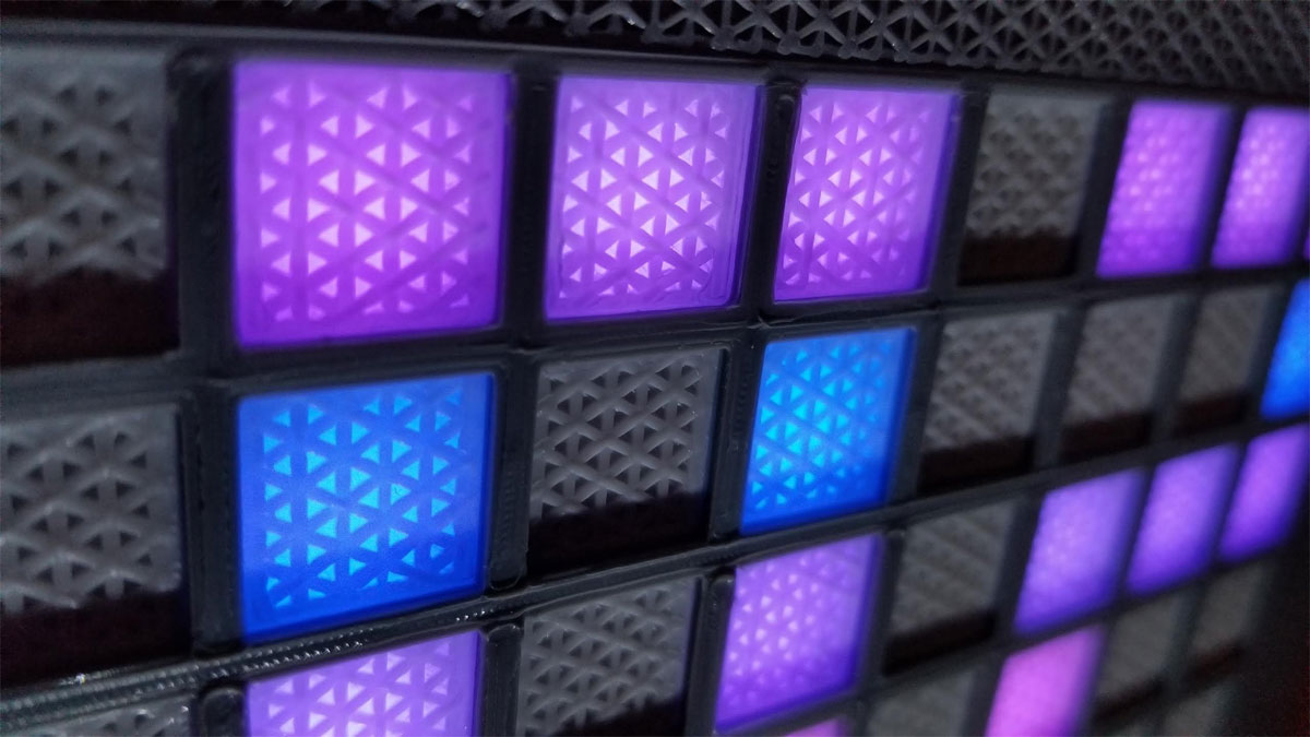
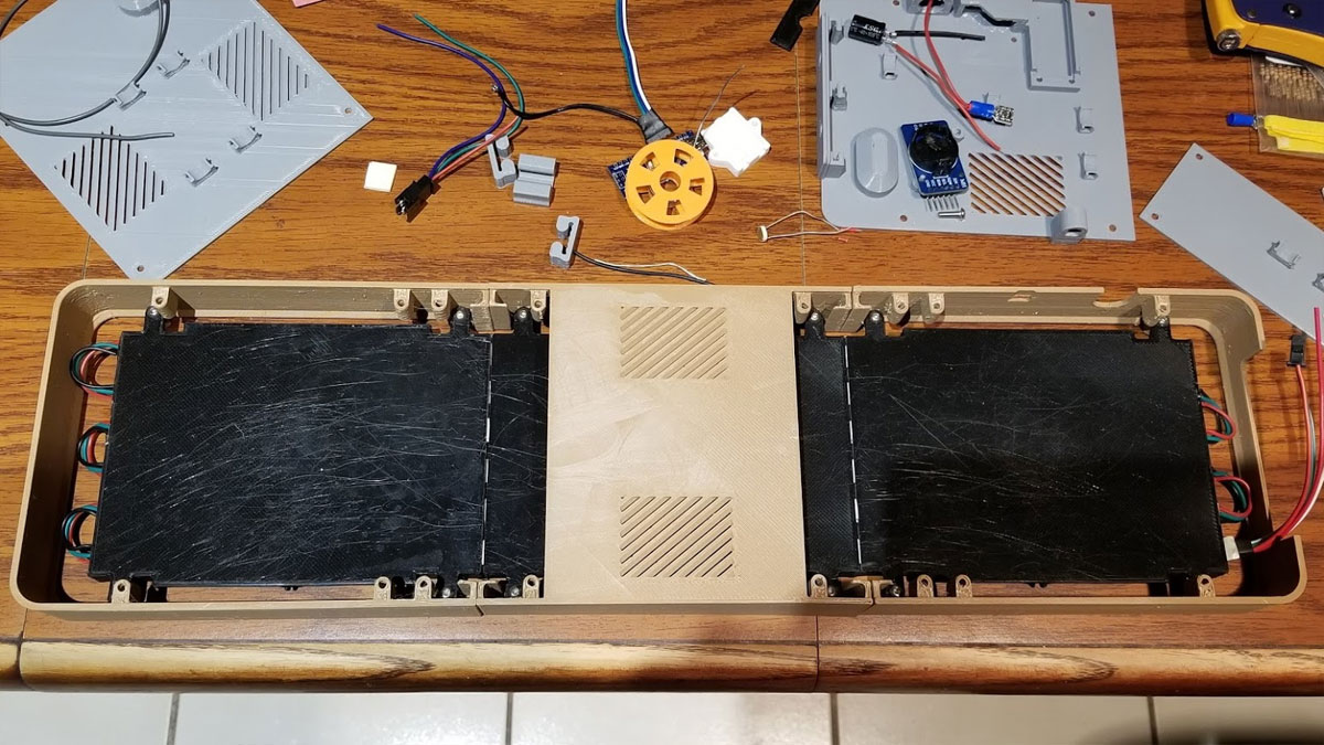
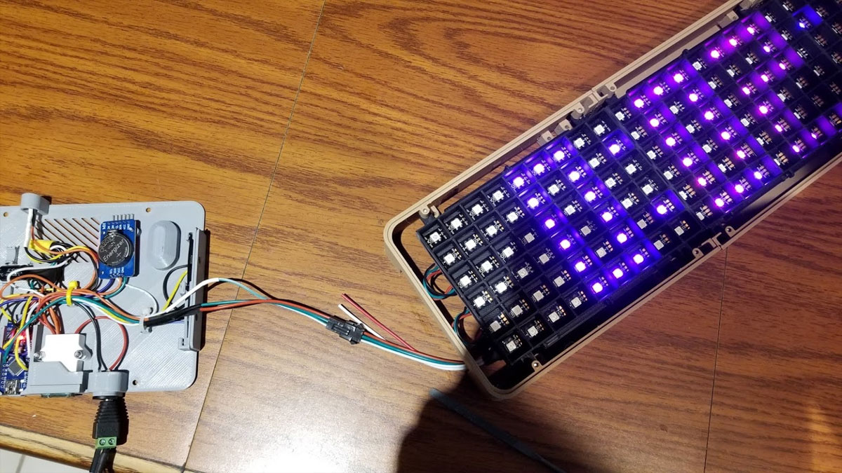
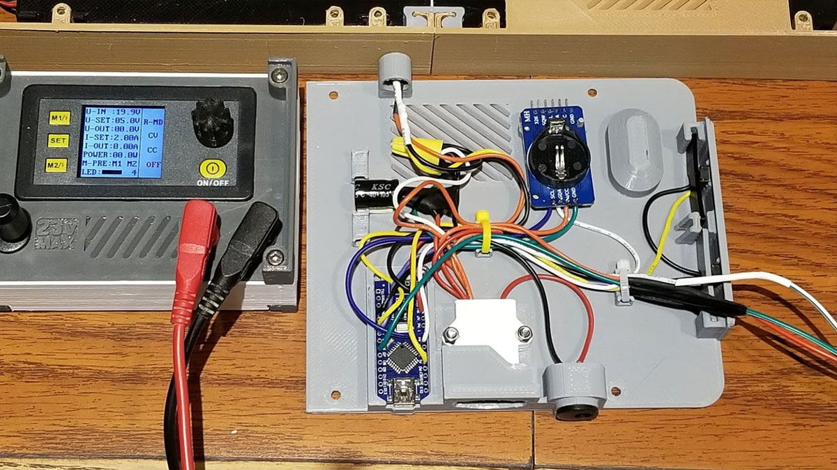
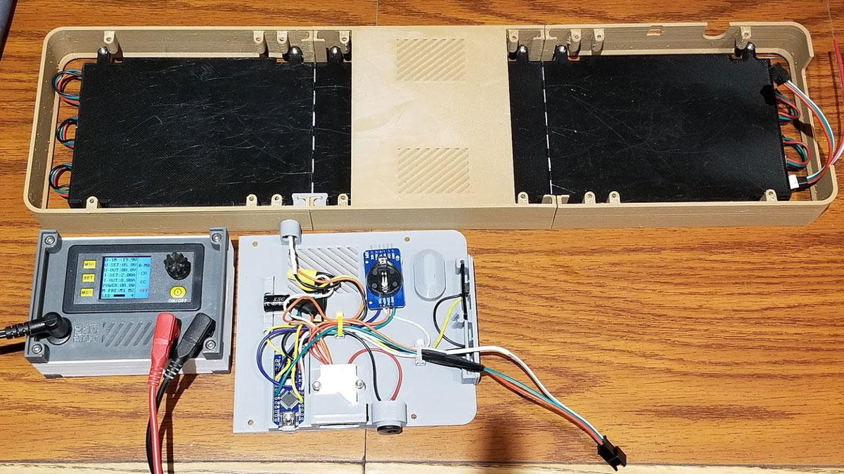
The electronics are hooked up just like the original model, but I added a 1000µF, 25V electrolytic capacitor between the positive and negative power connections, and a 2A automotive fuse and printed fuse holder. I also added a LDR which faces upwards and automatically dims the clock when the lights are out (this was an option with the code which was included with the original model). I also increased the max current in the code to 1250mA, which helped with the brightness since the filters are two 0.2mm layers of white PLA. However even with the increased current (since only a few pixels are ever lit), it only pulls around 300-400mA total from the 5V supply for a whopping 1.5W or so draw. Once it was mounted I realized that I did not actually need it as bright though, so the 2nd or 3rd brightness setting is about perfect, or I can just let the LDR set it automatically and that's pretty good too.
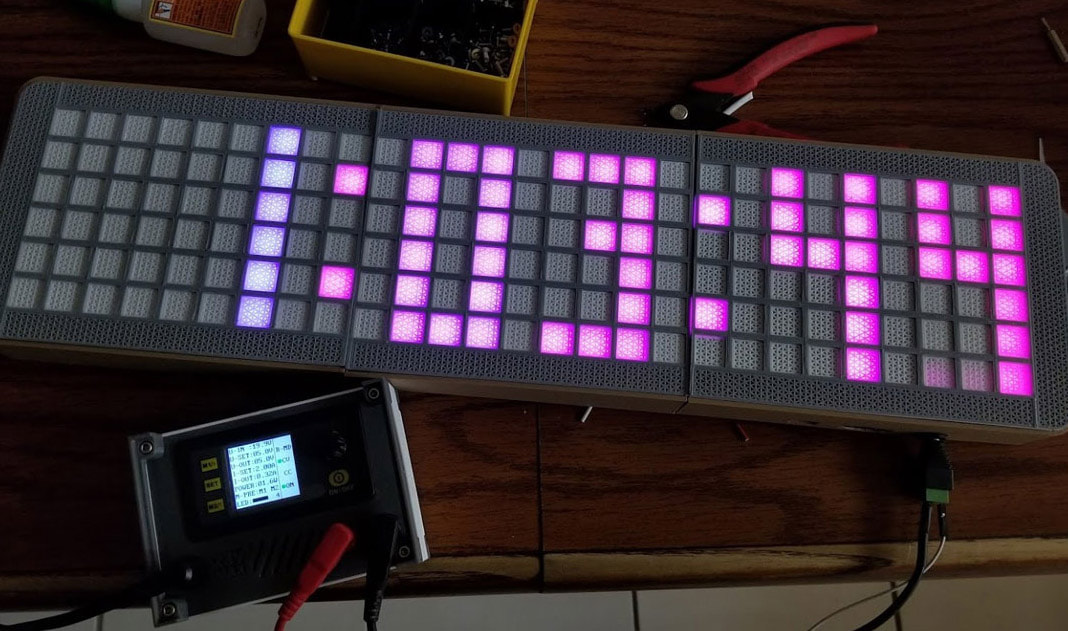
The stock code allows the brightness to be changed and also has a bunch of cool color combinations which can be cycled through, but they all appear to be static. It would be cool to get some animated wipes on the hour or other animations. I went with the Ardunio Nano version of the model, but I did design and test a base to hold a NodeMCU as well, and that may have more options for adding things like weather or other data to the display - but that is not something I plan to do since it's beyond my skill level.
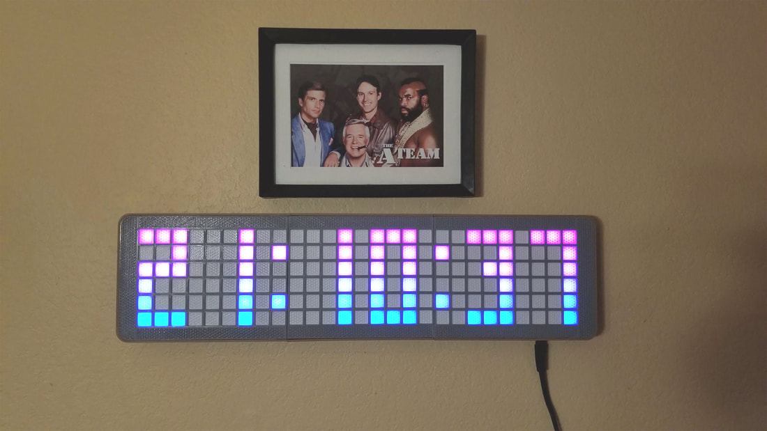
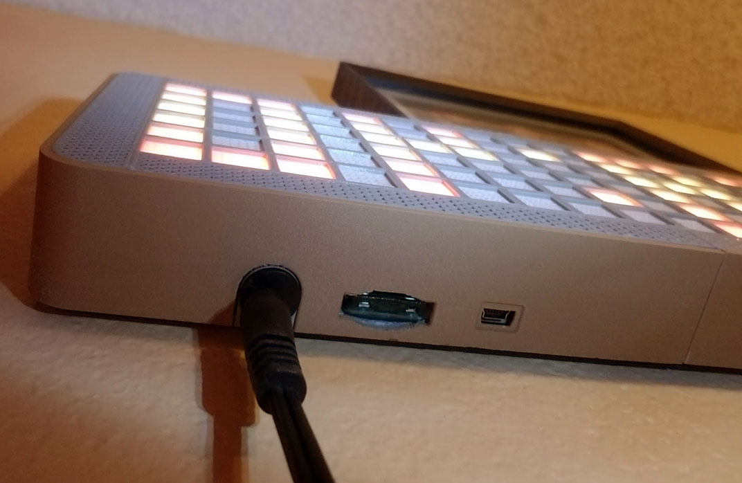
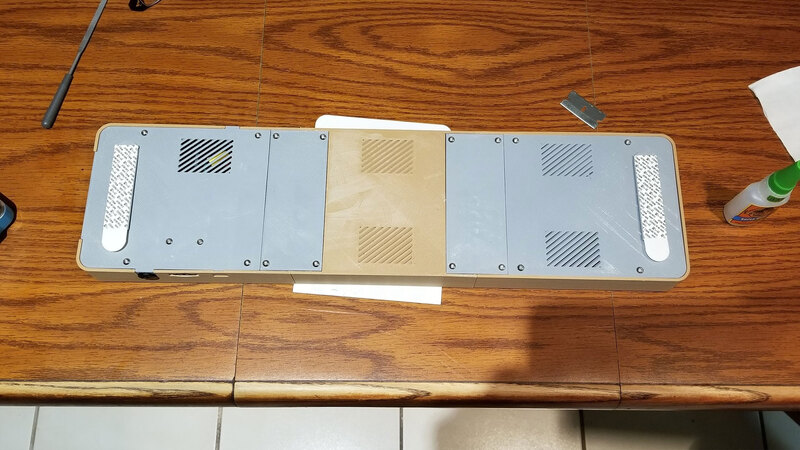
The clock was mounted on the wall using some printed hangers and 3M Command Strips, and I'm waiting on a white extension cable since the black one has too much contrast to the wall and I want to see if it can be routed a bit better. Aside from any work on the code (which I am very rusty with so probably won't happen), it's done though, and I'm pretty happy with it.
Update 2/14/2021: The Grid Clock Remix is completed and posted here.


 RSS Feed
