|
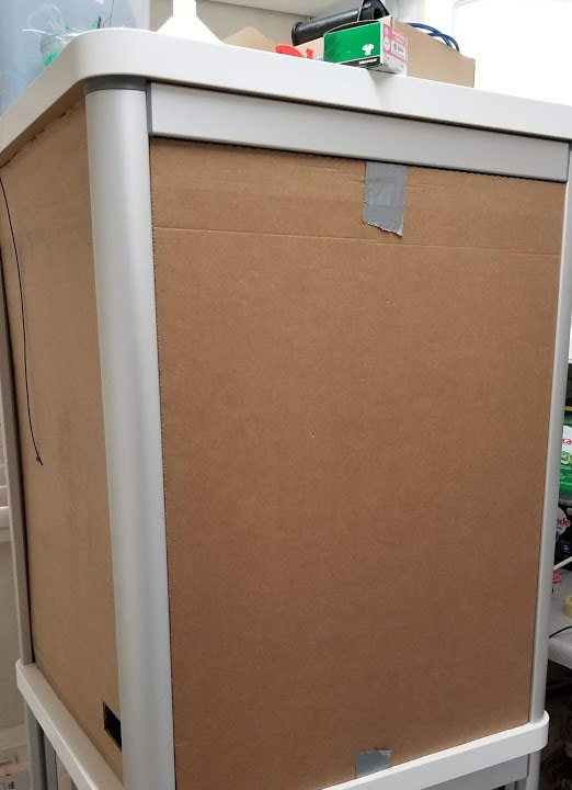
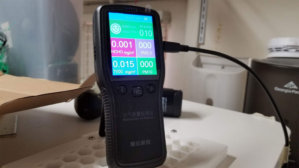
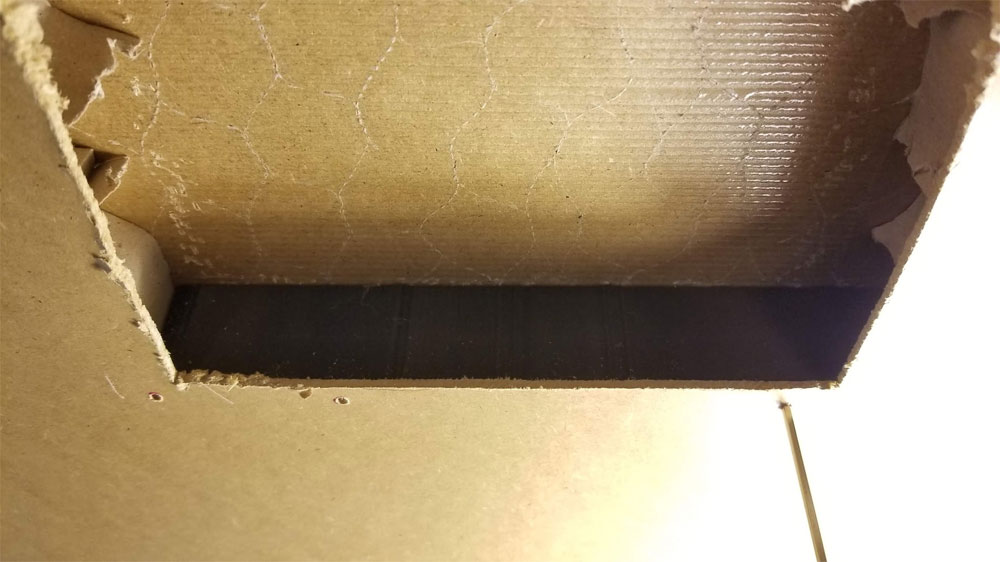
I used up the boxes that my Ikea tables arrived in to enclose the CR10S Pro, which will let me see if I screwed up on my design, and test out the scrubber. It is pretty crude right now and things are tight in there, which makes me certain it will need 2 doors and not one. I cut a small hole (very unscientifically) in the side to allow air to flow into the enclosure, and therefore be sucked back out by the scrubber. I can feel a slight airflow in, and a very good flow out, probably due to all the gaps. My plan now is to test that temps don't go nuts inside the enclosure, and that it keeps any smells down. So far temps are seem reasonable. Once the bugs are worked out I can start printing the doors and back panel in PTEG. One side will be made from an Ikea cabinet door which fits perfectly in the side openings.
0 Comments
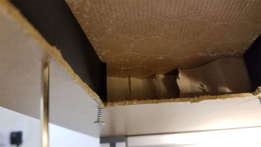
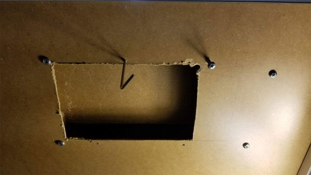
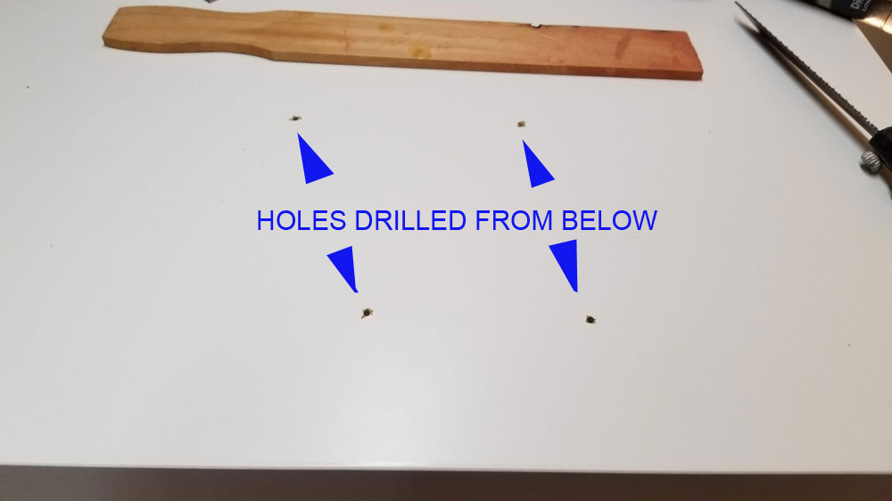
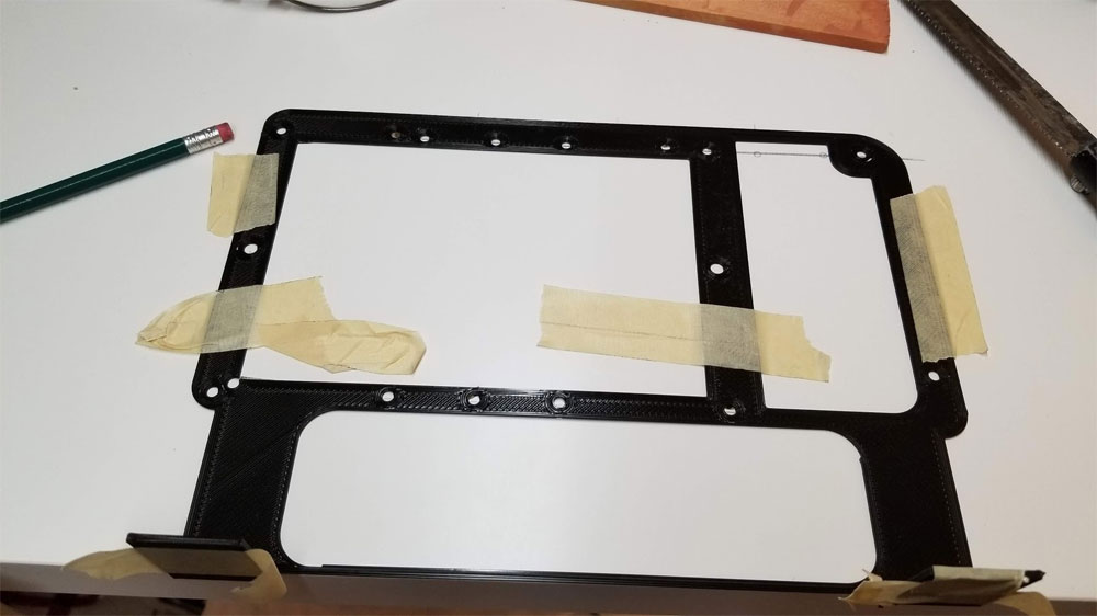
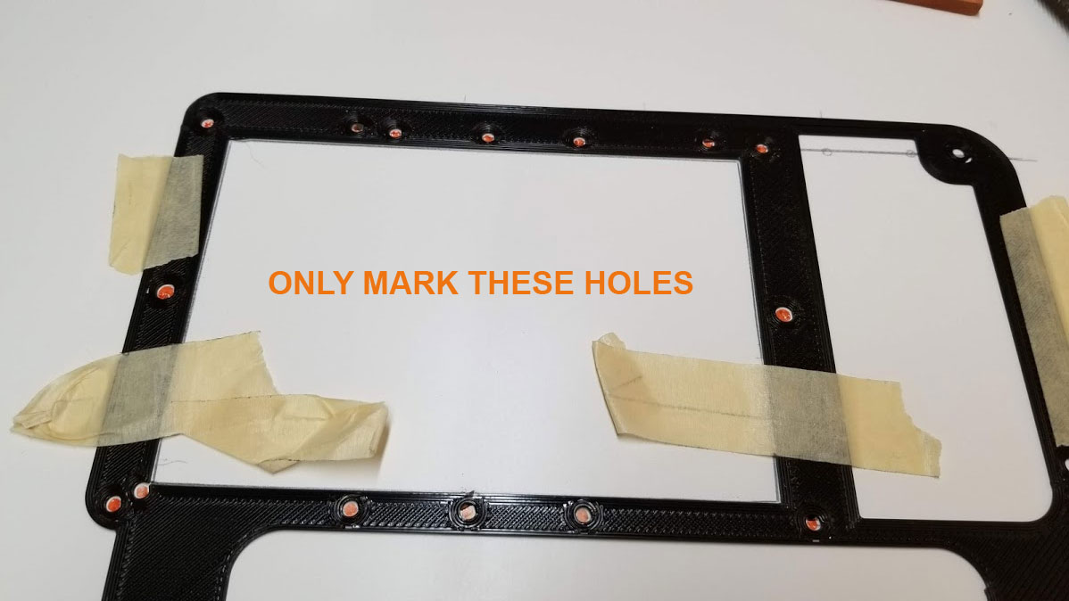
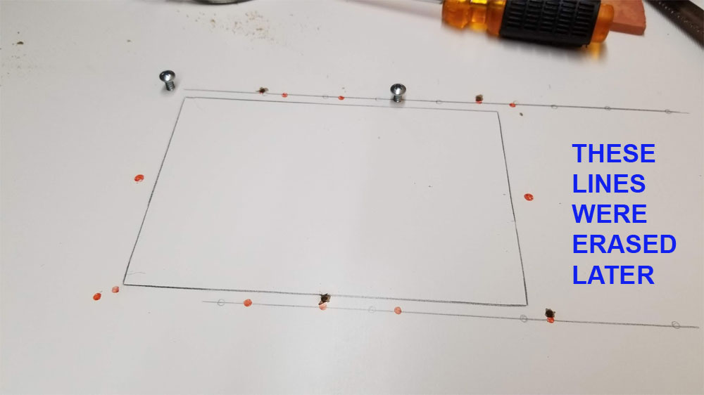
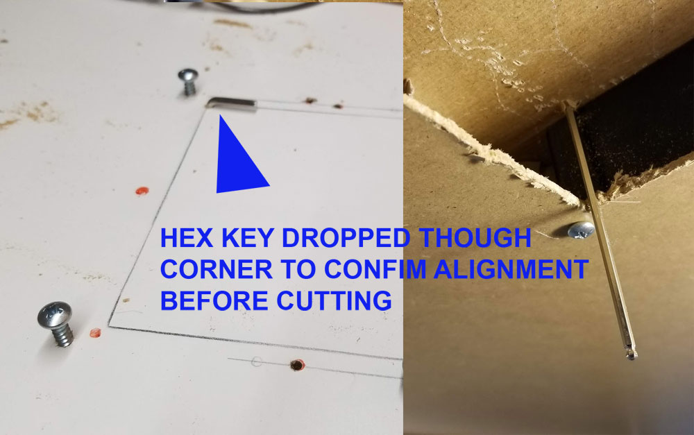
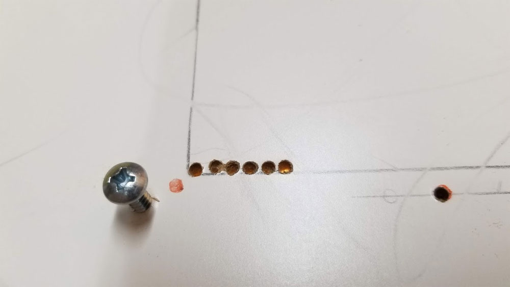
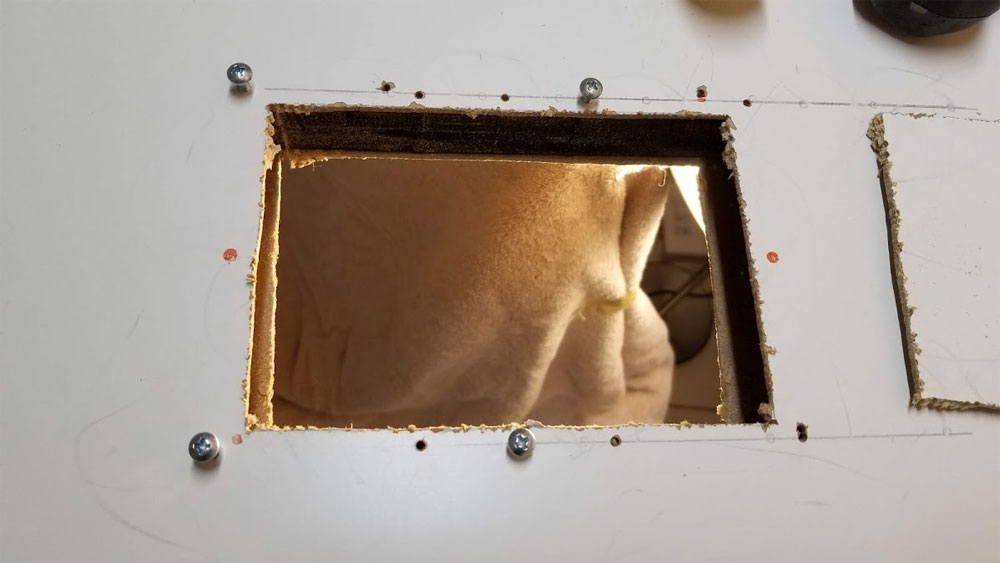
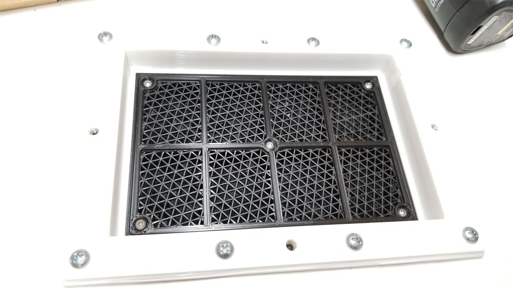
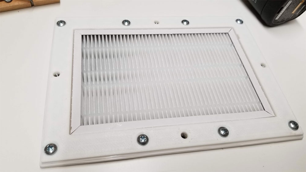
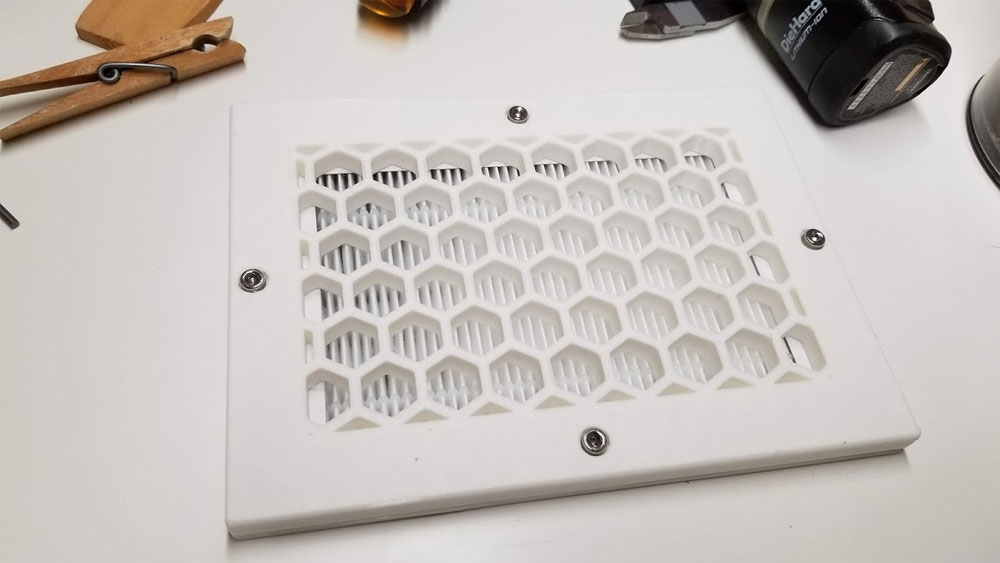
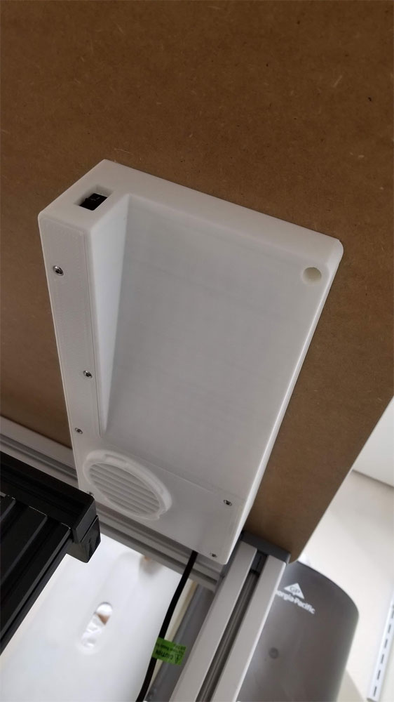
The Air Scrubber is finally installed, which required cutting a hole in my "enclosure". Fortunately my template and a bit of care in aligning things helped me get the hole in the right place. The hole had to be cut from the bottom and then the top separately, and I used some plastic bolsters which I printed to help with the alignment. The pics below show the process. There are two plastic bolsters which were installed inside the hollow top of the enclosure, which both gave me something to drill into and also assisted in aligning the template when I had to move it to the top to cut that hole.
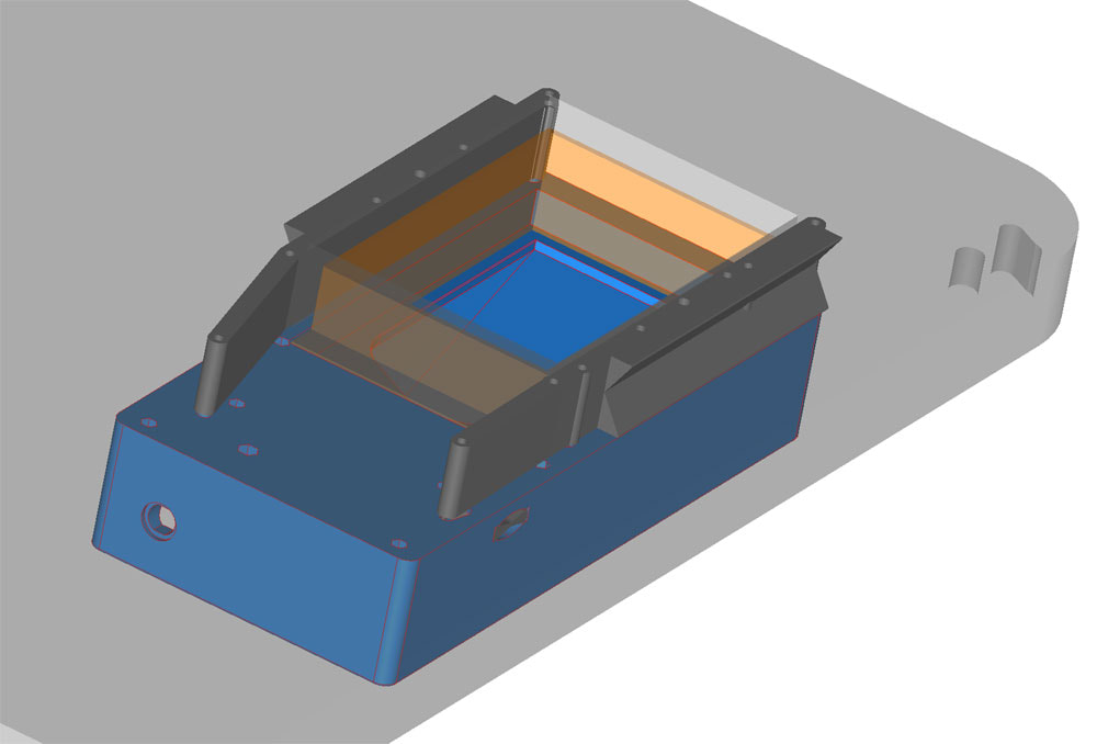
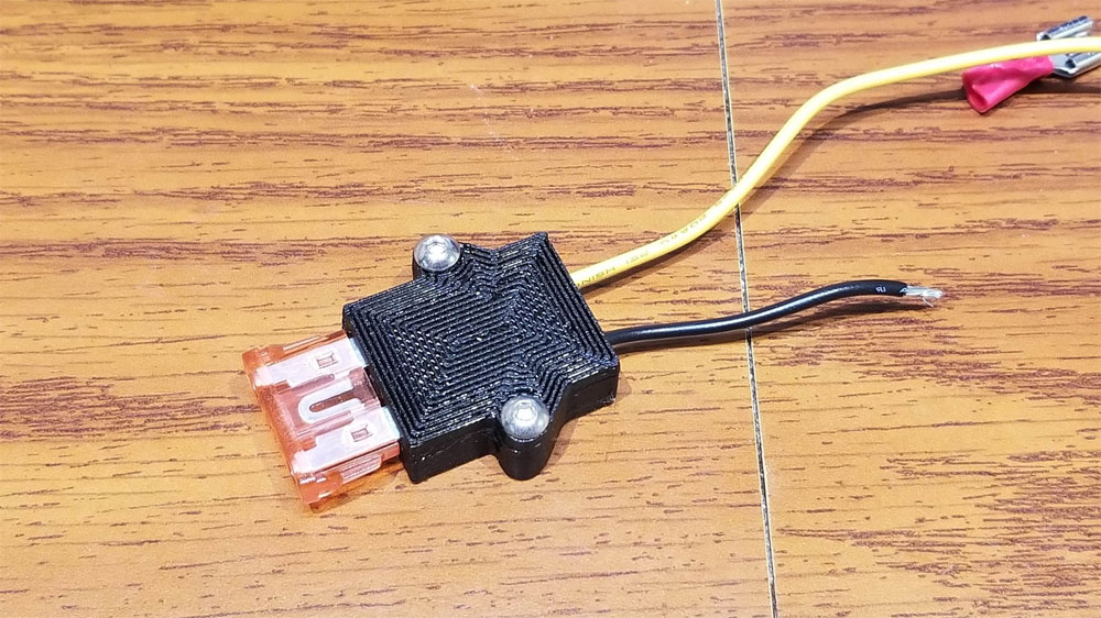
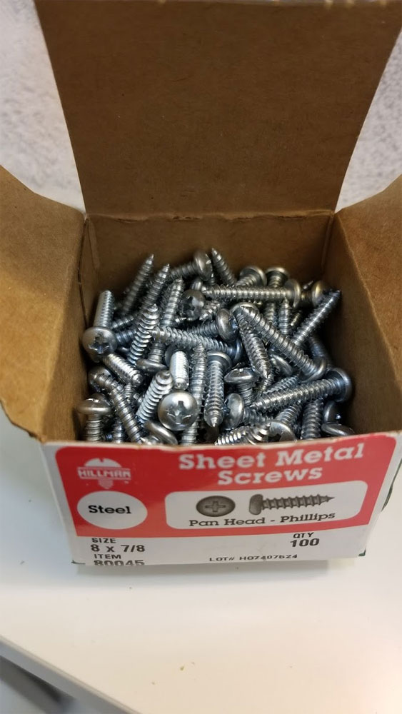
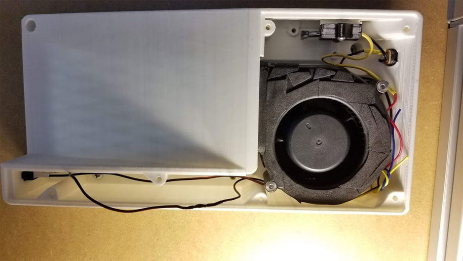
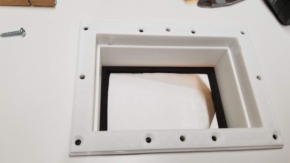
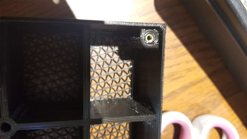
The process was to set up and mark the opening in the bottom of the enclosure top, using the template which has some tabs on it to assist in getting it parallel to the side. Then I drilled the holes for the bottom, cut the square hole, and ran some screws though and a couple additional holes which actually go on top, but I used those to align the bolsters and hold them in place from the bottom. Once I was pretty sure the bolsters were in the correct position, I drilled (from the bottom) though just a few of the holes that will be used for mounting the top. Those holes then helped me to align the template to the top, though it was not perfect. I found that the holes drilled though from the bottom were a few mm off so I used the template, which was aligned to the edge, and drew some lines in pencil which I was able to use to then align with the drilled holes. Once I knew where the template should go on top (using the drilled holes from below, and the template itself, which was parallel to the edge of the top of the enclosure), I marked out the holes that would be needed for the top, and the square cutout. The rest was the same process as cutting out the holes from below. Once the holes cut on the top, I mounted the scrubber from below. There is one mounting screw location in the scrubber which is inaccessable since the fan covers it, so I had to widen that into a key. The scrubber was then mounted from below using four #8 7/8" screws which went though the board material of the top, and then into the plastic bolsters. Next the top was attached which required a bit of cleaning up the cut edges of the top with a razor blade. I added some 1mm thick neoprene gasket tape to the underside of the top to assist in sealing (this was also used inside the filter in several places to assist with sealing). Finally the carbon filter, then the HEPA filter were installed, followed by the lid, which is held in place by four M4 cap screws. I have it connected to a 12v 3A supply and from prior testing it pulls less than an amp and is not obnoxiously loud. I added a 2A fuse on it and my updated model has the fuse integrated in the design using a fuse holder available at thingiverse - which was posted there by sk8rjess and originally created by Erik Cederberg (https://www.youmagine.com/meduza) and made available under the Creative Commons Share Alike License. I am still testing this and can tell that it will move air, there is a slight breeze from the filter when I put my hand over the exhaust. I do not have my "enclosure" enclosed however, so I have yet to test it in the application I intended it for. The hose idea, which was to use a C-PAP hose to pull air from around the hot end and filter that directly does not appear to have enough suction, but it is an idea I may come back to later (thinking of doubling the hose up for more cross section). I plan to post this up to Thingiverse when I am comfortable with the design and have run it for a bit. Update - here it is. Full Instructions here. I only know a bit about George Washington's history from reading a few books, and recall hearing of his "Fort Necessity" and the Jumonville fiasco in college History. At the time I thought the instructor was more into alternative history, and maybe a little eccentric (he once described how he dealt with a neighbor who thought she was a witch by placing a mirror on his front porch). But it turns out, my history teacher's critical view of Washington's early military efforts may have been closer to the mark. I suspect that Washington was lucky in that he survived his early (and later) mistakes, and learned enough from them to outlive his opponents in the end. It is also pretty clear (from the piece linked below) that in the pre-opening days of the French and Indian War, he had the courage and ability (though maybe not the best strategic judgement at the time) to lead his command in an endeavor that was to take him far from his bases of support, being almost totally reliant on his Indian Allies (who he did not seem to have the best relations).
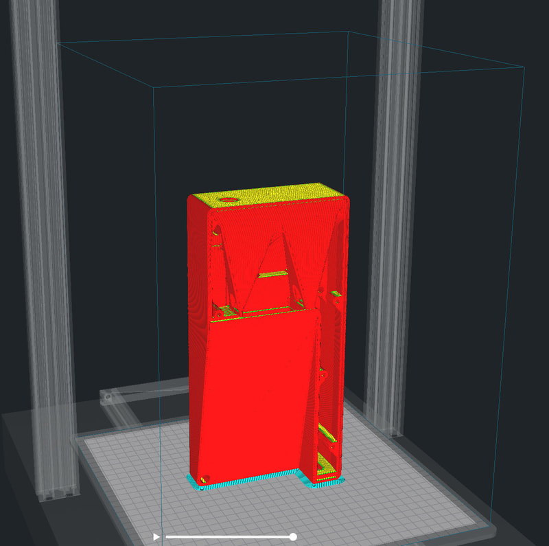
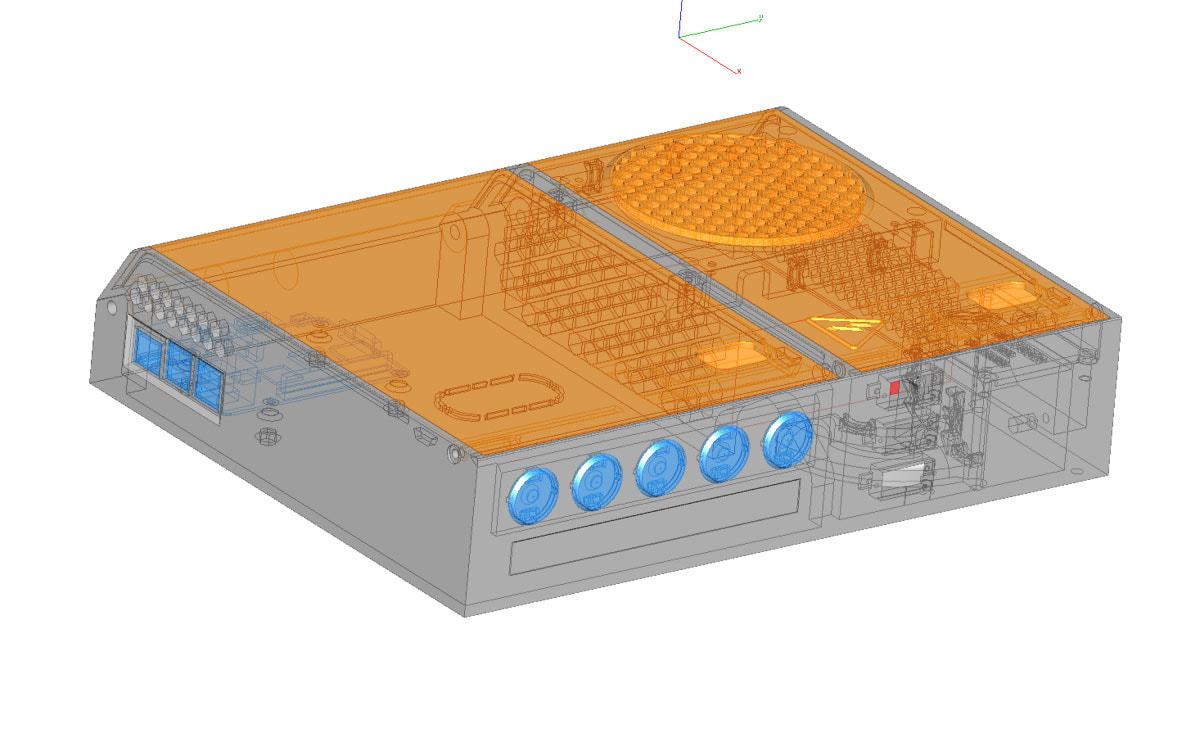
Although he failed on his first mission in a way that, by itself, left his mark on history, he was still brought along on the follow up expedition - which also failed, but it ended up further cementing Washington's reputation as a leader. Below is the link to the piece, which is an interesting read (really makes me want to buy the book they are pushing). "When Young George Washington Started a War" at Smithsonianmag.com Things are moving slowly on the 3D printer enclosure simply due to the big prints and the process of prototyping. I am loathe to waste filament on minor improvements so will probably be running with the v1.0 stuff on my own printer while the designs that eventually get uploaded will have the improvements - though some will be untested. Anyway, I decided that instead of using a 12V power supply and a buck converter for the 5V stuff, it would be better to get a dual 12v 5v supply, and fortunately I found one from Meanwell which has a good reputation for PSU's. It is the RD-65A which can supply 5v @ 6A (30W) and 12V @ 3A (36W) making it ~65W in total. It is about $24 at Amazon and cheaper on Ebay and most important, it is small. My plan is to put it in an enclosure with a fused 110 AC outlet (which will be enclosed in it's own covered comaprtment, a 6 position 2 input (5v and 12v) fuse block, some illuminated rockers, a Raspberry Pi, and a thermostatically controlled PWM fan to cool the enclosure. It will also have a pair of LCD voltmeters to monitor the 12V and 5V feeds from the RD-65A, and possibly a temp sensor as well. Right now this is the rough draft and will be updated with correct mounting holes and a few other odds and ends. This will take up much of the bed on my CR10S Pro in order to print. Version 2:
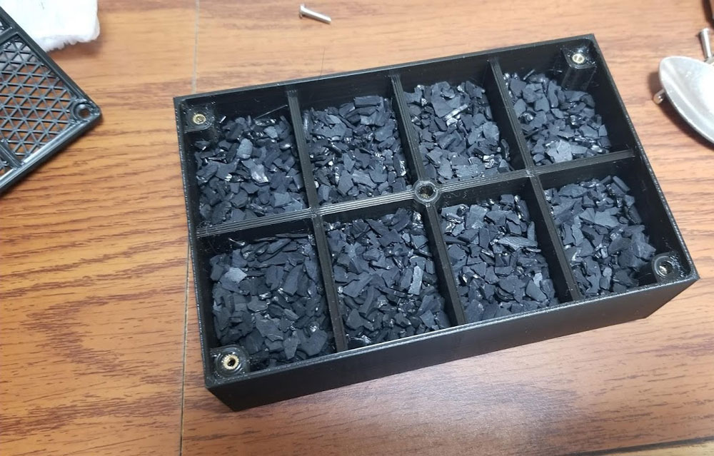
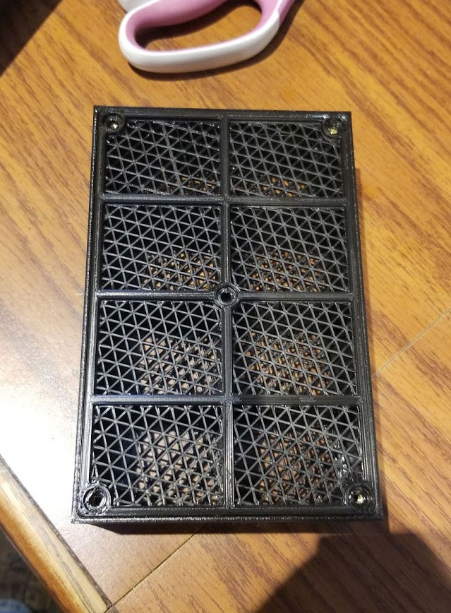
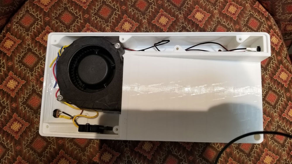
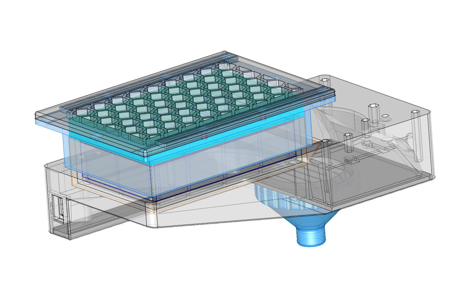
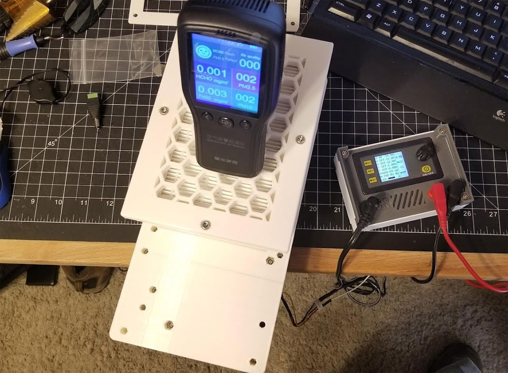
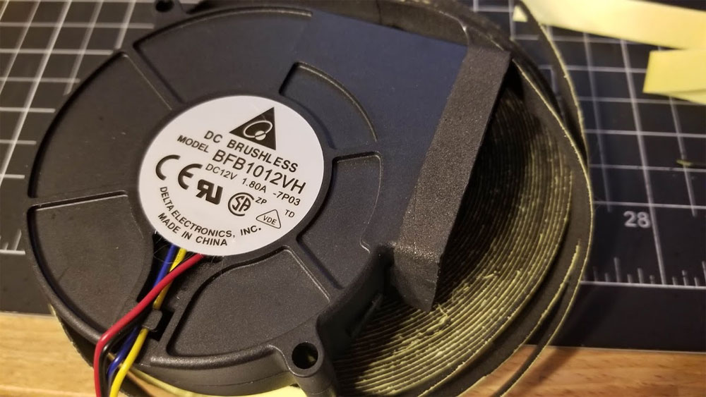
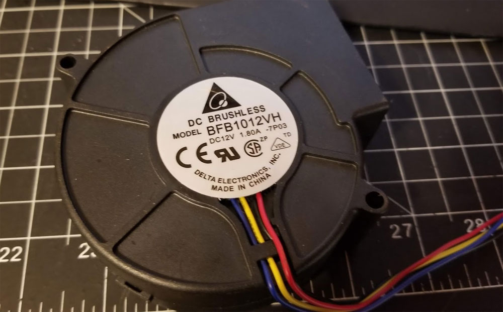
The Air Scrubber is almost done, I am just testing it before it is installed in the "enclosure". So far it is working great though on my desk. The blower puts out an impressive volume of air and although I had planned to control it using PWM, it seems to be running just about where I would want it when simply connected to 12V (red is +12V and black is Ground), so I think PWM is not necessary. Running full open at 12V it only draws 750mA so it could go higher if needed - but that would require PWM control since I don't think it runs at full tilt otherwise (could be wrong but it is rated at 1.8A and it is not pulling close to that). I filled the carbon filter box with some activated carbon pellets made from coconuts which is the way to go I think. Some activated carbon comes from bituminous coal, so I thought it best to steer clear of that for this project. Above the carbon box is a HEPA filter and the airflow goes from fan > carbon > HEPA. I know this may not be the way many filters work, but I wanted the HEPA to filter any fine particles from the carbon filter before exhausting to the room.
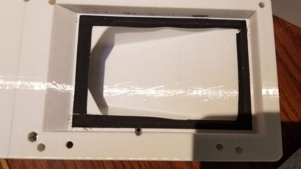
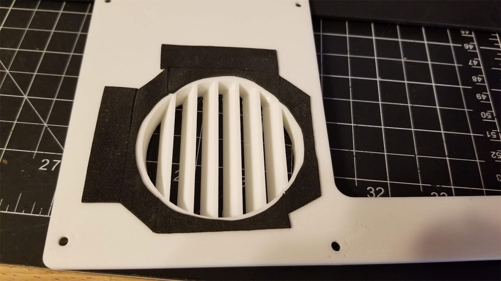
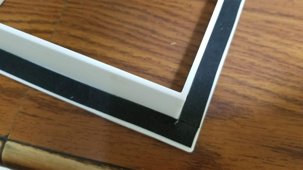
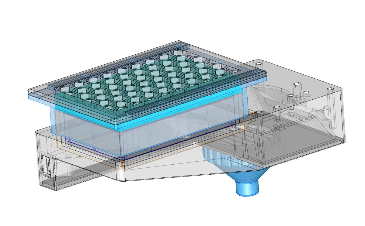
The black tape is 1mm neoprene gasket tape which I used to help seal between the filter body and the carbon tray, and avoid leaks, which seems to be working well. I did not detect any leaks around the body of the filter so all the air seems to be moving through the HEPA (and I can feel the airflow though it also). The funnel like thing in the 1st pic is an adapter for a CPAP hose, which, when connected still has some mild suction at the end of the hose - though the hose is over a meter long and will be cut down in the final application. I am still not sure if I will use the hose, but want to try it out as a point filter. I should have some pics of this installed and set up soon. I'm still working on the enclosure for my CR10S Pro, but decided to make the Air Scrubber now since I think I may be able to use it without the enclosure (for the time being). The scrubber will use a HEPA filter for a vacuum cleaner and some granulated activated carbon made from coconut shells. I have seen several designs for scrubbers but for some reason they place the filter before the carbon. This filter will have the dirty air pass through some carbon granules and then through the HEPA filter before being exhausted. I am going to try to use a CPAP hose to suck the air from around the nozzle which I suspect could help keep the particulates down, even without an enclosure. The base is printing now (it is a 26 hour print), using a 0.6mm nozzle.
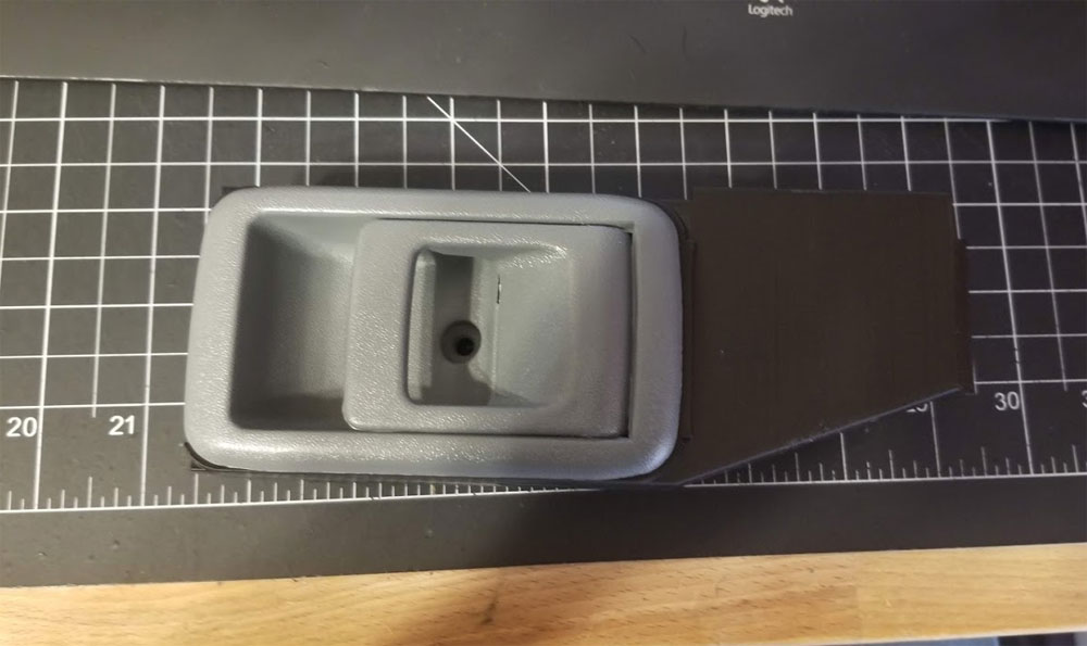
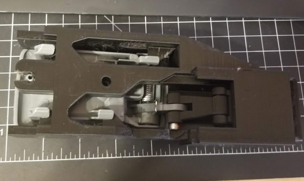
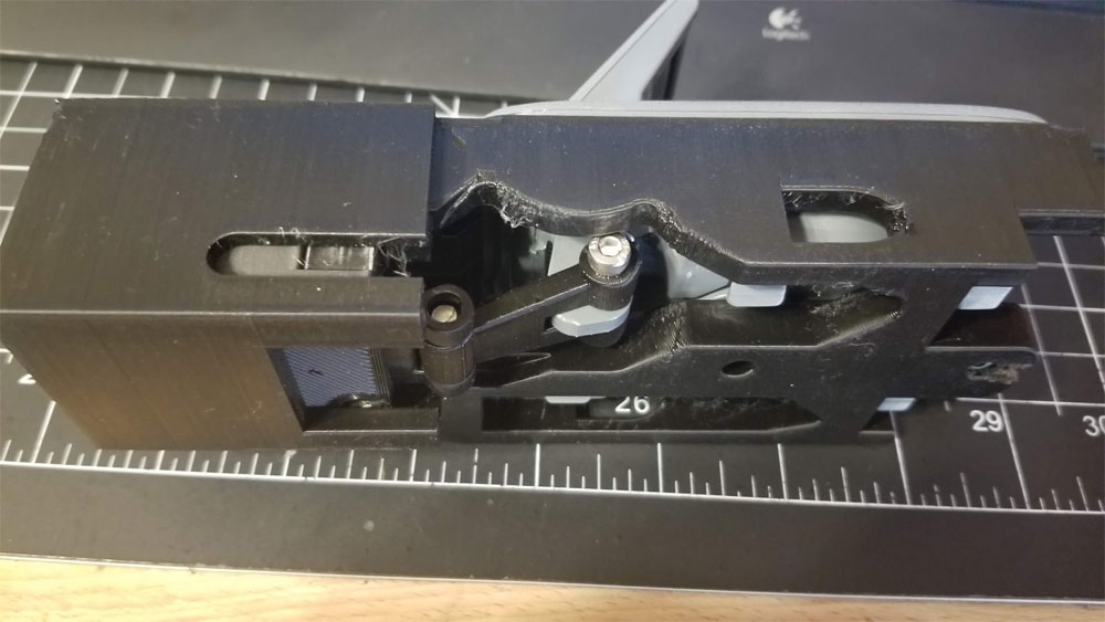
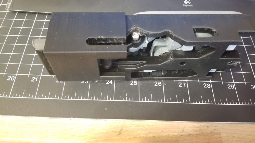
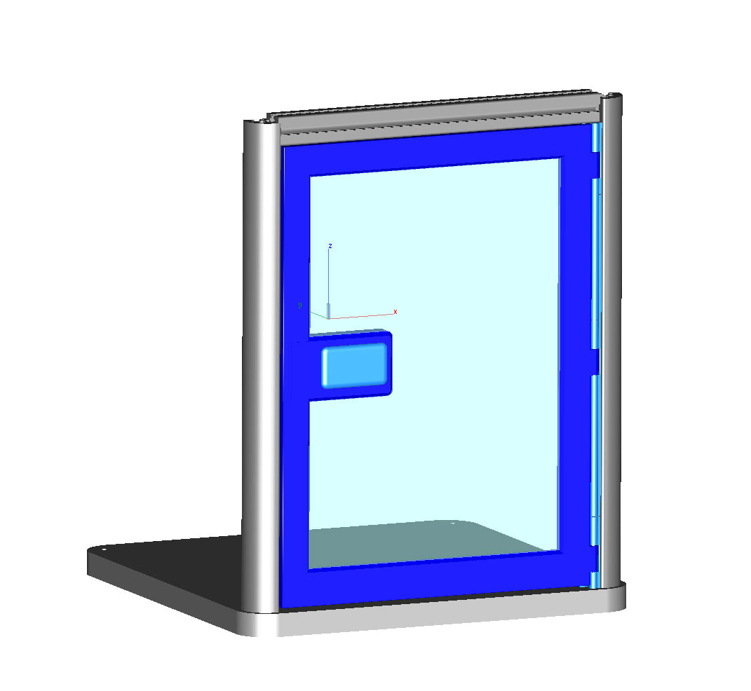
I am building a door (two actually), for my CR10 enclosure, and so I need to have some sort of door latch. I had started designing a latching mechanism and then thought, why not use an interior door latch from a Jeep, which is a pretty basic door latch. When I started poking around on Amazon, I found something possibly better - a door handle from a Toyota 4Runner (and some other vehicles). It is a bit big. but I think it will work. I just had to model the handle (roughly) and design a mount for it. The mount shown above is designed to help me finalize the design, but it works (roughly). The way it works is the stock door handle moves a part which connects to a block (which has a spring in it to allow it to be closed without opening the door handle). When the door handle is opened, it moves the connector to the right, which pulls the block out of the way and allows the door to be opened. To close the handle moves the connector to the left which pushes on the sprint loaded block and pushes it into the hole in the door sill which latches the door closed. It is a bit thick, but I don't think it will be too ugly looking.
|
Stoopid MeWelcome to my Stoopid corner of teh Internet. It's mostly gonna be 3D printing stuff, but I also post some recipes, projects, and the occasional rant here as well. More Stoopid stuff is updated regularly. Archives
July 2024
Categories |



 RSS Feed
