|
The prior version did not work so great, the fan duct sat too low and the way it attached allowed it to sag. This will hopefully correct those problems. I hacked up the fan duct from here to create the part.
0 Comments
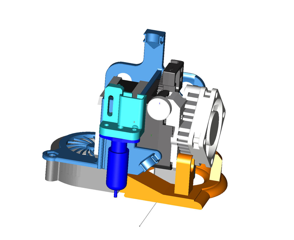
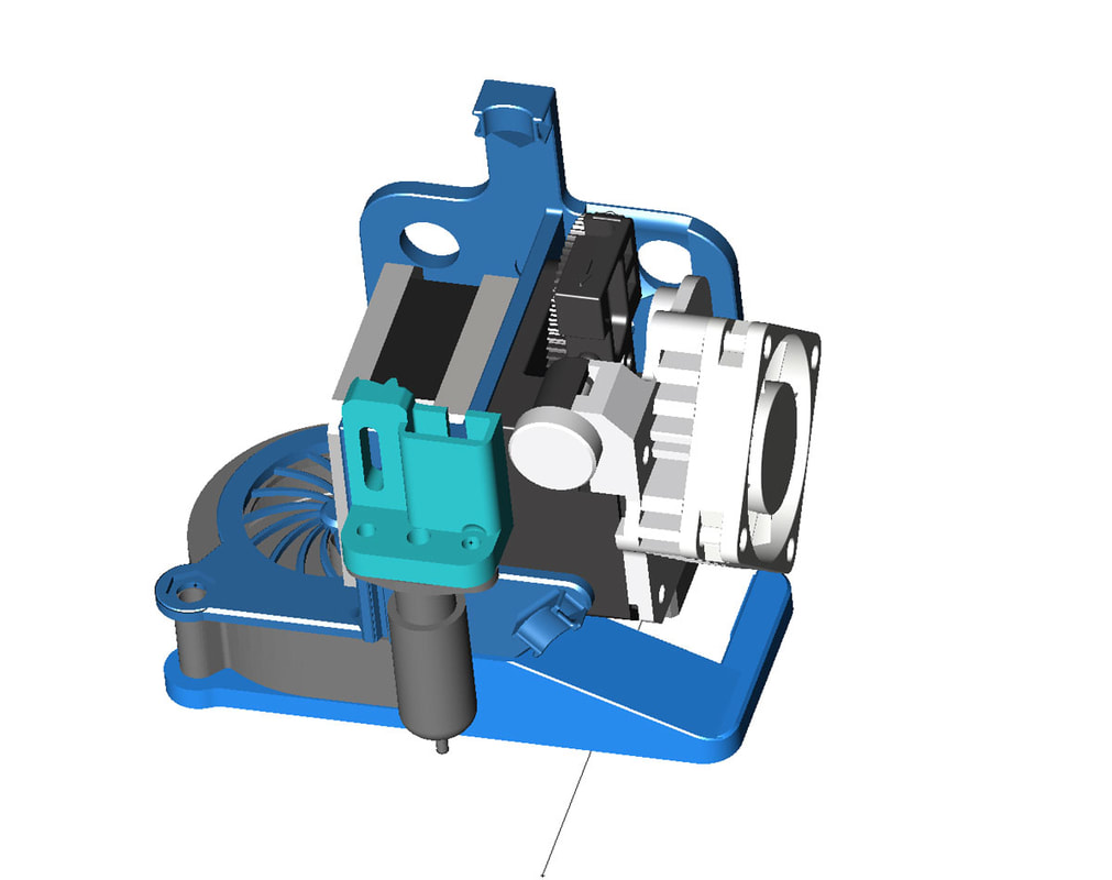
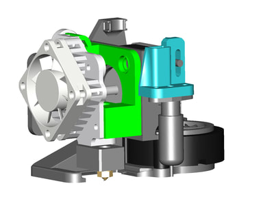
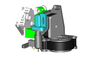
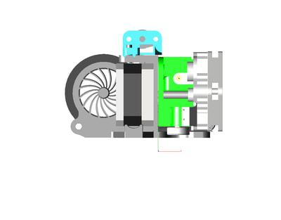
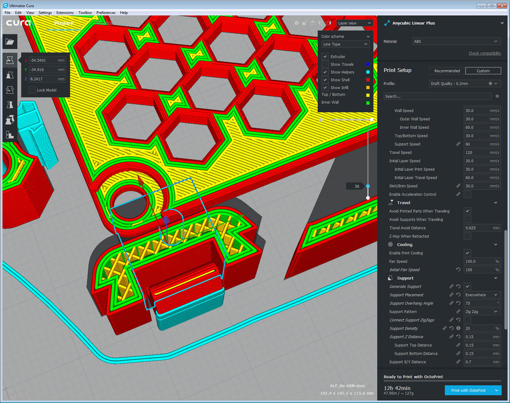
The prior version was still wasting too much of the build volume, so hopefully this version will fix that. I flipped it back to the more conventional setup and put the nozzle in line with the stock nozzle location. The fan is still undermounted which will allow me to use a more powerful stepper or put a heatsink on the back if I want. This is printing right now.
These are just some recommendations for folks that solicit free help with their PC, phone, Internet, TV or whatever...
The Ender3 has been a big pain to get functional, but I am going to get it working one way or another. I have thrown a lot of time at it already so now I have to throw some money at it as well. Cheap never seems to be inexpensive in my experience, but I don't ever learn. Anyway, I am upgrading the Ender with a Titan clone and a Titan Aero. I found that not all Titan clones are made equally and the one I bought is just slightly different than the original. On it's own the Titan clone works, but when I bought a Titan Aero heatsink which was built to the original spec, nothing fit (well almost nothing). I found that the base of the clone Titan had things shifted so when joined with the Aero the holes did not align. I found however that I could print a new base for the Titan which was to spec and that solved my problems with the cheap clones (I used the base from here).
Once that was sorted out, I needed a base for mounting everything. There are tons of great mounts to choose from, and I modded one that worked well. But decided that I wanted something more compact so I would not lose as much of the build volume. I also wanted to be able to add a larger stepper or a heatsink on the stepper. I rotated the Titan Aero clone 180 degrees from most mounts and raised it up a bit to allow the thumbwheel to be used. There are only 2 parts to this mount and hopefully it can be printed without internal supports. This is the result and it is printing now, I will upload it to thingiverse once I get it all tested. I saw this today, which I hope is the beginning of a wave of these verdicts. I don't normally cheer for lawyers, but in this case, aside from the justice being conveyed, it may be the only way to bring some free market regulation to bear (since it is clear that the gub'ment ain't gonna do it). And yes they will appeal it, but hopefully this verdict, probably (unfortunately) not the scale of the award, will stick in the end.
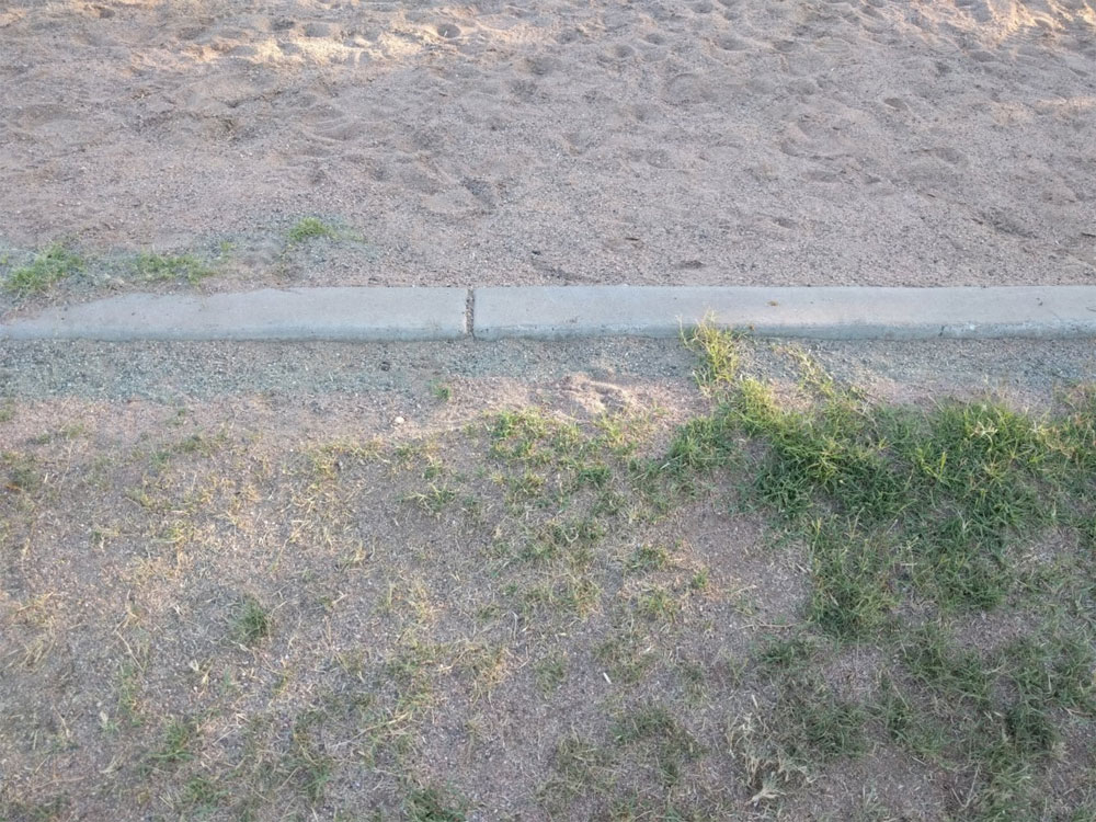
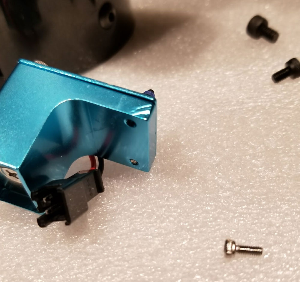
Ranger Pro is sprayed at the parks where I used to take my dog (RIP Sunny), and I see kids and families playing there all the time so the use of glyphosate in these places is concerning. What peeked my concern about it was when I found there was a study that linked herbicide use generally, to the same TCC cancer my dog had (the study monitored Scottish Terriers which are most susceptible to TCC). That study however said that there was no "significantly associated with risk of TCC" for dogs exposed to lawns or gardens treated with nonphenoxy herbicides. After reading up some more, they classified glyphosate as an amino acid type herbicide which would fit in the "nonphenoxy" category. The study had only 6% of the case dogs (dogs with TCC) that were exposed to glyphosate only, and only one control dog that was exposed to glyphosate only. With so few dogs in that study with exposure to glyphosate specifically, it seems like it neither adds or takes away. It does seem wise however to keep people and pets out of areas freshly sprayed, the problem is that there is no posted signs at parks to say when they have sprayed. I also think that it is over used in place of mowing or just being applied to places without considering the need for it. The pics below are from last year, when I was still taking my dog to the park, and show it was applied on dirt which was pointless. Fortunately my City is receptive to taking another look at this situation and it seems things may be moving in the right direction. marlinfw.org/docs/configuration/configuration.html#safetyI wanted to add some notes (in one place) on the initial setup for my delta in case I need to refer back in the future. These notes are from my notes and memory, and of course I did not come up with this myself but unfortunately I don't have the links for the many places this info was gleaned from (if I find the links I will add them here for reference). This is all done after the firmware upgrade, when the printer is fully functional and end stops are all confirmed to be working. The last part utilizes a z-probe. I am by no means an expert on this, and I still have some questions on the ideal calibration temp to use if the plan is to run PLA and ABS as I do, but I used the following. This assumes a standard configuration where the heated bed, nozzle and hot end fan are connected correctly and Marlin is set up correctly for the board. Like all info on the Internets, take it with a grain of salt - and verify it for yourself. Before anything is calibrated, I checked the endstops and that temps are reporting: Checked all the endstops using M119: Send: M119 Recv: Reporting endstop status Recv: x_max: open Recv: y_max: open Recv: z_min: TRIGGERED Recv: z_max: open Recv: ok Triggered is just what it means. I went through and triggered each end stop manually, to confirm they were connected and working. I found though this, that I incorrectly inverted the logic on the Z-Probe (which is on Z-min) so I had to go back and fix that in Marlin's configuration.h and re-load the firmware. below is the corrected config: // Mechanical endstop with COM to ground and NC to Signal uses "false" here (most common setup). #define X_MIN_ENDSTOP_INVERTING false // set to true to invert the logic of the endstop. #define Y_MIN_ENDSTOP_INVERTING false // set to true to invert the logic of the endstop. #define Z_MIN_ENDSTOP_INVERTING false // set to true to invert the logic of the endstop. #define X_MAX_ENDSTOP_INVERTING false // set to true to invert the logic of the endstop. #define Y_MAX_ENDSTOP_INVERTING false // set to true to invert the logic of the endstop. #define Z_MAX_ENDSTOP_INVERTING false // set to true to invert the logic of the endstop. #define Z_MIN_PROBE_ENDSTOP_INVERTING false// set to true to invert the logic of the probe. I also checked the temp probes were reporting in Octoprint. Running the PID calibration for the hot end - gcodes: PID tuning is done to optimize the heat up time for the bed and nozzle. These can either be configured in the configuration.h in Marlin before compiling, or set in the EEPROM after the firmware is loaded using gcodes. Since adding them to the conifguration.h is not possible until the printer is running the firmware, I think it is simpler to just do it afterwards using gcodes. If I were to upgrade Marlin later, I would just add these to the configuration.h since I have the values now. PID values are specific to each printer, so even though a printer may be the same model with all the same components, the PID values will be different. I monitored the temps when running PID tuning to make sure the correct temp probe was reporting the temps expected (so if tuning the bed, I made sure the bed temp probe was reporting the higher temp), and then the same for the hot end. I also allowed things to cool down between running the bed and nozzle calibrations. This confirmed that the temp probes were correctly set up and not connected to the wrong places on the board. This is how I ran the PID AutoTune, so use this info at your own risk. If you have issues with your printer maintaining temps, I suggest checking that the thermistor is not loose/damaged/broken, and is making good contact with the block before changing PID vales. Not directly related to PID, but please be aware that some older Versions of Marlin firmware DO NOT have Marlin's Thermal Runaway Protection enabled. Some factory installed firmwares are also using older verisons of Marlin which are missing Thermal Runaway Protection. It would be a good idea to update to newer firmware which has Thermal Runaway Protection, on a printer that does not have it. Bed: M303 E-1 C8 S90 Explanation: E-1 = Bed C8 = run the test for 8 iterations S90 = run the test at 90 degrees C Recv: bias: 129 d: 125 min: 89.74 max: 90.25 Ku: 632.41 Tu: 22.26 Recv: Classic PIDR ecv: Kp: 379.45 Ki: 34.09 Kd: 1055.81 Recv: PID Autotune finished! Put the last Kp, Ki and Kd constants from below into Configuration.h Recv: #define DEFAULT_bedKp 379.45 Recv: #define DEFAULT_bedKi 34.09 Recv: #define DEFAULT_bedKd 1055.81 Recv: ok to set the values (this is an example based on the above output, DON'T USE THESE VALUES): M304 P379.45 I34.09 D1055.81 M500 http://marlinfw.org/docs/gcode/M303.html http://marlinfw.org/docs/gcode/M304.html Nozzle: M106 S255 M303 E0 C8 S200 Explanation: M106 S255 = sets fan to 100% (visually check to be sure the hot end fan is turned on) M303 (PID AutoTune): E0 = nozzle C8 = run the test for 8 iterations S200 = run the test at 200 degrees C Recv: bias: 125 d: 125 min: 194.41 max: 207.14 Ku: 24.99 Tu: 29.95 Recv: Classic PIDRecv: Kp: 15.00 Ki: 1.00 Kd: 56.14 Recv: PID Autotune finished! Put the last Kp, Ki and Kd constants from below into Configuration.h Recv: #define DEFAULT_Kp 15.00 Recv: #define DEFAULT_Ki 1.00 Recv: #define DEFAULT_Kd 56.14 to set the values (this is an example based on the above output, DON'T USE THESE VALUES): M301 P15.00 I1.00 D56.14 M500 http://marlinfw.org/docs/gcode/M106.html http://marlinfw.org/docs/gcode/M303.html http://marlinfw.org/docs/gcode/M301.html For each of these calibrations, and at each step where they were set, I used M500 to save the config to EEPROM and M501 and M503 to confirm the values are in EEPROM. The output above also gives the configs that would be used in configuration.h (in bold) which could be set when Marlin is re-compiled. I am fine with keeping them in EEPROM however so won't re-compile just for this. Touch probe offset setup Before running the G33 the auto calibration, I had to set up a touch probe. In my case, the probe used is the stock z-probe that shipped with the Anycubic Kossel Linear Plus (shown below in a state of being disassembled): To set up a touch probe, the offsets need to be determined for the X, Y and most importantly the Z. Normally these can be found in the notes for whatever bracket was used to mount the probe. I set the X and Y offsets up in Marlin before it was complied (in configuration.h):
#define X_PROBE_OFFSET_FROM_EXTRUDER 0 // X offset: -left +right [of the nozzle] #define Y_PROBE_OFFSET_FROM_EXTRUDER 0 // Y offset: -front +behind [the nozzle] #define Z_PROBE_OFFSET_FROM_EXTRUDER -14.90 // Z offset: -below +above [the nozzle], Anycubic Leveling Module v1:-18.0, v2:-14.9 For my printer, the X and Y offsets are zero since the probe sits right over the nozzle (the X and Y offsets need to be integers BTW, Marlin will complain if they are floating point (numbers with a decimal place). The Z offset that I set in configuration.h was just a guess, and was not correct so I had to adjust that later. The corrected Z-offset was found by a process that is summarized as follows:
After that I ended up with a value of -15.44 which was pretty spot on. One problem that could be run into, is that the printer will just stop slightly above the bed when running the auto calibration or setting the delta height automatically - and there would be an error. I found that this happened if the Z-offset is too small to begin with (the value used in configuration.h is too small). When this error happened, I just manually set the delta height a bit taller so it would not error, until I could get everything correctly calibrated. Once the offset was figured out, I ran the delta height calibration again to set the correct value again for delta height. I think that has to do with bot the " Z_PROBE_OFFSET_FROM_EXTRUDER" being too small and the "Z_PROBE_LOW_POINT" being too small. The "Z_PROBE_LOW_POINT" is used as a soft limit to keep the nozzle from crashing too far into the bed but it is what caused the error I think (it was working as designed, I just had the values for the Z-offset too small). G33 Delta Auto Calibration Delta Auto Calibration is awesome, and worked great once the probe was set up. Running it also provides some values to be set in EEPROM for the tower angels and radius which are correction factors to compensate for an imperfect machine. There does not seem to be a set number of iterations that the calibration will run for, it just keeps going until the standard deviation gets below a pre-determined value which I think is 0.01. To run the auto-calibration I used the following gcode: G33 P7 V2 Send: G33 P7 V2 <...> Recv: Iteration : 04 std dev:0.041 Recv: .Height:274.03 Ex:-1.33 Ey:+0.00 Ez:-2.22 Radius:135.31 Recv: . Tx:+0.97 Ty:-0.26 Tz:-0.71 Recv: Iteration : 05 std dev:0.022 Recv: .Height:274.06 Ex:-1.34 Ey:+0.00 Ez:-2.18 Radius:135.41 Recv: . Tx:+0.96 Ty:-0.26 Tz:-0.70 Recv: Calibration OK rolling back. Recv: .Height:274.03 Ex:-1.33 Ey:+0.00 Ez:-2.22 Radius:135.31 Recv: . Tx:+0.97 Ty:-0.26 Tz:-0.71 Recv: Save with M500 and/or copy to Configuration.h Then I used M500 to save the values and then M501 and M503 to confirm they were set and used. They show up on the following line: Recv: echo: M665 L271.50 R135.31 H274.03 S160.00 B93.00 X0.97 Y-0.26 Z-0.71 In Marlin configuration.h, these would be set under the following (below are my settings from before the auto calibration): #define DELTA_RADIUS 134.4 //mm Get this value from auto calibrate // Trim adjustments for individual towers // tower angle corrections for X and Y tower / rotate XYZ so Z tower angle = 0 // measured in degrees anticlockwise looking from above the printer #define DELTA_TOWER_ANGLE_TRIM { 0.0, 0.0, 0.0 } // get these values from auto calibrate The following links are for tweaking the tower trim and radius by printing and then measuring a test object. It can help verify the settings based on the above are correct and provide new values to try: https://www.thingiverse.com/thing:1274733 https://docs.google.com/spreadsheets/d/1HcnZ0aDC2wujHhPHVeYFcPekEpY6Y4wLSMfCxJ18e1o/edit#gid=1292102991 Extruder Calibration Linked below is the best guide I found for calibrating the extruder steps. https://mattshub.com/2017/04/19/extruder-calibration/ It is simple to do, with one gotcha - Marlin will not allow cold extrusion by default so if trying to extrude cold just to test, it will not work. I usually have calibrated the extruder steps hot, with the hot end connected up. But sometimes I have tried to save filament because there was a problem requiring re-checking the extruder steps several times over (and I had things disconnected so the filament could just be run though). In those cases I ran into this issue. The prevent cold extrusion configs can be confirmed in Marlin's configuration.h below: #define PREVENT_COLD_EXTRUSION #define EXTRUDE_MINTEMP 170 Got an email today asking for a donation from Wikipedia, which reminded me that I use that site all the time. With no ads and supported by volunteers, it is amazing they create such a high quality and useful resource. I just wish it was around when I had to write term papers in high school (the night before they were due).
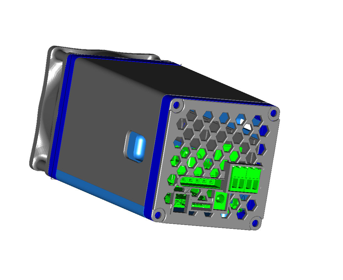
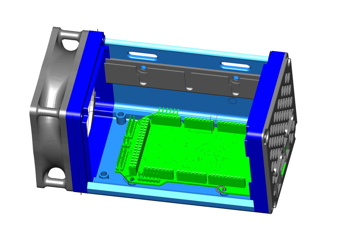
https://donate.wikimedia.org Since my printer (the Kossel not the POS Ender 3) is working again, I started working on the case again for it. I didn't like the old design and wanted something that would be easy to work on, modular and simple. Tooless would be ideal, and I wanted good airflow since I planned to use TMC drivers which run hot. This is the result (currently).
The design uses an 80mm fan which can either push or pull air though the case. The top and side swing up on a hinge and there is a latch on one side to secure it. The latch uses a spring from a cheap ball point pen which has just the right amount of force. Since the case is low profile, I had to use M3 and M4 inserts on it, which are not something most people have around, but that was the compromise since if I had used nuts instead it would have been larger than I wanted it to be. I have only printed parts of the case to test various things and am printing the design now. I've made a face plate for both the RAMPS 1.4 (shown) and a more generic plate which I plan to use on my RAMPS 1.6. 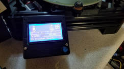 The Kossel seems to be back in business* (given it's history I cannot say this 100% confidence), but I am hopeful. The first print off the machine since the fixes looks decent. So I still have some things to work out, but they are pretty minor and just require some re-wiring. Most of the following info is from memory, but will try and lay out a general outline of what was needed to get the Re-ARM working with a RAMPS 1.6 (should be the same for RAMPS 1.4 or 1.5 also), for my Anycubic Kossel Linear Plus (Delta). One of the most difficult things to get done was compiling the Marlin firmware using Atom. It is not as user friendly as the Arduino IDE and requires a good deal of backtracking when there are errors. This is really just a re-hash of the info found in the following links which I am also referring to below: http://marlinfw.org/docs/basics/install_rearm.html http://marlinfw.org/docs/basics/install_platformio.html http://docs.platformio.org/en/latest/ide/atom.html#installation Firstly though, here are some limitations with the Re-ARM to consider, none of them caused me any serious issues though (yet).
P1_30 (37) - not 5V tolerant P1_31 (49) - not 5V tolerant P0_27 (57) - open collector P0_28 (58) - open collector
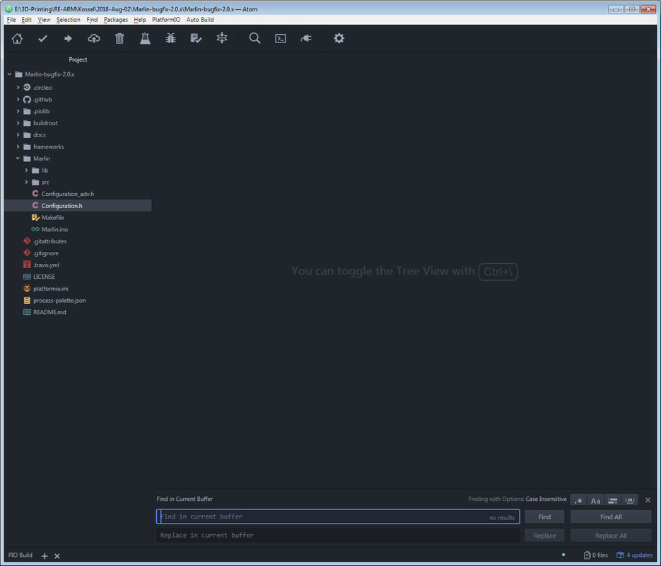
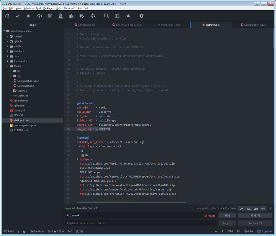
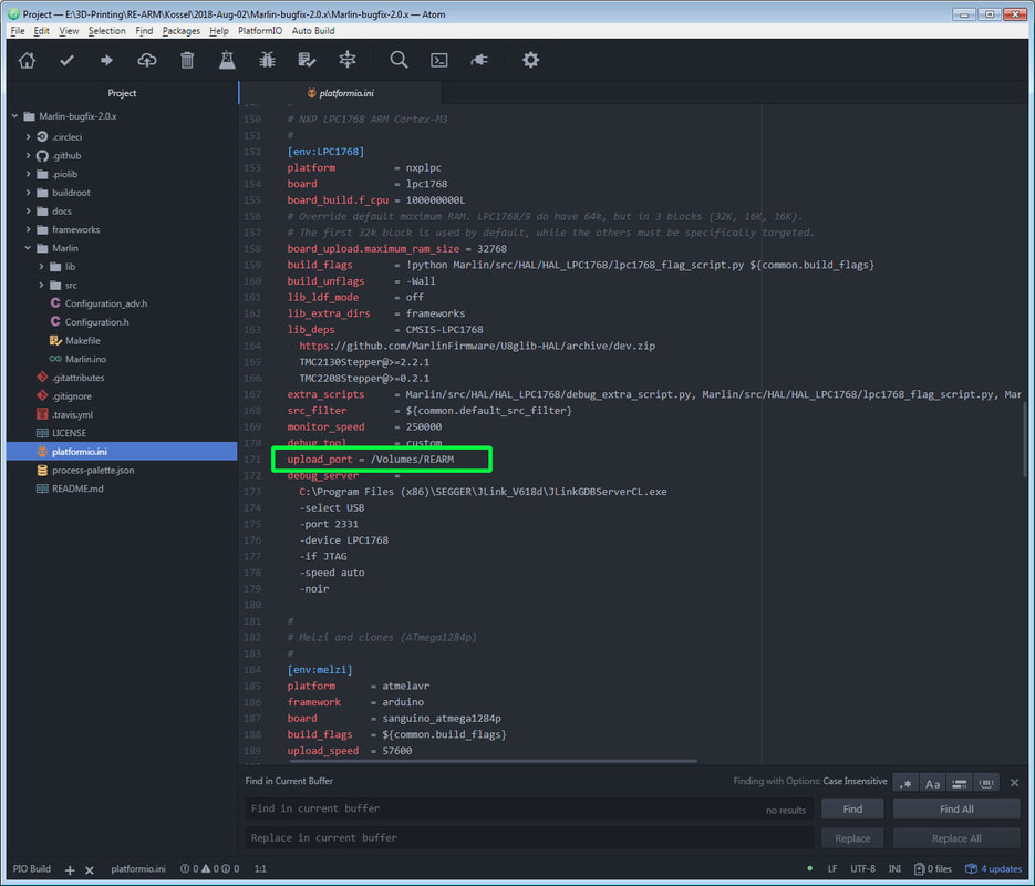
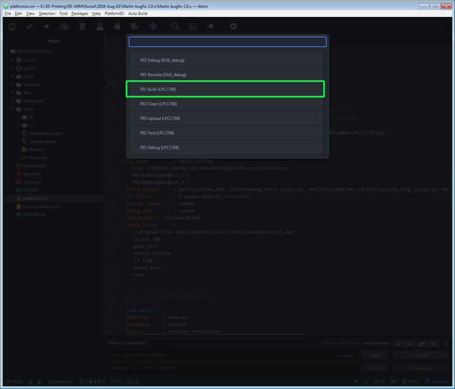
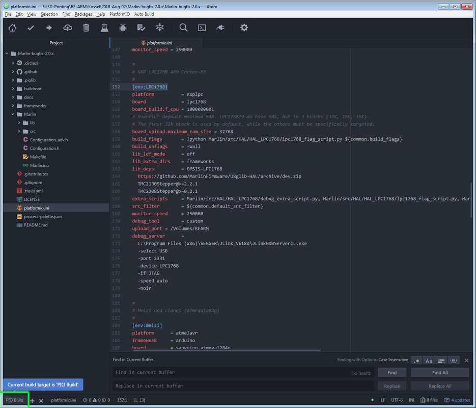
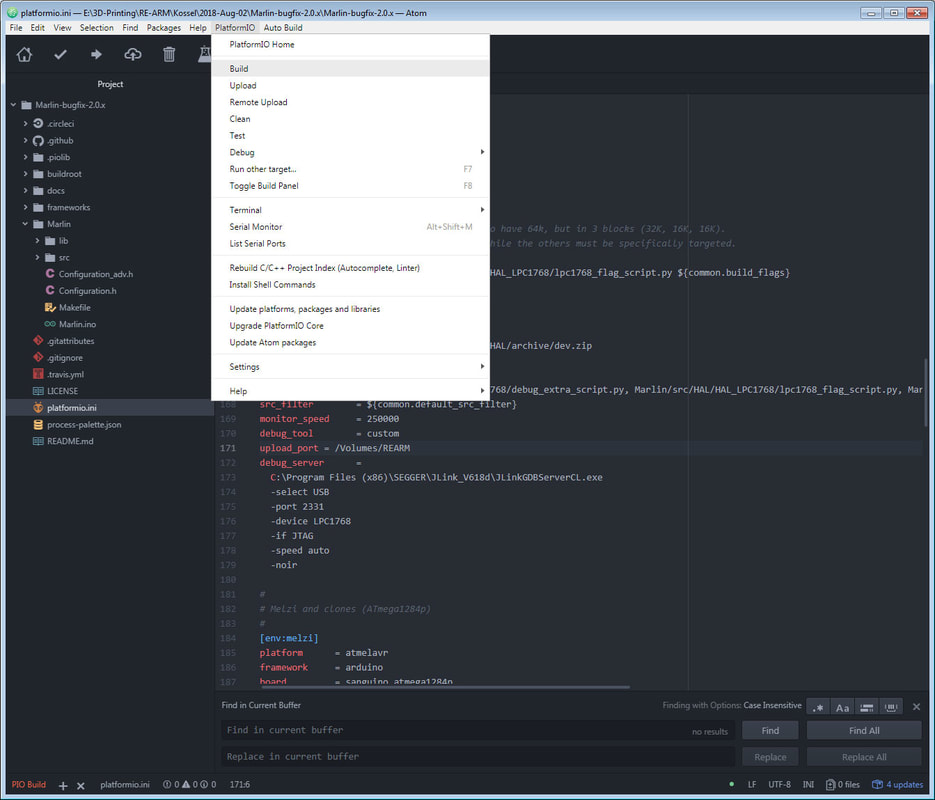
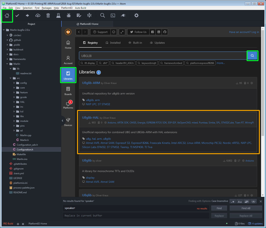
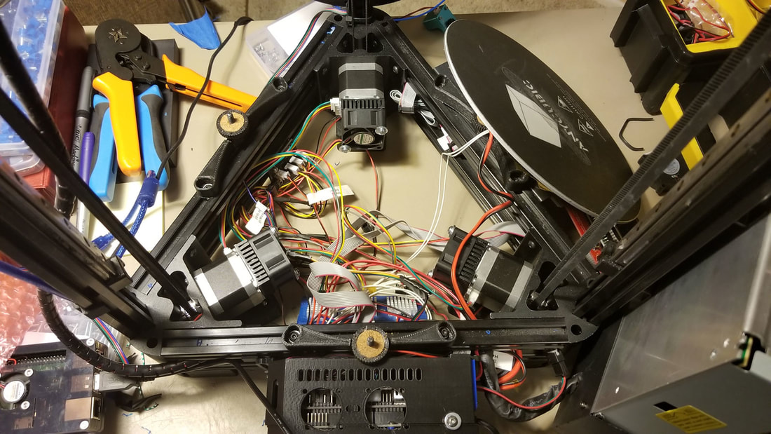
Installing Atom and Platform I/O Now that the limitations (as I know them) are out of the way, here is the basic process to getting Marlin 2.0 compiled for the Re-ARM. The first thing I needed to do was install Atom and Platform I/O, which I won't lie, was a pain in the butt. I used the following guide for that: http://marlinfw.org/docs/basics/install_platformio.html and this (which is linked in the above) http://docs.platformio.org/en/latest/ide/atom.html#installation I had problems installing CLANG so I skipped that, and have had no problems because of it. I did not take good notes on this process, so this is a bit light. In the above guide, I don't recall doing any of the "new project" stuff, I just opened the Marlin directory (see below). One thing to note is that when running Atom, it needs to be run as administrator (that is, right click the icon, then "Run as Administrator"). If that is not done there will be a bunch of errors. Opening the Marlin-bugfix-2.0.x file in Atom To start, I would close out Atom, and re-open it (run as administrator). Then close the welcome tabs that open up to clean up the workspace. Then I went to file > Open folder and navigated to the Marlin-bugfix-2.0.x directory. Once open, there will be a directory listing on the left side pane. Setting up Atom to compile So, this is jumping ahead, since nothing has been changed yet, but to confirm that Atom will compile with just a base Marlin config out of the box, a test run should be made. How to compile is not obvious with Atom, and since it does not know what we are compiling for (that is, it does not know if it is compiling for an Arduino Mega, a Re-ARM or a Ford Model T), we have to tell it what board we are using. To do that, there are 2 ways I am aware of. First, we can tell it when we compile - but that needs to be done each time. The simpler way to go is just to follow the guide linked above - specifically we need to edit the platformio.ini file. To do that, just double click on platformio.ini (which is under the "Marlin" directory), from within the Atom editor and it will open as a tab: Now just change the following: env_default = LPC1768 and then add this in the section under "[env:LPC1768]" (does not matter where): upload_port = /Volumes/REARM The effect of this will be to allow you to just compile and each time without selecting the specific type of board, and Atom will know what you are compiling for. Note however that this is all contained in the platformio.ini file which is inside the specific Marlin-bugfix-2.0.x directory that is being worked on. If you change that, then the changes to platformio.ini will also need to be done over again. If you continue to work from the same directory though then it should not change. The alternative method of compiling, without modifying the platformio.ini file, is to select the board each time when compiling (don't compile just yet though since the configuration.h needs to be updated for the Re-ARM). Re-ARM specific configs for configuration.h At this point, I would save, and then close atom out, and re-open it (run as administrator). It seems like after installing libraries or making changes to the platformio.ini and such it helps to do that. Then open up the configuration.h to make the following changes (I would run at least one test with just the base configs before modifying the config files for everything): For the Re-ARM the necessary configs in configuration.h are (these need to be changed) - see this link for more info: #define MOTHERBOARD BOARD_RAMPS_14_RE_ARM_EFB #define SERIAL_PORT -1 Once everything else is set up, you can save it (file > save) and compile it (read below for info on how to do that). I also found that I had to disable the speaker by commenting out the following in configuration.h, due to an error when compiling: //#define SPEAKER I think that error has to do with this. If you get an error, try that. Compiling the firmware.bin using Atom To compile, you can either click the "PIO Build" text-like button on the bottom left of the screen, or use the platformio>build menu at the top: I would just try compiling Marlin with the default settings to make sure it does not derp out with errors as a test (so you know it works when it derps later on). If it does work, it will just zip through a bunch of stuff in a pane on the bottom right of the window, and close then pane showing the progress (at the bottom left the " PIO Build " text will be green). If it fails the pane with the errors will stay open and you can try and see what went wrong. If it fails, the "PIO Build" text at the bottom left will also be red instead of green. If it was successful, Atom will create the "firmware.bin" in a sub directory, sneakily hidden several folders inside the Marlin directory: Marlin-bugfix-2.0.x\Marlin-bugfix-2.0.x\.pioenvs\LPC1768\firmware.bin That is going to be the file to load onto the 32 GB microSD card (which should be formatted as FAT32 and named "REARM") - when things are ready to go. I always check the date, timestamp and size to be sure it looks correct so I don't load up some older firmware by accident. Once I had a good firmware.bin with just the base config for the Re-ARM, I loaded it onto the Re-ARM to test, and then was able to connect to it and send it gcodes from Octoprint which confirmed it was working. If it failed with just the basic config, which seems unlikely, it may be missing a library, the errors should indicate that. If it worked then the configuration.h and configuration_adv.h can be edited to work with the specific config needed and then compiled and loaded onto the Re-ARM. If something does not work with the specific configs, it may be because it cannot work - at least in same way as before. An example is TMC2208 drivers using the serial control. For the TMC2208, I was only able to compile it using them in "standalone mode" since the pins needed to allow serial communications with the Re-ARM are not defined in the pins_RAMPS_RE_ARM.h file. I don't think that is an oversight or error, but probably due to the missing I/O's on the Re-ARM vs the Arduino Mega. The TMC2208 would probably work with serial control if I figured out which pins to use and edited the pins file, but after looking it over I decided that it would be a mess of wires here and there. The TMC2130 which uses SPI however, did compile in both standalone mode and with SPI control. In both cases though, the libraries would need to be installed for the driver being used. If using the A4988 drivers, no libraries are needed. ATOM Libraries (may be needed depending on the drivers used) I am a bit fuzzy on this point, but I recall that I had some compiling problems initially, so I had to install some libraries within Atom. Aside from the TMC drivers, my suggestion is to just compile, and if it has a problem, see if it says it is missing a librany, then install it and re-try. To install a library, click the home icon, then on the vertical pane, click the library, and search, and then install. The following are the libraries that I recall I may have needed at various points: U8glib-HAL by Oliver Kraus I can't recall if I needed this one or not, but I see it was installed. There are several of these, but the one I have installed is the U8glib-HAL. TMC2130Stepper by teemuatlut - used when I was checking to see if I could compile Marlin 2.0 for Re-ARM using the TMC2130 stepsticks. If using TMC2208 drivers (which I could only compile as "standalone" mode stepsticks), the TMC2208Stepper by teemuatlut would be needed. After installing a library, I would close and restart Atom (running it as administrator). Once you have a good firmware.bin (check the date, time and size on the file to make sure it is correct so you don't load an older or invalid one). Follow this guide to install it (basically load it up on the microSD which was prepared earlier and reset the Re-ARM): http://marlinfw.org/docs/basics/install_rearm.html Note that they state that the Re-ARM should be disconnected from the RAMPS board, and running off USB power (USB / Int jumper set to USB) the first time you test the config on it. If you do that, just be sure to move the jumper back to INT when done (and before you install the RAMPS), so the Re-ARM will run off the RAMPS power supply. It is not possible to move the jumper once the RAMPS is installed. If the RAMPs being used will have non-standard pins or anything that could send a signal > 3.3V < 5V to the RAMPS, double check that the pin it will send it to on the Re-ARM is 5V tolerant. If using mechanical endstops and a basic config, there should be nothing to worry about. UPDATE Nov 17, 2018 - Please see the comments. Since I wrote this in August 2018, there has been a change to the way Marlin 2.0 handles the SD card on the RepRap Discount Smart Display. Now, changes need to be made in the "pins_RAMPS_RE_ARM.h" to enable the SD on the display - but there is also now an option to use the MicroSD onboard the Re-ARM which may be preferable. Thanks to sl1pkn07 for pointing this out. I also cleaned up some spelling and added some links in the original post, but did not make any significant changes. In a nutshell, if you are using a newer version of Marlin 2.0 (since Oct 13th I think), and want to use the SD on the display, the Marlin-bugfix-2.0.x\Marlin-bugfix-2.0.x\Marlin\src\pins\pins_RAMPS_RE_ARM.h needs to be edited as noted in sl1pkn07's 2nd post in the comments - the following needs to be commented out in pins_RAMPS_RE_ARM.h, for the SD on the display to work: #define LPC_SD_LCD // Marlin uses the SD drive attached to the LCD //#define LPC_SD_ONBOARD // Marlin uses the SD drive on the control board I am pretty sure the same caveat regarding occasional garbage lines on the display will still apply, but the SD on the display should work as before. Of course if you want to use the MicroSD on the Re-ARM, that is now the default, so you shouldn't need to change anything in that case. Update May 25, 2019 - switching to VSCode + PlatformIO IDE: Alot has changed with Marlin since I made this post, and I think they have fixed or worked around the LCD and SD card issues (not 100% sure on that but I saw some things in the config files that would lead me to think that is the case). However I wanted to add a note that I am switching to VSCode since that seems to be recommended for PlatformIO now. VScode is to PlatformIO the same way Atom is to PlatformIO, they should be pretty much interchangeable. I had problems with Atom when I went to rebuild Marlin recently so it was a good time for a change anyway. I put together some things that helped me get VSCode working here. I am not up and running with code created with VSCode + PlatformIO yet however, but I think it is at least working to compile Marlin. 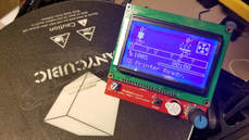 Between my Kossel not working reliably and my Ender 3 doing an impression of a rock, I was at a crossroads. The Ender3 has intermittent and frustrating extruder problems, so I want to get rid of the boden setup and swap it with a direct drive Titan Aero clone), but that requires a new mount. My Kossel has been acting weird for months with layer shifts, so I could not use it to make the parts for the Ender 3. Yep, both my printers suck. Hopefully that will start to change though since today I did a motherboard transplant on my Kossel. It now rocks a 32 bit Re-ARM and RAMPS 1.5 board, with Marlin 2.0 providing the magic sauce, and best of all it works (though not without the now expected pain and suffering). Aside from almost cutting my pinky off, I bought some stepper extensions that I did not check closely. Normally I would not consider stepper extensions to be a problem, since how can somebody screw up 4 wires and 2 connectors (he, he), but mine were mis-connected. The result was steppers that did the boggie but not much else. I also had a problem with the display not working (lit but would not show anything). I just had the wrong display defined in the Marlin configuration.h: Had this: #define REPRAP_DISCOUNT_SMART_CONTROLLER should have had this: #define REPRAP_DISCOUNT_FULL_GRAPHIC_SMART_CONTROLLER Got that fixed and it works great. What is most important to me though, is that I got all axis working, endstops are endstopping and themistors are thermisting - and the heaters work too, so all the important systems are go. Since I did not want to have this mess of wires are electronics flapping in the breeze I was able to salvage several failed prints to make a sort-a enclosure for it all. The fans are all tired into PSU now since previously I was too lazy to take apart the PSU to connect them in. Once I get this calibrated, printing an enclosure will be at the top of the agenda, well after several other projects that have been piling up. This is running Marlin 2.0 and I am just using the original drivers (A4988) which I've connected to TL-Smoothers. Now that I know it works I am going to order some TMC2130 drivers since they should work with the Re-ARM (which is pin limited compared to the Arduion Mega). |
Stoopid MeWelcome to my Stoopid corner of teh Internet. It's mostly gonna be 3D printing stuff, but I also post some recipes, projects, and the occasional rant here as well. More Stoopid stuff is updated regularly. Archives
July 2024
Categories |



 RSS Feed
