My Stoopid Stuff
  • Home
  • Projects
  • Blog
  • Lec'tronics
  • Links
  • CNC
  • Quick Recipes
  • 3D Printer Tips

Retraction and Coasting, one pulls the other one pushes

9/26/2021

0 Comments

 
Picture
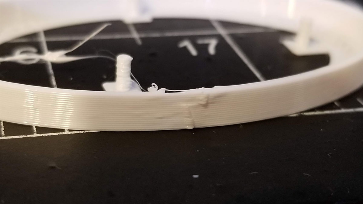
I have been seeing blobs on my prints and have tried a few things to fix them, because it is getting to be a problem when running PETG especially.  I know that the blobs are due to the nexus of retraction, speed, flow, temperature and coasting volume, and maybe something else I have not considered.  That's a lot of knobs to adjust though, but I'm trying. 

The material I am using is Duramic3D White PETG, which is generally my go when I need PETG.  I ran some temp towers and found that the best temps are between 230°C and 235°C so I am going with the lower value.  I calibrated flow using single wall cubes, where normally I run a 2 wall cube, but the value was quite a bit lower than I expected at 89%, but it does work.  I also re-checked my e-steps which right on 140 steps per mm. 

So I am checking off some of the boxes but the blobs are still there.  I'm down to retraction and coasting, which seems to me are two ways to deal with a pile of filament that needs to be gotten rid of.  My understanding is that coasting pushes the pile along and spreads it out, and retraction sucks up whats left.  To get into the ballpark for the retraction setting, I ran several retraction tests first, which were not great, but I settled on 5.2mm @ 25mm/s yet still seeing blobs.  One limitation potentially with the hot end I am running however, is that (IRRC) Microswiss recommended staying below 4 or 5mm for retraction.  I have never had a problem going to 6mm though, so I'm not really concerned yet.

You can skip to the end if you just want to read my go-forward plan to deal with ugly seam blobs on the surface of prints.

Finally (maybe), I'm looking at the coasting volume.  For some reason, even though I have a 0.6mm nozzle, Cura wants to default to the value for a 0.4mm nozzle (0.064mm^3).  The coasting volume should be close to the diameter of the nozzle cubed, so 0.4mm nozzle would be 0.4x0.4x0.4 = 0.064mm^3 and a 0.6mm nozzle (which I am running) should be 0.6x0.6x0.6 = 0.216mm^3.  So I first ran a baseline test (TEST 1) using a model I created after Brilliant Name's "Underextrusion, retraction, extra prime and coasting test" (https://www.thingiverse.com/thing:3229413/).  That model is designed for a 0.4mm nozzle so I had to make mine for a 0.6mm nozzle, and I also added a 2 layer brim.
Picture
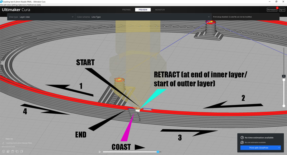
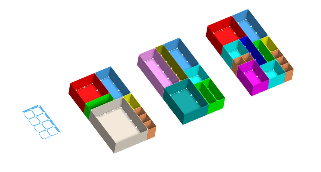
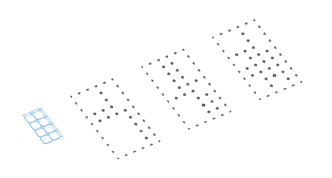
UPDATE 9/27/2021 - I went back and re-worked the image above since I made a wrong assumption previously about it.  Above is how I understand it after loading the gcode back into Cura and replaying it, though one thing I am not certain of is if the "starts" which are represented by white dots or boxes on the print when displayed in Cura - are where a retraction will occur or not.  The best I can come up with currently based on the way the test model prints is that the inside layer is done first, so there is a "start" (and maybe a retraction), and then nozzle moves clockwise around the inner loop from 1 to 2, then it coasts a bit at the end of the inside loop.  Now the nozzle makes a u-turn into the outside layer.  I think that a retraction occurs at this point at the start of the outside layer (where the white area is on the pic).  This is also where I see the blobs typically on my prints.  Next, the nozzle starts the outside layer in the counter clockwise direction from 3 to 4 and then when it gets to the end, it coasts again for a bit, and finally moves back over the inside layer to print one of the posts, I don't think it makes a further retraction on the outside layer since the next one appears to occur where it starts one of the small posts off to the left (not shown).  So if I am interpreting this correctly, that would indicate that the blobs I am seeing in the tests below, are due more to the retraction done as the nozzle moves from the inside layer to start the outer layer (after coasting to the end of the inside layer).  This makes sense based on my test results below which show coasting had less effect that retraction did. 
One thing I noted going into this was that the default coasting volume had been set wrong for my 0.6mm nozzle (set for 0.064mm^3 which corresponds to a 0.4mm nozzle). Still I tested with that coasting 0.4mm nozzle value to start with and then tried the recommended coasting value for my 0.6mm nozzle.

Coasting Volume and retraction Tests (run via Octoprint).

Using these values (to start):
Speed 40mm/s
Accel 500mm/s
Jerk  7, 7, 7
Flow  89% (Duramic White PETG)
Temp 230°C/60°C
Layers 0.2mm
Retraction 5.2mm @ 25mm/s (this was changed after test #3)


Picture
Picture
Picture
Picture

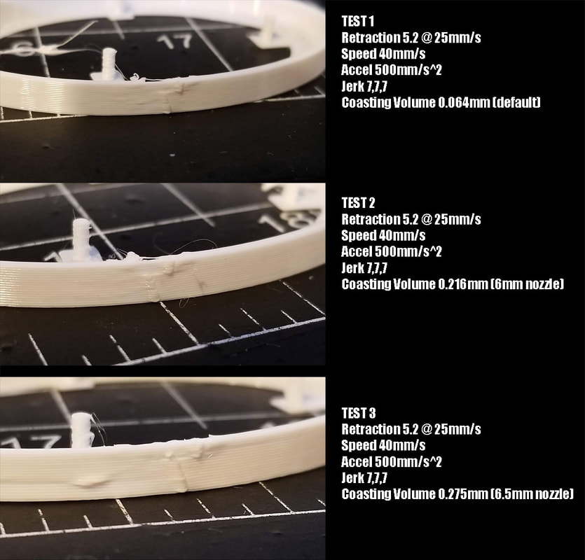
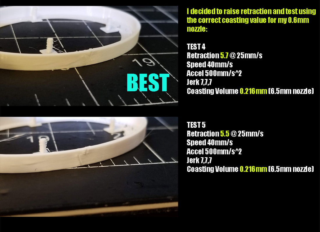
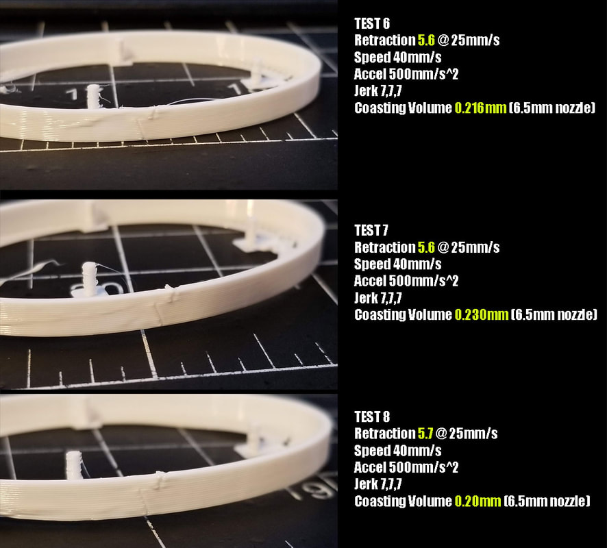
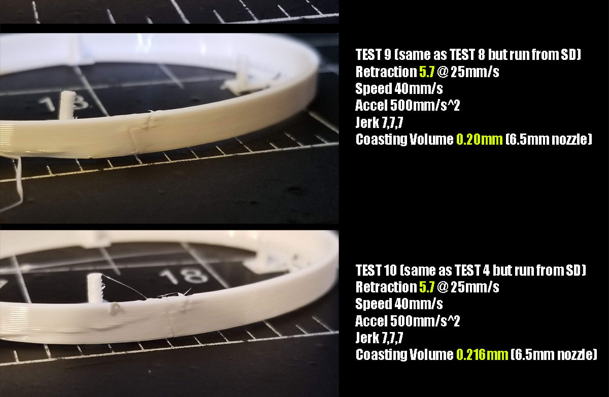
The first 3 tests where to see if changing the coasting volume helped (these alone did not help much - read below):

TEST 1     coasting volume 0.064mm^3 (incorrectly set for a 0.4mm nozzle)
       Result - not a big difference, still ugly blobs

TEST 2     coasting volume 0.216mm^3 (0.6mm nozzle)
       Result - not a big difference, still ugly blobs

TEST 3     coasting volume 0.275mm^3 (0.65mm nozzle) - ugly
       Result - not a big difference, still ugly blobs

The results so far are not great and there is not much difference between them.  I decided to take a different tact and, although I calibrated the retraction previously, thought I should have another look at it.  For every 0.1mm in retraction, on my 0.6mm nozzle, I should see the same effect as 0.028mm^3 in coasting volume.  So, an additional 0.5mm of retraction should yield a similar effect to a adding 0.141mm^3 in coating value, and that should be noticeable.

TEST 4     coasting volume 0.216 (0.6mm nozzle) [BEST]
      retraction increased from 5.2mm to 5.7mm @ 25mm/s
       Result - better now a bit too much retraction

TEST 5     coasting volume 0.216 (0.6mm nozzle)
      retraction decreased to 5.5mm @ 25mm/s
       Result - needs a bit more retraction, the bulge is back

TEST 6  coasting volume 0.216 (0.6mm nozzle)
      retraction increased 5.6mm @ 25mm/s
       Result - not a big difference, still a bit of bulge

TEST 7  coasting volume increased by 0.014 to 0.230mm^3 (0.6mm nozzle)
      retraction 5.6mm @ 25mm/s
       Result - not a big difference, still a bit of bulge

Decided here to backtrack from TEST 4, and try less coasting volume and the same retraction as in TEST 4:

TEST 8  coasting volume decreased to 0.2 (0.6mm nozzle)
      retraction increased 5.7mm @ 25mm/s
    Result - Still a bit blobby, and I feel it is worse than TEST 4, so I think TEST4 is the winner.

These last tests are running the same test as TEST 8 and TEST 4, but instead of running from the Octopi, I printed it from the SD card.

TEST 9
  coasting volume 0.2 (0.6mm nozzle) [same as TEST 8, but run from SD card]
      retraction 5.7mm @ 25mm/s
    Result - No real changes from TEST 9

TEST 10 coasting volume 0.216 (0.6mm nozzle) [same as TEST 4 (best), but run from SD card]
      retraction 5.7mm @ 25mm/s
    Result - Possibly some improvement from TEST 4 (its hard to tell)
In a nutshell, it looks like retraction is better for cleaning up blobs but maybe coasting can be used to polish things up a bit.  It's not a big surprise really, but I have not tried calibrating coasting, and I now see that it has been incorrect (way too low) for much of the time I have been using a 0.6mm nozzle, so I'm happy to have that fixed.  I also think that the way I was testing retraction using the tower type stringing tests may not be the most optimal for surface finish, since the tower type stinging tests are looking at what is really the toughest case, but surface finish is something that is a more general concern with most prints.  Maybe need a balance between stringing and surface blobs, but I will lean towards trying to reduce surface blobs and take care of stringing the old fashioned way.  Finally, I could probably do another 10 tests and tweak this some more, and may do so, but for now I'm gonna see how an actual print looks with the new settings.

Here's what I'm gonna do in the future when I run into blobs on the surface related to coasting and retraction:

So in a nutshell, what I plan to do in the future when I really need to clean up a print, is to:

1.  Calibrate flow (using a single or double wall test cube)
2.  Calibrate temp (either using my notes or a temp tower)
3.  Use this thing (for 0.4mm nozzles) or this thing (for 0.6mm nozzles), to calibrate the retraction first, using the recommended value for coasting based on the nozzle size (which is the nozzle diameter cubed).  I will however need to be in the ballpark for retraction to start, which should be easy since I keep track of these settings in a spreadsheet.
4. Once retraction is as good as I can get it, I will adjust the coasting up or down by 0.014mm^3 (on a 0.6mm nozzle) which (I believe) is a similar amount of ooze that could be adjusted by changing the retraction by 0.05mm.  On a 0.4mm nozzle I would try going up or down by 0.003mm^3 once retraction was as good as I could get it. 

It should also be noted that this retraction test seems best for cleaning up surface blobs vs stringing, which may be an either/or balance of even more retraction to clean up stringing or dealing with some stringing but having a better surface finish.  I don't see enough of a change between using Octoprint and the SD card, so I will stick with Octoprint for now.


0 Comments

Drawer Organizer for an IKEA Alex (Canceled see last note)

9/24/2021

0 Comments

 
Picture
I looked around at drawer organizers for the IKEA Alex and saw some that were really good, but missing one feature - some way to keep the bins from moving around if one was removed.  Some systems use a grid to get around this but that means a more complicated print.  I also don't need the compartments to be held in too tightly since there is not going to be any lid to keep them secure anyway, I just want to keep them in position.  I'm gonna try to use some pyramid shaped "keys" to help keep things aligned, and they will be placed with a guide so things can hopefully stay consistent.  The keys will be held in place using clear VHB tape and they are sized 12.8mm square, so a 1/2" wide VHB tape should work.  This system has one major drawback, being that once the design of the drawer is set up, it will be hard to change, since the grid is only where it needs to be.  The keys could be removed and moved, but with VHB tape will be hard to remove.  Additionally these will be long prints.  The largest box is more than 8 hours, but since they are simple, I should be able to increase the print speed.  Although with a 0.6mm nozzle they only have 2 walls, the smallest box still takes about 2 hours on my printer.  I did test with "spiralize" (or vase mode), which prints with just one wall, and though it prints quickly, it is not strong enough and missing the corner tab details.  I have no idea when this may be posted, but I wont be posting it until it's tested, and that again is gonna take some time to fit out a drawer with these.
Picture
Picture
Update 9/30/2021: I decided to cancel this project after printing several of the boxes.  I feel that it could work, but I've come around to the idea of using the grids to index the bins, as long as I can print the larger ones without supports, which I don't think will be any issue.  I'm currently working on a design similar to this, but the bins are larger for the Ikea Alex drawers, and I made the bins a bit thicker since my printer is using a 0.6mm nozzle.  The design I'm working on is not a direct remix, but I am definitely taking design queues from Duke Dok's design.
0 Comments

Something Seems Not Right Here ...

9/21/2021

0 Comments

 
Picture
Oh well, it was at least useful to know that everything else fits.  Also probably time for a new PEI sheet, it's starting to look pretty bad.  Will flip the port for the Keystone around and try again.  For reference pics, see the 2nd post down for this display housing.
0 Comments

JKTech's Smart 3D Printer Enclosure Electronics V2

9/19/2021

2 Comments

 
Over a year ago I bought an Enclosure Monitor System board from JKTech, and because I wasn't sure where or how I was gonna wire things up in my enclosure (still working out the details), and then I lost the kit, it never got checked out.  However I found it recently, and am making an effort to get things wired up in the enclosure now, so I thought I would share some pics and initial thoughts of his product.

The kit ships with the board only, which has the 5V buck converter installed and configured.  It takes 12v in, and everything is well labeled.  The Arduino, 3.5" Nextion touchscreen, and temp/humidity sensors are all purchased separately.  What I got was a very well designed and assembled board, and the code to run on the Arduino and the touchscreen software as well, which is a good deal in my opinion.  I have no affiliation with JKTech, but it is currently on sale for €35 or about $41 plus reasonable shipping.

Picture
My first thought after setting it up was that that this board is very cool and is pretty much all I need for controlling the enclosure.  Once the Arduino was programmed, everything was plug and play and just works (I have not tested fan PWM control yet).  The LED control is very cool, and there are a number of preset modes (rainbow, heartbeat, solid and a color based on the temp sensors).  There are also two temperature and humidity sensors supported (I only have one connected right now), and there are other cool monitoring features designed into the programming which I have not checked out yet.  The board has a small (2A I believe) adjustable buck converter, which is set to 5V and makes for a very simple no solder set up. 

By default, due to the current limitations of the onboard 5v supply (which can be bypassed), there are limitations on the number of 5v LED's that can be safely run without over driving the 5v converter.  The number of LED's is also dependent on the current drawn by fans controlled by the board as well, since everything connected to the 5v converter needs to stay under the current limit for the buck converter.  I don't recall the exact number of LEDs that can be used, but I feel it's enough.  What you see in the pics is, I think the default number of LED's (if more are needed, they can be added by editing one line in the arduino code which is very simple).

When I initially set the board and display up, I found that I had to shorten the length of the cable between them to a couple inches or there would be problems with the serial communication between them (the trimmed down stock wire harness can be seen in the above pic, which was connected to a Cat5E cable for testing).  However I discussed with JKTech and was advised that the latest firmware has some changes to help with this, and now there should be no need to shorten the stock cable that ships with the display (which again is bought separately from the controller board).  I don't recall which version of the code that I used, so will need to check that I got the latest installed.

I'm going to extend the display away from the controller by 1.5 to 2 meters however, so I tested with about 1 meter of stranded twisted pair Cat5E cable to extend the display, and I found it works perfectly.  I'm sure it will be fine with longer lengths since serial communication can go I think 30 feet at least with a proper cable (I think).  Edit 9/22/2021 - I tested with a 4m cable and it also worked fine.  I may try paralleling some of the extra wires in the cat5e cable to help with power, so it looks very promising (Edit 9/22/2021 - this was not necessary for my setup, it works fine with just one pair for power).
Picture
Picture
I've also remixed an enclosure for the Nextion 3.5" Touchscreen display ( model NX4832T035 ) from HeinAndre's Nextion Desktop Dashboard Case, so I can keep it remote on top of the enclosure unless I find a better way to mount it.  It has a keystone jack and I plan to use a standard patch cable to connect it (noting that this is not running Ethernet).  I will have to do some careful wiring on both sides of the jack and make sure to label it so it's clear it is not Ethernet.
Picture
Update 9/20/2021 - I decided to add a power switch to shut down the display since I may not want it on all the time.  I also made some changes for better printability.  I'm going to print it this week and test it out.
Picture
Update 9/21/2021 - The enclosure is finished and I put it together today (after a brief detour with backwards facing Keystone jacks).  At least I didn't waste to much PETG prototyping this one.  And the good news is that the screen is working perfectly in the enclosure.  I even got it to work without any changes to the software using a 12' CAT5E cable (longest I had right now).  I noted that the power switch will not work the way I connected it, since although it does kill the power to the screen, the screen will not automatically re-synch with the Arduino until the Arduino is reset as well.  No big deal though since I'm gonna use it instead to control an optoisolated relay board that will power on and off the V2 Electronics board.  I added a version of the backshell without the switch knockout, as another option to use.

The Nextion 3.5" Screen enclosure is posted here:

https://www.thingiverse.com/thing:4970457

2 Comments

I'm Gonna Try Out Amazon Affiliate Links (again)

9/18/2021

0 Comments

 
Several years ago I tried out Amazon Affiliates Links and made exactly zero dollars at it, so I removed them and stopped bothering with it.  I have since built up some content, and thought that it may be worth trying it again, so I recently signed back up and will see how it goes.  I added a note to the sidebar to the effect of “As an Amazon Associate I earn from qualifying purchases.” and will add that in other places since it's not like I'm trying to hide that fact.  I'm more curious how it will work, and if I can re-coup some of the money I spend on filament and parts for prototyping the designs I make, that would be super.  If you don't want to use the Amazon affiliate links, I will try and describe the product so you can also just search for it if you prefer, but if you do use them, thanks for supporting this site (which is really just me and my Stoopid hobbies :D).
0 Comments

Quick Label Dispenser (Completed)

9/17/2021

0 Comments

 
Picture
My Dad asked for a label dispenser for a roll of labels that is 60mm in diameter with a 25mm hole for the tube and approx 55mm wide (similar to these), so I remixed one I found on thingiverse here (https://www.thingiverse.com/thing:2361685).  The main changes are a knob that screws on to secure the lid, and some indexing tabs on the inside of the lid to help keep it in place.  I have to print this and if it works I will post it up to Thingiverse and Cults3D.

I plan to mount this using large 3M command strips, however it also has 4 holes for mounting using flat head screws.
Picture
Just a few updates, printing this now to test that everything works.  It will now mount to the wall and has fewer parts.
Picture
Update 9/18/2021:  Its done and is now posted on Thingiverse:

https://www.thingiverse.com/thing:4969670

The link is updated 9/20/2021 since I had to remove and re-add this due to a bug on thingiverse which keeps some things from being searchable or showing up in "my designs".

Picture
Some of the links posted here are affiliate links which help me earn a small commission and supports this site.
0 Comments

Repaired the Battery for my Dad's Pool Blaster with a BiRF 9 "Gears" Battery Spot Welder

9/4/2021

0 Comments

 
Picture
My Dad is on his 2nd Pool Blaster in about 4 years or so, and when they work, they work great, but both have had problems out of warranty.  Now his 2nd Pool Blaster is dead.  We had swapped a non OEM battery into the first Pool Blaster he had, before it finally met the garbage man a while later.  When the 2nd Pool Blaster failed after more than a year, I took the 2x(Series)18650 battery pack apart, and found one of the cells had died, and would not charge in my Opus BT-3100 charger, but the 2nd (good) cell in the pack will charge.  The Battery Management Board (BMS) on the factory pack has a tab connected between the cells, so it should be able to balance them, so I dunno why the cell died (the cell that died was the first cell in the pack, connected to the positive terminal).  Instead of trying to swap the pack this time, I decided to get a battery spot welder and try to replace the cells with better ones. 

To do that, I bought the "BiFRC 9 Gears Mini Portable Battery Spot Welder" for about $40, and some Molicel P26A 35A 2600mAh 18650 cells along with some 0.1mm x 5mm nickel battery strips and paper insulator rings for the ends of the cells.  The total cost for everything was about $50 not including shipping.  I also ordered some PTC Polyfuses since the one on the pack was not re-usable.  When he needed it working again, I didn't have the polyfuse yet, so I just used a 5A automotive fuse so it could be used and when I get the fuses I will swap it in.

As you can see by the pics, I'm clearly no expert in making battery packs, but it was still relatively easy.  I think if I do this again I will make some printed battery holding jigs for making packs since getting them oriented was the hardest part.  Additionally I should have flipped the board over from it's factory configuration since it would have been easier to work with.

I may put the battery in an clipping from an old MTB tire with some zip ties to give it some water resistance but according to my Dad, the battery compartment is well sealed.  One thing to note about this is that they originally spot welded the connections to the BMS board, which I decided was probably not a great idea so I soldered them on the board once they were already spot welded to the batteries.  I know the welder should only affect the metal between the probes but I don't know if using it on a pad connected to active components could damage them (and I don't care to find out).  Soldering also worked just fine. 

The BiFRC Spot Welder worked great and I did not need to use a high setting to get welds I would consider to be as strong as the factory ones.  I used the old dead cell to test with and found that I could use the 2nd or 3rd "gears" for most of the welds.  I know that there are some videos where folks go much higher but I could not pull the welds off by hand without twisting the tabs and rolling them off with a long nose pliers, so I figured they were strong enough.  I uses dome polyimide tape to help hold the nickel strips in place while I was welding and got a bit of a spark from it when I got too close, but other than that it was pretty uneventful.  One nice "feature" of the welder is that it gives a tone when it senses that the probes are positioned to weld and then there is about a second before it welds.  That's handy since it allows for some quick readjustment before the weld zaps it. 

It may be tempting to just solder the batteries to make a pack, and when I was younger and battery spot welders were quite expensive, I made a few packs for my bike lights that way.   But soldering a lithium pack is risky for a number of reasons, including possible damage to the cell protection or a shorted cell.  Shorting a cell on an 18650 is nothing to take lightly either, I once had a small bead of solder roll off the positive terminal of an 18650 and weld itself between the positive terminal and the case (negative).  I was working inside the house at the time, and had just enough time to run out the door, and chuck it in the yard before the thing popped like a firecracker.  That experience gave me some more respect for lithium batteries and I pretty much stuck with NiMh from that point, when I had to build a pack.  But now that a battery spot welder is under $100 and even under $50 I think it would not make sense to take the risk with soldering packs unless they were designed for that.  I also recommend a protective face shield, or safety glasses at a minimum when working with the batteries.

I did however solder the tabs to the board after they had been spot welded to the batteries, and to minimize the heat, I first tinned the tabs and the pads on the board and let both cool down.  Then I got some solder on the iron and soldered the pads to the tabs as quickly as possible.  It's a good idea to have things arranged when soldering so that the parts will naturally sit where you want them to go, since you can't stick anything down with solder, if it won't sit right before soldering then it probably won't turn out well.  In this case, since I was working outside to take advantage of mosquito season, I had to rig up some things I had on hand to situate the parts so the pads and strips would line up prior to soldering. 

The batteries were also discharged in the Opus prior to being welded, just in case there was a short or some other issue they would at least have less juice.  Discharging them however has the effect of causing the BMS to shut them off once everything is connected, so the pack has to be charged up again to get it to "work".  That also means if the pack is checked with a volt meter, and the batteries are discharged, it will only register some mV, and appear dead.  I checked the charging current and it was charging at about 1.2A (fully empty).  Once charged I gave it a quick test and it worked but the true test will be when my Dad uses it in his pool.  I didn't grab pics of the battery after the board was installed but it is just mounted component side down facing the battery (which was how it was configured originally).


Disclosure: Some of the links here are Amazon affiliate links. This means that, at zero cost to you, I will earn an affiliate commission if you click through the link and finalize a purchase.
0 Comments

Installed an Ikea Drawer in my Enclosure

9/3/2021

0 Comments

 
Picture
Yeah it's a mess in the laundry room right now, but the printer will at least have a place now to hide the tools which usually end up on top of the enclosure.  This is an Ikea UTRUSTA drawer front (medium 302.656.35) and a MAXIMERA drawer (medium 602.656.72) which I installed using some custom brackets for the enclosure.  The drawer is just a bit narrower than the enclosure so there are some spacers which fill the gap, and are part of the brackets for the slides.  The Ikea drawers are a nice design with a soft close hinge and these have good quality sliders (not all of them do). 

I designed but have not yet printed a part which will hold a shelf separator under the drawer, which lights can be installed on.  Right now I'm trying to decide if the lower part of the enclosure should have filament storage (hopefully more organized than the current mess), or if I should try and cram my Ender3 in there and make it a full enclosure with ventilation and all the bells and whistles.

Right now I'm not planning to post the design for the brackets or the enclosure since this enclosure project as a whole is still a work in progress, and has been a big time and money drain (and would take more of each to get it ready to post).
0 Comments
    Picture

    Stoopid Me

    Welcome to my Stoopid corner of teh Internet.  It's mostly gonna be 3D printing stuff, but I also post some recipes, projects, and the occasional rant here as well.  More Stoopid stuff is updated regularly.

    I recently joined the Amazon Associate program, so some of the links on this site are Amazon affiliate links. This means that, at zero cost to you, I will earn an affiliate commission if you click through the link and finalize a purchase.  This will help to support this site, and pay for more Stoopid Stuff.

    Archives

    March 2023
    February 2023
    January 2023
    November 2022
    October 2022
    September 2022
    August 2022
    July 2022
    April 2022
    February 2022
    January 2022
    December 2021
    November 2021
    October 2021
    September 2021
    August 2021
    July 2021
    June 2021
    May 2021
    April 2021
    March 2021
    February 2021
    January 2021
    December 2020
    November 2020
    October 2020
    September 2020
    August 2020
    July 2020
    June 2020
    May 2020
    April 2020
    March 2020
    February 2020
    January 2020
    December 2019
    November 2019
    October 2019
    September 2019
    August 2019
    July 2019
    June 2019
    May 2019
    April 2019
    March 2019
    February 2019
    January 2019
    December 2018
    November 2018
    October 2018
    September 2018
    August 2018
    July 2018
    June 2018
    May 2018
    April 2018
    March 2018
    February 2018
    November 2017
    September 2017
    August 2017
    June 2017
    December 2016
    October 2016
    September 2016
    July 2016
    March 2016
    February 2016
    September 2015
    August 2015
    June 2015
    May 2015
    April 2015
    March 2015
    February 2015
    January 2015
    December 2014
    November 2014
    October 2014
    September 2014
    July 2014
    June 2014
    May 2014
    April 2014
    March 2014
    February 2014
    November 2013
    August 2013
    July 2013
    June 2013
    May 2013
    April 2013
    March 2013
    January 2013
    December 2012
    November 2012
    October 2012
    September 2012
    August 2012

    Categories

    All

    RSS Feed

      Contact Form (Name is optional)

    Submit
Powered by Create your own unique website with customizable templates.