My Stoopid Stuff
  • Home
  • Projects
  • Blog
  • Lec'tronics
  • Links
  • CNC
  • Quick Recipes
  • 3D Printer Tips
  • Voron 2.4

Testing a Thermistor Input on an Ender3 and CR10S Pro

7/31/2020

0 Comments

 
INFORMATIONAL ONLY - if you try this, it is at your own risk.

I do not recommend doing this, I only did this myself out of curiosity and to help a user on Thingiverse.com who had tested or swapped all the usual suspects but found his thermistor was never reading above 150C - which caused a thermal runaway situation which the firmware could not detect (very dangerous).  It's a really odd problem since the person had checked the resistance through the entire wiring on the thermistor down to the ribbon connector on the board side and it all checked out.  He was pretty much out of options and was about to plop down 80 bucks or so on a replacement board which may have been inevitable anyway.  I don't know what the result of his efforts was, but hope he got it sorted out.  In any case, I was trying to think of another way to test the input on the board itself, and thought of replacing the 100K Ohm thermistor with a 100K Ohm potentiometer, which after doing some searching is not a novel idea.  This would rule out any issue with the thermistor and I'd be able to control the voltage that the thermistor input detected directly using the potentiometer (for testing only).  I'm no expert on this stuff, but from my understanding, the ramps based boards out there just use a simple voltage divider, with a 4.7KOhm resistor on the upstream leg and the thermistor on the downstream leg going to an ADC input to the board.  I've used this setup in a couple of projects to control ADC inputs with a potientiometer or resistors, and don't know of another way to do it really.

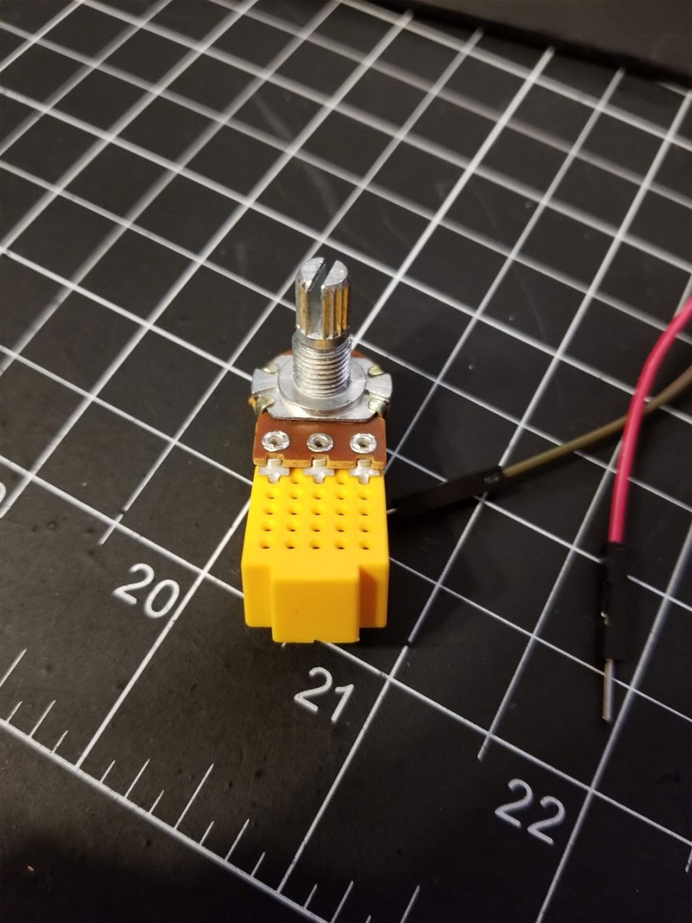
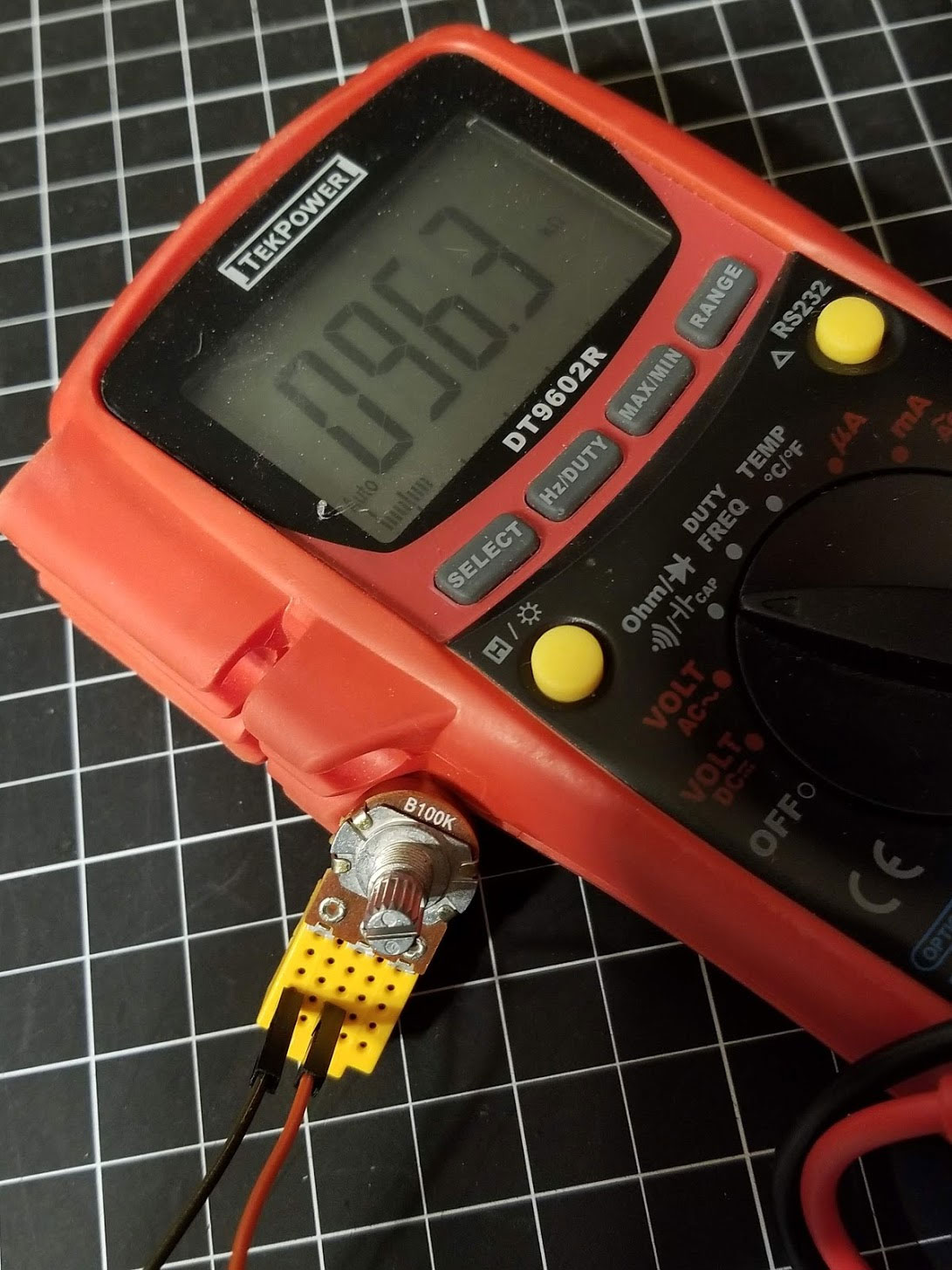
The test setup worked, but in practice it did not work well since I used a "linear taper" potentiometer, where the thermistor is not linear in it's rate of change to temp.  In other words it was sketchy when I adjusted the potentiometer above about 160C as the displayed temp.  I think an "audio taper" potentiometer would have been better for this.  Because my printers use a 100K NTC thermistor I tested with a 100K Ohm potentiometer.

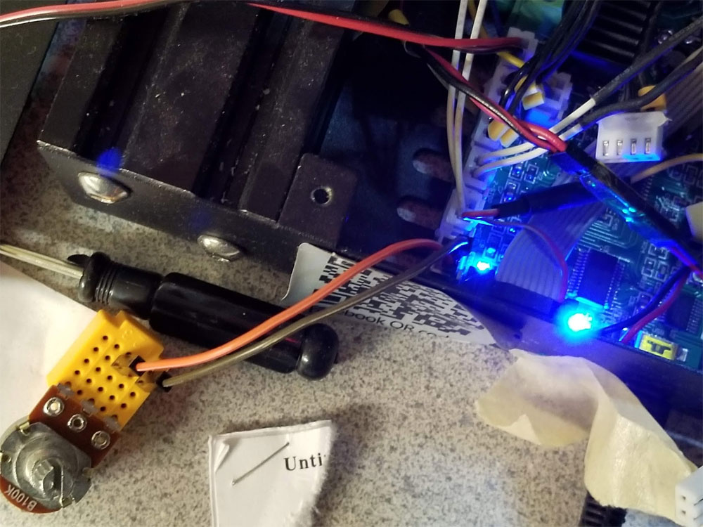
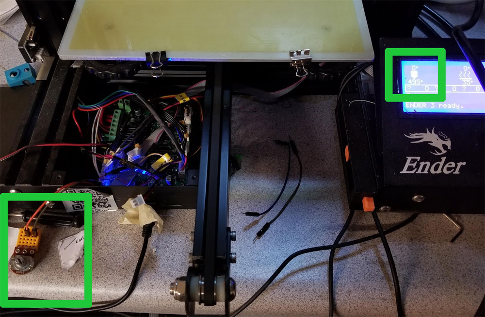
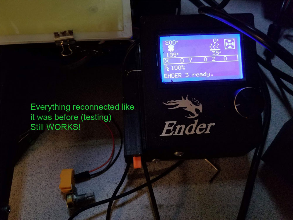
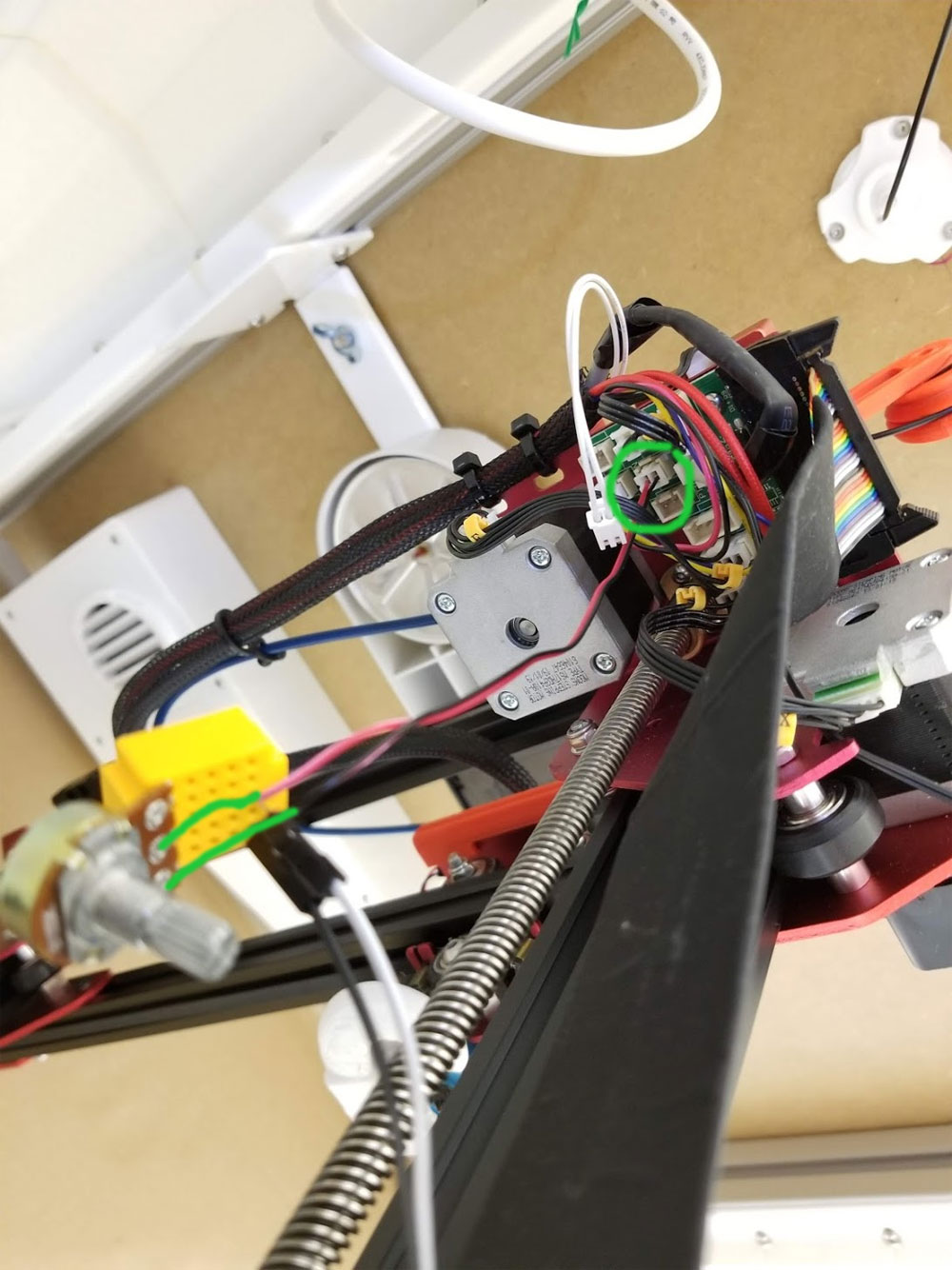
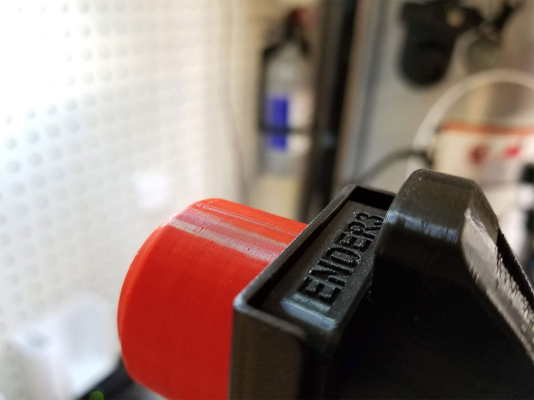
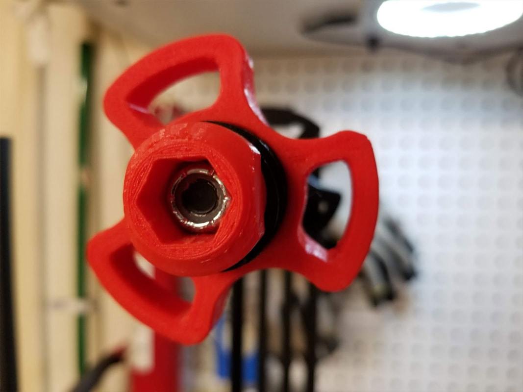
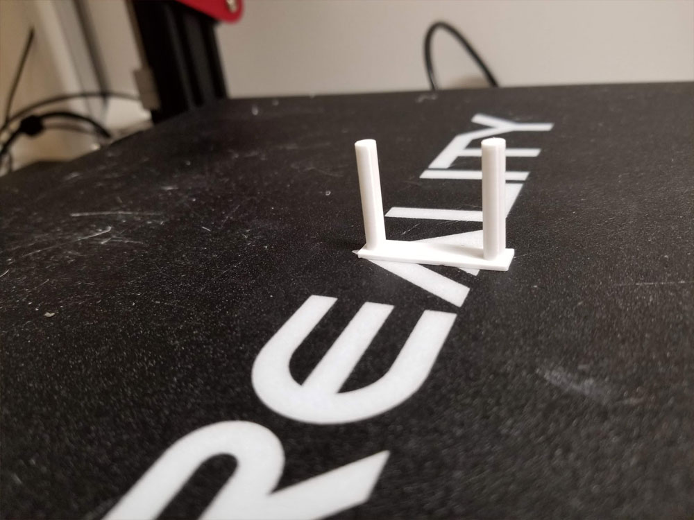
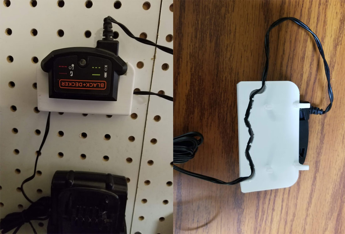
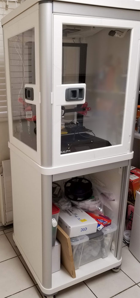
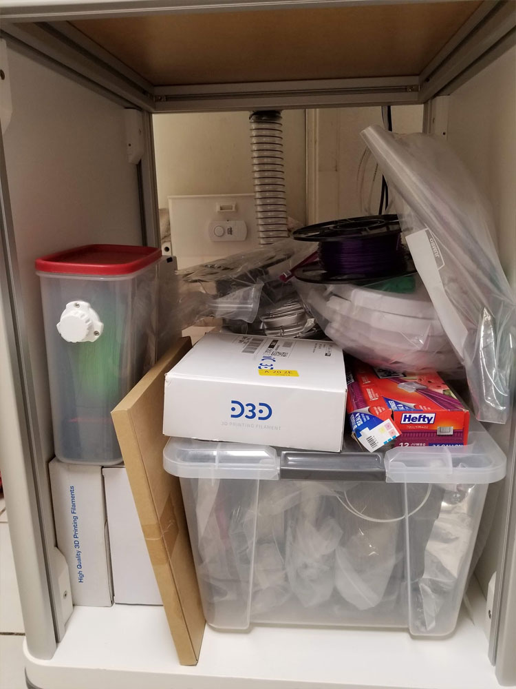
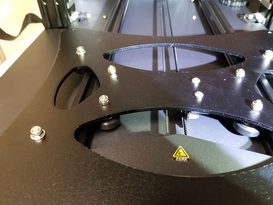
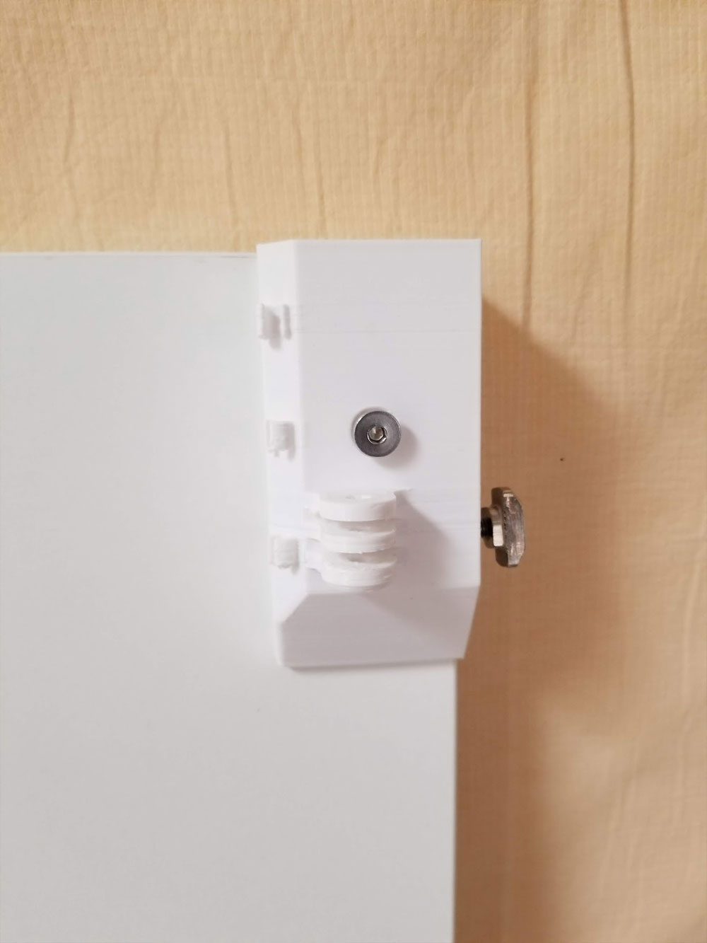
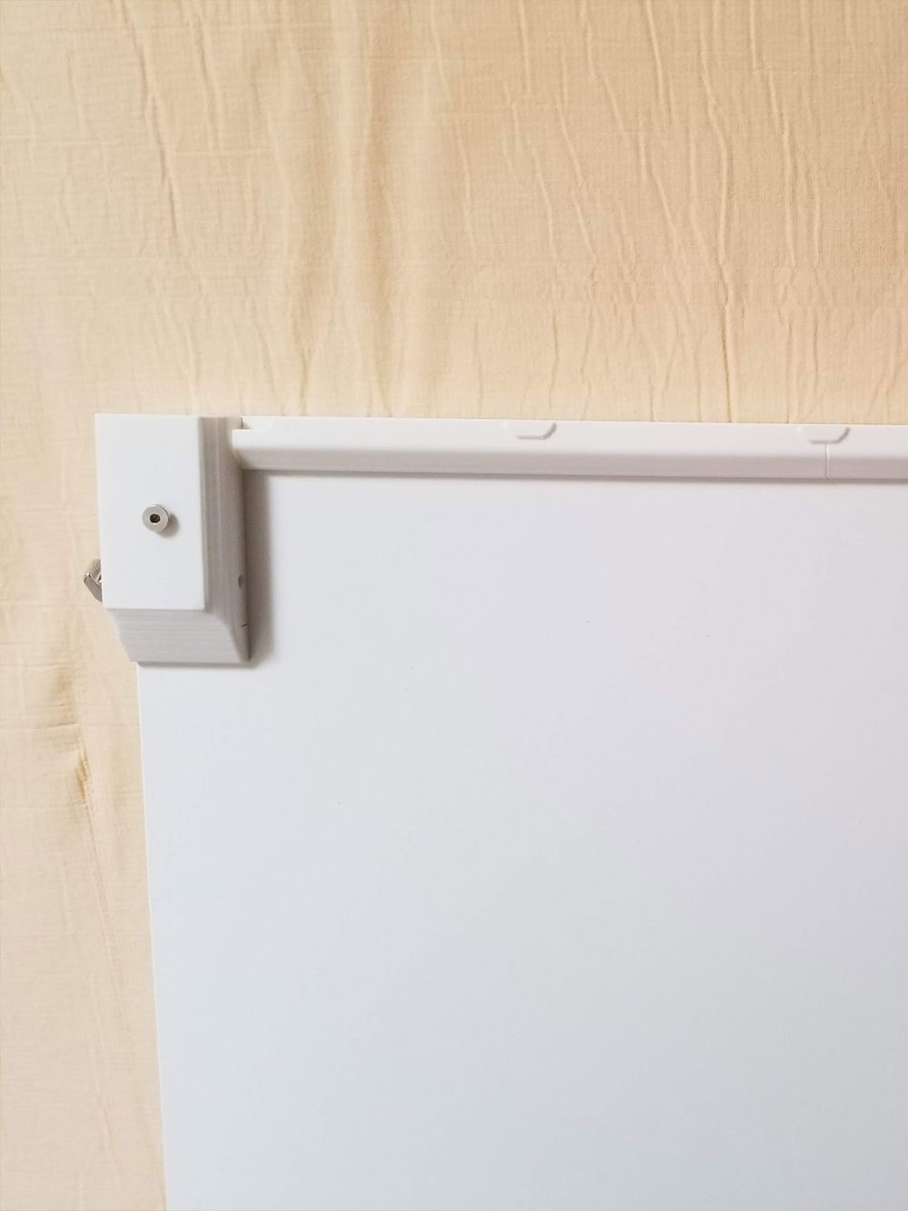
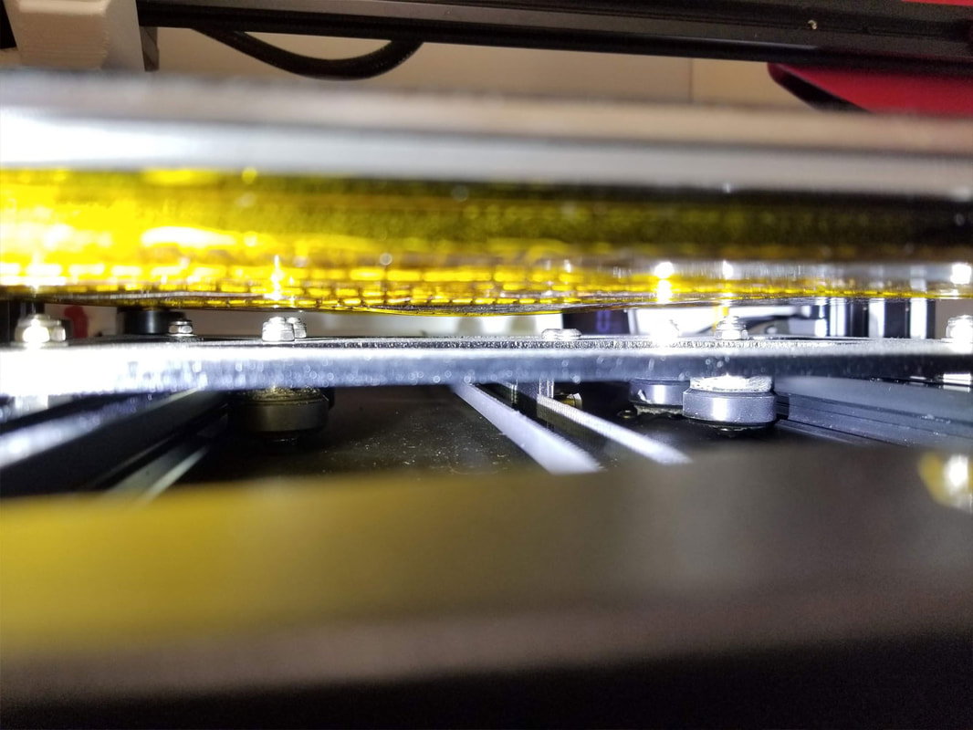
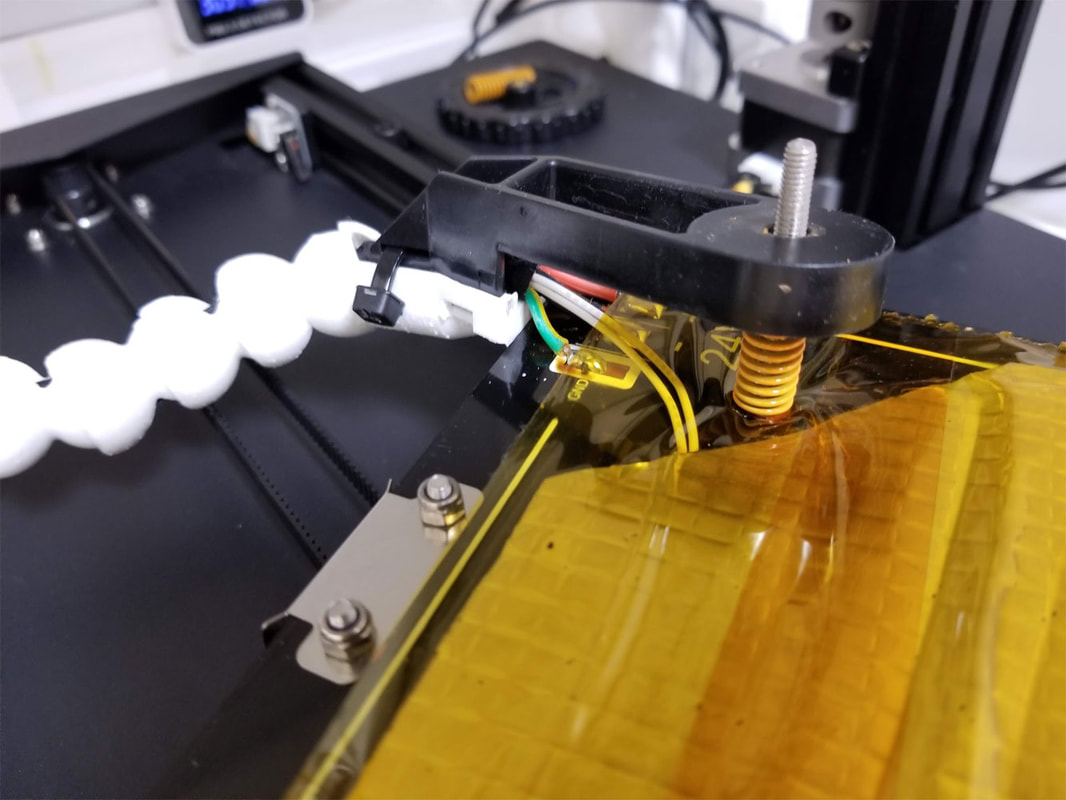
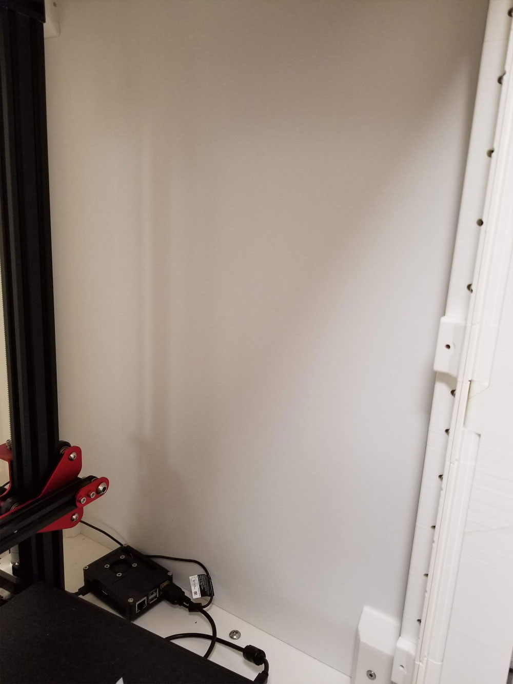
Below are some pics of the setup I used for this test.  The first set is from the Ender3 and the 2nd is from the CR10S Pro.  On the Ender3 I just unplugged the original thermistor and swapped in the 100K Ohm potentiometer in it's place using some dupont jumpers.  I first set the potentiometer to around what my thermistor read at room temp (which was around 90Kohms) so when it was connected it would not trigger any thermal protection on the printer when I first tried it.


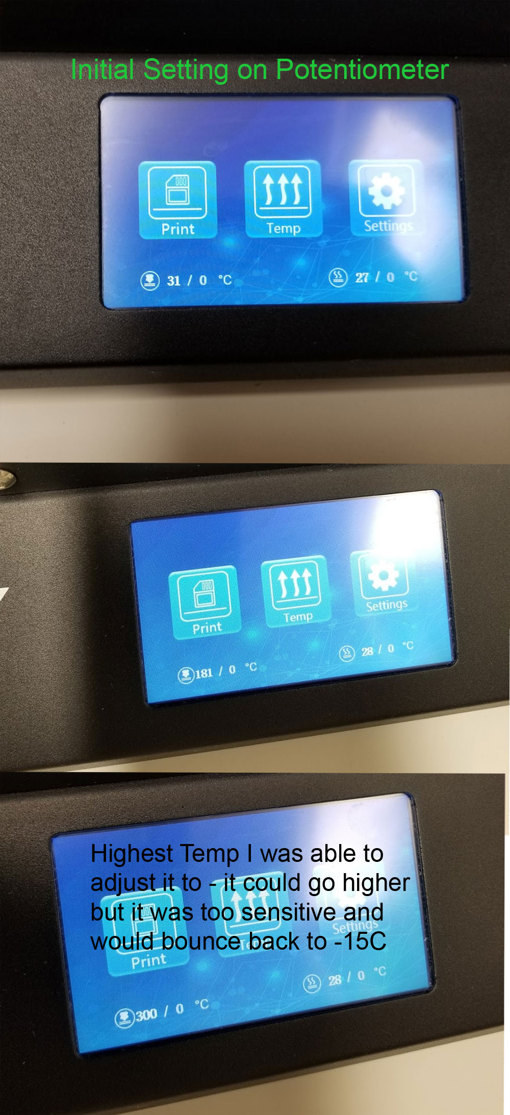
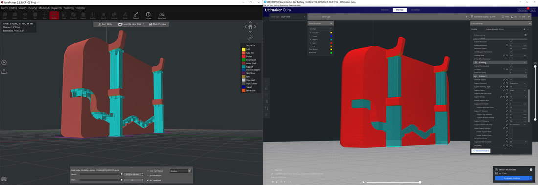
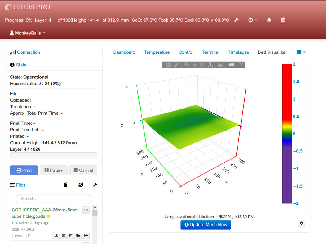
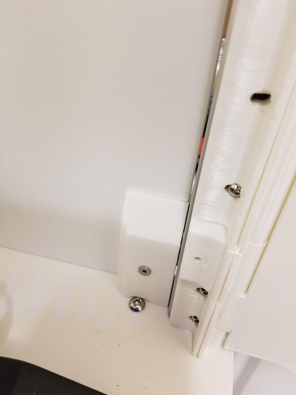
The CR10S Pro was trickier since the thermistor connects to a breakout board, and the dupont connectors did not fit (too large).  Here I took a fan connector I had and just shoved the wires into the mini breadboard I was using the the potentiometer.  It worked but was a bit clumsy, since I also jammed a couple jumpers in the breadboard to help hold the wires from the connector.  As with the Ender3, I preset the potentiometer to around 90K Ohms before setting it up.  On the CR10S Pro I noticed what is probably a software difference because adjustment of the potentiometer could cause the display to show -10C if I went to quickly which was easy since after 160C or so it was just a hairs breath of change needed to move the temps greatly (since it is a nonlinear scale and I used a linear pot).  Still I was able to get it to read 185C and as high as 300C even as touchy as the adjustment was.  When I put it back together I screwed up through and installed the thermistor in the connector which is one back from where it should have gone.  Once I fixed that though it worked as before.
This really proves nothing but I thought it was an interesting thing and may help me with testing thermistor inputs should the need arise.
0 Comments

Remix and Remix again...

7/31/2020

0 Comments

 
Picture
I thought I was done with my new Ender3 Spool Holder based on the one posted by Butchja on thingiverse, but when I went to try it with some of my Tactlink spools, I found that the spool holder was simply swallowed up because the 75mm holes on the spools were too large for the spool holder.  It was a dumb thing not not have foreseen since my old spool holder had much larger ends.  So it was back to the ViaCAD V12 Pro drawing board...  It was not a very difficult change in concept but it still took a bit longer than I had hoped, but it is done.  I hope to get it printed in the next week but in the mean time it is available as a work in progress on Thingiverse here.  The pics of the printed version are the old type which has the too-small ends, the CAD images are the new version with 80mm end pieces.  I am really happy with the function of the spool holder otherwise and it uses easy to find 5/16-18 hardware, a couple washers, a pair of 608ZZ skate bearings and a 6" threaded rod (I used a 6" dual end threaded stud).
Update, this is done and looks great, but took me much longer than I expected.  Problem was that the first try at making it large enough for a spool with a 75mm hole worked but was not really great and required making the ends slightly larger.  So it was sort of a goldilocks situation but I finally got it just right :D

You can get it here:

https://www.thingiverse.com/thing:4557471

Below are some pics of the final version:
Picture
0 Comments

A Little Calibration Can Go A Long Way

7/26/2020

0 Comments

 
Picture
My normal settings for PETG were not working too great so I re-ran some calibration things and got it tuned up.  Was really impressed with the result - no stringing! The recommended temp on this filament is 240 so I am running it a bit cooler, and it does not seem to effect the strength - but if that is a requirement, I'd probably go hotter and try using the fan.

EDIT 7-31-2020: This is still a work in progress, and I am now trying to tune the acceleration and jerk settings since my print quality has taken a bit of a nosedive, but I rarely print PETG so it may just be the difference in filaments.

Filament: Duramic PETG (white)
Temps: 233 / 70 C
Flow: 101%
Speed: 40mm/s
Fan: off
Retraction: 5.6mm @ 45mm/s (CR10S Pro with Microswiss All Metal Hotend with 0.4mm nozzle)
Combing: Not In Skin

This printer does not have linear advance since it uses the TMC2208 drivers.

Thingiverse seems to be having problems today, but I think the models were:

Smaller Base Stringing Test

PETG TEMP TOWER 230-250

Picture
Picture
0 Comments

IdeaMaker Could be an Answer to Difficult Supports

7/24/2020

0 Comments

 
Picture
I printed a test of the Black and Decker 20V Battery Charger mounts and found that, aside from an oversight which required a minor fix, the supports in the cable management channel were really well stuck.  I was able to clear them out but it was not easy.  I decided to try re-slicing with IdeaMaker which I have found does really well with supports, although I also really dislike it's UI.  Below is a comparison of IdeaMaker vs Cura supports.  The Cura supports got skinned over and are pretty dumb, but the IdeaMaker supports are much more broken up and won't be skinned over, so I can poke some tools in there to get them out.  Certainly I could spend some more time to tune things, and probably get the Cura supports to work, but I just want to get this printed and despite the poor supports the model looked mostly OK when printed (sliced with Cura).  I just started the print for the IdeaMaker sliced model and expect it to look fine, but will have easier to remove supports.  Interestingly the estimated print time was also about 15 minutes less, despite running at a slower speed.  The one difference that probably accounts for that is that I sliced with 3 walls in Cura and 2.5 in IdeaMaker (it alternates an extra line every other layer, so 2-3-2-3, etc).  I also was slicing without a support interface in Cura to make them easier to remove, but as you can see in the pic, they are still very monolithic and would very likely be skinned over again making them hard to remove.

The downside of IdeaMaker is the learning curve and it's confusing array of tabbed settings.  It is really bad, and I am still confused about which flow rate takes precedence (so I set them all the same).  If they went to a Cura style menu for settings it would be just about the perfect slicer - or if Cura could add some intelligence to their supports, it would be about perfect.  In any case IdeaMaker works when supports are unavoidable and Cura is not up to the job.  I still use Cura first though.
Picture
IdeaMaker (left) Cura (right)
0 Comments

Black and Decker 20V Battery and Charger Holders

7/24/2020

0 Comments

 
I needed to make some more battery holders for my Black and Decker 20V tools.  I also have some extended batteries which will not fit the holders I already have (and could not find when I went searching for them today.  But I did find RSGeek's Black and Decker 20V Batter Holder on Thinginverse which looks great, but there is no model for the extended size batteries.  I decided to remix (edit, it will not be a remix see below) it to fit and what was a simple 5min task turned into a whole set of battery and charger holders for the Black and Decker 20V batteries.  There are all mount and 1" peg board versions since that's what I have.  I'm printing a test now and will post them when they are good to go.

Update  7/25/2020:  The Battery Charger Mounting Clip is posted here.

I am printing an extended battery holder and will post that when I have it tested.

Update 7/25/2020 (#2):  I had the remixed holder almost printed when I read that it will not work with the charger attached to the battery.  Unfortunately I need the battery + charger to both sit in the holder, so I decided that I would need to re-design the holder and I have given up on the remix.  I will make my own holder to go with the charger holder.  I had to model a crude battery to get the dimensions about right and the new design is almost finalized.  I will post the new design once I have it tested.
Picture
Picture
Picture
0 Comments

New SpoolHolder (Remix of Butchja's "Universal Filament Spool Holder") in the works

7/22/2020

0 Comments

 
Picture
Picture
I really liked the spool holder I was using (which was a remix of Skrutt84's "Filament Holder Deluxe") but I did not like the very pointed threads.  Nothing wrong with them and they held up fine, but they just bothered me.  I also gave mine away to a buddy who was having some issues with his filament feeding (I rarely use my spool holder on the Ender 3 now that I have dry boxes with built in rollers).  So when I saw Butchja's "Universal Filament Spool Holder" I wanted to give it a try.  However, since I previously remixed Skrutt84's Spool Holder Deluxe to use a pre-cut 5/16 x 6" threaded rod, I wanted to have the same setup for the new one.  The benefit of this design is that it will be an easy and cheap no-cutting option for folks who find it harder to obtain metric threaded rods.  The pics above are what I came up with, and if it works out, I will post it up to Thingiverse soon.  It will require the following parts:

1x 5/16"-18 x 6" threaded rod (I will be using a threaded stud)
2x 5/16" lock nut
2x 5/16 x 11/16 OD washers
2x 608ZZ (skate) bearings


0 Comments

Added some more side panels to the enclosure

7/15/2020

0 Comments

 
I printed some more of the panel to 4545 extrusion connectors and mounted the sides on the base of my enclosure.  Before there were only the 4545 half round corner posts on the base.  Now I need to figure out what to do for the back and front.  Considering adding a drawer to hold the miscellaneous junk that always accumulates around my printer (currently spread out in messy style on top).  There are drawers at Ikea that would work perfectly, but their shipping time is over a month now thanks to Covid.  I could print some but they would be a bit shallow.  Also considering a door to create a smaller enclosure for my Ender3 below the big one. but more likely it will be filament storage since working on a  printer near the ground would suck.

Below are some pics.  Pardon the mess, it's still very much a work in progress.  I was able to find something to fill the gaps between the panels and the extrusions.  It is a felt tape which was not cheap, but should be enough for this whole project and then some.  However due to the thickness I was only able to apply it to one side and the bottom.

I'm also re-working the door design and may re-print one to check it out.  Still a lot to do on this and I would like to figure out a better filament storage setup (really anything is better than what I have now).
0 Comments

Bumpy Beds and How to Fix Them

7/15/2020

0 Comments

 
No this is not some tale about a Princess and a Pea, but rather a quick fix for bumps or slight resistance felt when moving the bed of a printer by hand.  I recently installed a bed cable chain by Portzal at Thingiverse on my CR10S Pro, and while installing it, I noticed some light resistance when moving the bed by hand (something I rarely do).  When I checked the wheels, they were full of lint and worn POM material from the wheels (some will need to be replaced). 

For now I just unscrewed the bed leveling knobs, and pulled the bed off (being careful not to loose the springs), an then used a microfiber cloth to clean the wheels and rails.  After that the bumps were gone.  I also re-adjusted the eccentric nuts which are on the outer wheels to tighten things up a bit more since the wheels on the left were a bit loose.  Since the bed was off, I also took a look at the connections to the heating element before re-assembling it.  Once leveled again I re-checked and it runs much more smoothly.
The new cable chain, not related to the bumpy bed except that I noticed it when installing this.  Its also a great design.
Lint and worn POM material from the wheels can be seen on the back right side wheel, this bit was causing the bumps I believe.  But all the wheels needed cleaning.
After removing the bed, but before cleaning.
Bed heater, just flipped it to check things over since it was removed.
A look at the bed heater connections.
After cleaning with a microfiber.
After cleaning with a microfiber.  These outside wheels have the eccentric adjustment nuts.
Update 11/5/2021 - I started to notice the bumps again and this time it was not a piece of lint stuck on the wheels, but rather one of the wheels itself had a problem.  I decided to get some polycarbonate wheels this time to see how they work, and went with these.  I cannot at this time say how well they will work in the long term, but they seem to be well made and operate smoothly.  I made a point to only minimally adjust the eccentric nuts this time. 

My process was to:
  1. Remove the bed and the carriage, which is much easier if the two screws which connect the carriage to the belt connector are removed first, then remove the front plate and slide the carriage off.
  2. I replaced each wheel one at a time, making sure that when the eccentric nuts were installed, they were set to be as wide as possible (to allow for maximum adjustment).
  3. When everything was replaced, I test fit it on the rails and checked which wheels were loose.  I was lucky that only one (non-eccentric) wheel was loose.
  4. To fix the loose wheel, instead of tightening the eccentric nut, I removed the bed and loosened the loose wheel, and re-tightened it by letting the carriage hang from the wheel while tightening the nut and bolt.  The idea was to move the wheel toward the edge of the carriage and hopefully tighten it up.  This worked so I did not need to make further adjustments to the eccentric nuts.
  5. Once the carriage was back in position, I re-checked each wheel and then re-installed the bracket for the belt with the two screws, and re-installed the front cover plate.
  6. Then I installed the bed, springs and knobs.  I tried to tighten each knob the same number of turns and counted them by 10's until the back left knob (nearest the power connector on the bed) was bottomed out.  Then I loosened each knob by 2 full turns.
  7. Once the bed was all back together, I powered it up and heated the bed to 60°C and homed the printer.
  8. Next I went to the manual leveling and started at the back left (nearest the bed power connector) and used a 0.2mm feeler to set that corner.  Then I went to the diagonally opposite corner and set that corner, then the front left and finally the back right.  If any corner bottoms out, raise all the knobs by a turn or two, and then re-home the printer. and repeat this process of manually leveling the corners.
  9. Then I went around to each corner one more time and re-adjusted as needed, and finally checked the center.
  10. After that I just did an ABL and saved the mesh.
Picture
0 Comments

Swapped out the Brass Anti-Backlash Nuts on the CR10S Pro with POM nuts

7/12/2020

2 Comments

 
I've been trying to tune the Z-Axis due to some fine lines that show up on larger prints, which I'm sure are z-wobble related.  They are not enough to really bother me normally, but I am thinking about re-printing the doors on my enclosure with a slightly newer design, and the prints will be tall and take a good deal of time, so I want to get them right.  Since I was gonna re-work the Z anyway, I decided to pick up some POM anti-backlash nuts which I would have bought had I known they were a thing, before I installed the brass ones.  The CR10S Pro requires the 8mm version which has 2mm pitch (goes up 2mm with each full rotation) and 4 starts (which are the number of starting threads if you look at the top of the leadscrew - a normal screw has one start).  POM has better qualities than brass for this type of thing, and should need less lubrication.  Similarly to the brass ones, I had to file a bit from one side of the nut that installs on the ribbon cable side, and used a nut and a lock nut on each screw to secure them.  The screws that hold these should not be tight, but they also cannot be loose, so it's a bit of a fiddly thing, and the lock nut should lock against the regular nut (it would go spring washer, regular nut and then lock nut).  I lost a couple of the spring washers though so not all mine have them.

I also went back over the Z-setup following the process outlined in this video.  I also found a few things during teardown which may have been contributing, specifically the old brass nuts may have been too tight and the top left bearing guide had to be scootched over just a bit to align with the leadscrew better.

I still need to test this, and will update with some pics once it is tested.

Update 7/18/2020: They work great, and I can see a slight improvement in the print quality, would definitely get these over the brass ones.
2 Comments

Finally Finished the last Wall of the CR10S Pro Enclosure

7/8/2020

0 Comments

 
One wall in my partly printed CR10S Pro enclosure has been cardboard for the past several months.  The reasons for that are many, but the most important was that I did not have a good way to secure the wall without having anything showing on the outside.  The side wall is an Ikea HÄGGEBY cabinent door which was 7 bucks and what I designed the enclosure to use (since they are an economical way to close in the sides).  I'm planning to add two more of the doors as sides on the base part of the enclosure as well, and then possibly add some drawers and maybe shelves.  Right now though, I'm just happy to finally have the top enclosure, enclosed.  I will have to take it apart however since I need to seal the edges of the walls with some felt tape. 

The wall is connected with a 2 part attachment to the 4545 extrusions of the frame.  I first attached one part to the Ikea doors with screws (7/8" wood screws), and then the other part which has a M5x20mm round head screw with a M5 T-nut attached slides into the frame and then connects with the first part.  They are finally connected with a M5x20mm flat head screw which is the only hardware that shows when it is all together.  There is also a hole to fit an allen key so the T-nut can be tightened down in it's final position.  Overall the system works but it is a bit difficult to tighten down the T-nut since it has to be done in half turns with the wrench.  The next steps will be to add some lighting, a power supply for the Pi, Lighting and filters/blowers and probably then I will focus on the base some more. 

I have not posted this up to any sites, and am not sure if I will since the files are a bit of a mess and it's gonna take a while to sort out the final designs I used, not to mention explain how it all goes together.  It's a lot of work that I am not looking forward to and don't really have the time right now to write up instructions for it.  The expense of the project is also prohibitive for most folks and I only got into it piecemeal but know it cost more than the printer it encloses.
0 Comments
    Picture

    Stoopid Me

    Welcome to my Stoopid corner of teh Internet.  It's mostly gonna be 3D printing stuff, but I also post some recipes, projects, and the occasional rant here as well.  More Stoopid stuff is updated regularly.

    I recently joined the Amazon Associate program, so some of the links on this site are Amazon affiliate links. This means that, at zero cost to you, I will earn an affiliate commission if you click through the link and finalize a purchase.  This will help to support this site, and pay for more Stoopid Stuff.

    Archives

    March 2023
    February 2023
    January 2023
    November 2022
    October 2022
    September 2022
    August 2022
    July 2022
    April 2022
    February 2022
    January 2022
    December 2021
    November 2021
    October 2021
    September 2021
    August 2021
    July 2021
    June 2021
    May 2021
    April 2021
    March 2021
    February 2021
    January 2021
    December 2020
    November 2020
    October 2020
    September 2020
    August 2020
    July 2020
    June 2020
    May 2020
    April 2020
    March 2020
    February 2020
    January 2020
    December 2019
    November 2019
    October 2019
    September 2019
    August 2019
    July 2019
    June 2019
    May 2019
    April 2019
    March 2019
    February 2019
    January 2019
    December 2018
    November 2018
    October 2018
    September 2018
    August 2018
    July 2018
    June 2018
    May 2018
    April 2018
    March 2018
    February 2018
    November 2017
    September 2017
    August 2017
    June 2017
    December 2016
    October 2016
    September 2016
    July 2016
    March 2016
    February 2016
    September 2015
    August 2015
    June 2015
    May 2015
    April 2015
    March 2015
    February 2015
    January 2015
    December 2014
    November 2014
    October 2014
    September 2014
    July 2014
    June 2014
    May 2014
    April 2014
    March 2014
    February 2014
    November 2013
    August 2013
    July 2013
    June 2013
    May 2013
    April 2013
    March 2013
    January 2013
    December 2012
    November 2012
    October 2012
    September 2012
    August 2012

    Categories

    All

    RSS Feed

      Contact Form (Name is optional)

    Submit
Powered by Create your own unique website with customizable templates.