One of the corners on my delta had a small crack which was probably nothing to worry about, however I had noticed that the bed was difficult to get square to the side posts (actually it was not possible to get square since the side posts had a slight tilt to the inside. Since I would need to disassemble most of it to correct that fault I decided to upgrade the corners with aluminum extrusions. There are 2 types of aluminum corners which I had found online. I bough the cheaper ones from Ebay which seem to work fine. The corners I would have bought if they did not cost as much for shipping as the parts themselves, were the corners from RobotDigg, since they appear to be milled on several surfaces and overall better designed (they utilize flange bearings for the rollers also which is some added cost). The cheap-o aluminum corners on Ebay however seem to be just fine, though they are a pain in the ass to assemble due to the poor design for tool clearance (this was a problem with installing the motors). Funny thing is that the pics on some of the Ebay auctions for the corners show them missing holes and with wavy extrusions, though mine were fine in the regard (they probably took the pics of some pre-production models).
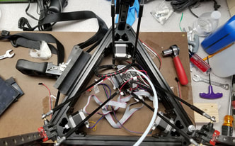
To avoid the screw ups of my initial assembly I put some thought into how I was gonna put this together the 2nd time around. I decided that I needed to first get a flat surface to hold the corners against, for this I used some old MDF with a piece of that brown pegboard material without the holes (sorry can't recall the proper name). Really I just needed something flat and strong enough to pass bolts through. After that I loosely assembled the new corners to the 2020 extrusions making sure not to tighten anything down. I used the loosely assembled base as a template, and marked 3 holes, nothing had to be perfectly accurate at this point, just 3 holes per corner, with one each using the two holes in the corner parts, and another in the square hole so I could pass the limit switch wires though the board (otherwise they would get squished - or I would need to remove the wires from the vertical posts). Next I stacked the bottom frame, then the top frame, and installed the corner posts though both without tightening anything (here is where I had to pass the limit switch wire through the hole in the board). Then I installed bolts through one of the two holes in each of the corner pieces (I did not have enough so only used 1 through bolt per corner) - these bolts were only loosely tightened also. Next I used a ratcheting tie down strap to cinch up the slack in the frames, and had to use some plastic plates I had around to keep from marring the frames and take up some of the slack since the ratcheting strap does not have a fine enough adjustment. Once the frames were cinched up, I then tightened the bolts that held the corners to the board, which should bring the frames as close to perfectly parallel to each other as needed here. After the bolts were tightened, I checked the 2020 rails to make sure they were positioned similarly in relation to the corners and adjusted as needed (this is more cosmetic, though the top rails for the base should be as close to identically spaced with respect to the corners as possible since they will mount the bed leveling clamps). After the rails were positioned and it looked good, I finally began to tighten the screws that hold the 2020 rails to the corners, doing the vertical posts first. Some of the screws were not possible to tighten so I just got all the ones I could reach and made sure they were as tight as reasonably possible before removing the frames from the board. One other thing that would have helped me here would be using better M4 T-nuts. The nuts they used to assemble the frame at the factory are just square nuts, which have a nasty tendency to wedge into the slots rather than spin into position and hold like a clamp. It is hard to tell if this happens unless the screw is backed out and does not wobble around (meaning the square nut got wedged). If I had them, I would have replaced all the square nuts with t-nuts beforehand.
The final step was removing the frames from the board, and the rails, and then tightening the remaining screws that I could not reach before and then re-assembling the frame. The result was that the top and bottom frames are now parallel to each other and since I set the vertical rails each at 60mm between base and top, each side post should have set the top and bottom frames the same distance from each other in each corner. Now when I square the build plate to the side posts I no longer see what appears to be a tilt to the inside on each post, they are nearly square as I can see (using a machinist square). I pretty sure the aluminum corners will also help with the rigidity of the printer as well.
I also ended up breaking a limit switch sometime during this process, so was fortunate that I was watching it closely when I re-leveled it the first time.
The one major problem with the cheap aluminum corners is the lack of space for tools, which makes installing the steppers a real pain. I had to cut down an Allen key to get the necessary clearance and start the screws using my pinky fingers which was not fun. If they had drilled some access holes it may have been at least possible to start them with an Allen key but I suspect that whoever designed these did not actually test them in use. That said, they do work and all the holes are where they need to be, including the holes for the pulleys and the hole for the nut used for the top stop.
One final note - the stock m3 screws used for the pulleys with the original Anycubic frame were not not long enough for the new aluminum corners, so I had to get some longer bolts. I think they were M3x25mm bolts that I needed to use (the originals were M3x20mm).


 RSS Feed
