UPDATE 6/19/2019 - Not digging the auto leveling on a Delta (works great on a Cartesian though). The trade offs with an offset probe on a circular bed seems to cause some problems for my setup. Right now I just want to get it working so am gonna revert to a removable zero offset probe. Will leave this stuff here though since it can apply to a Cartesian printer or folks that want to try it on a delta.
This post is updated on 9/25/2020.
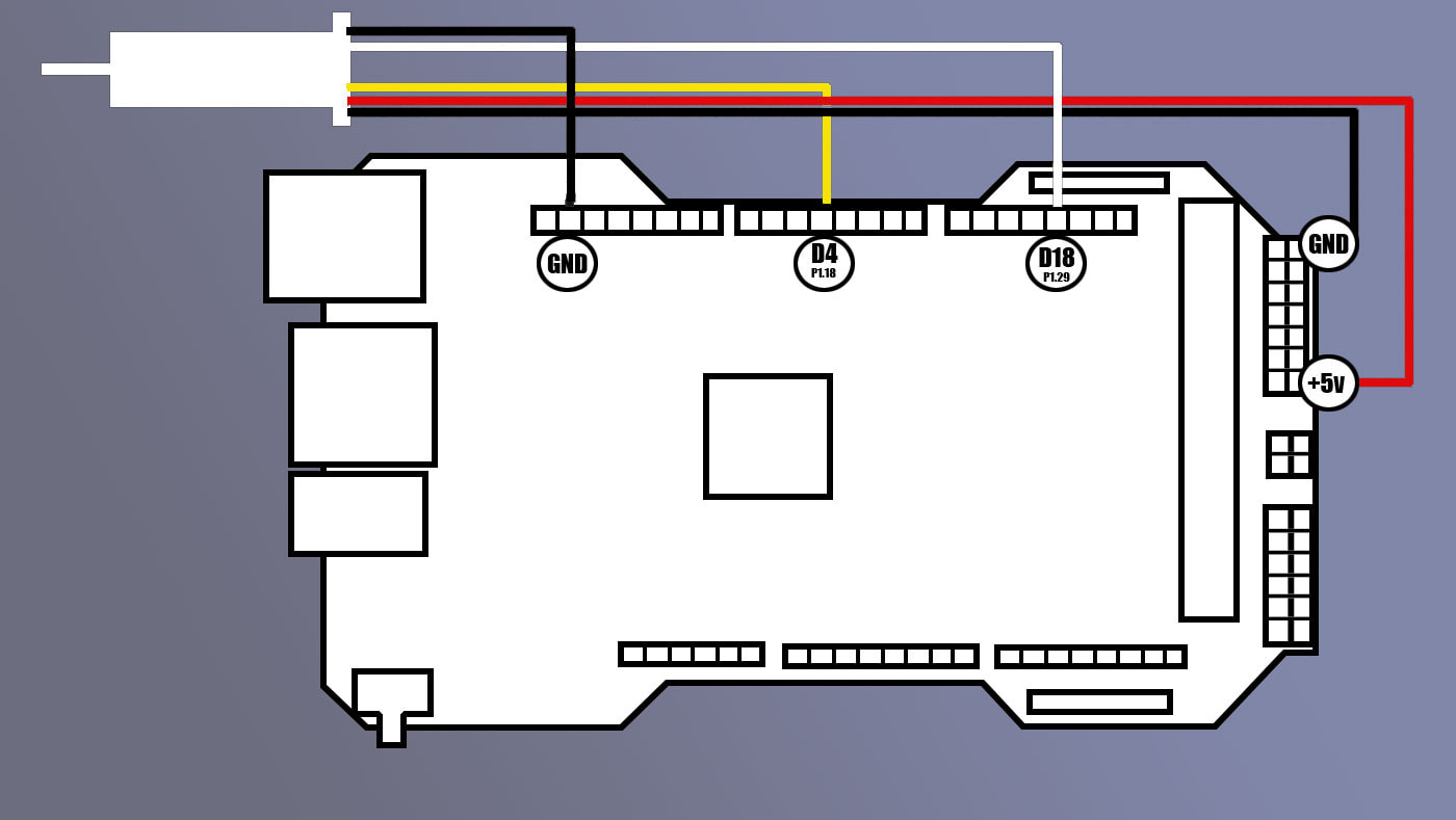
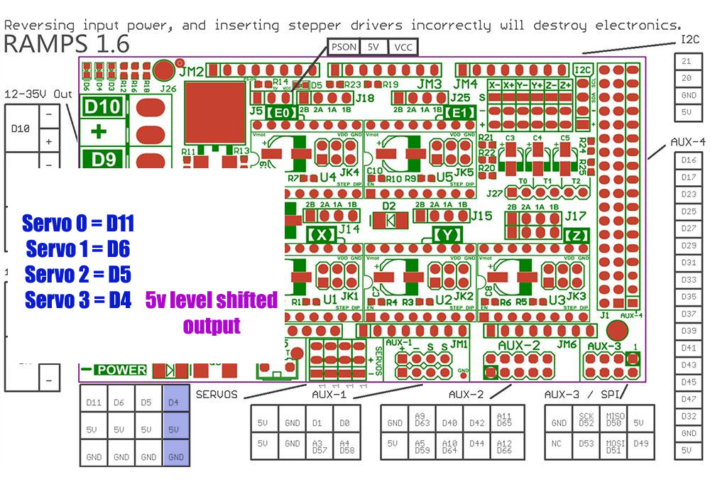
I want to add a 3D Touch probe to my Re-ARM board. The Re-ARM is a 32 bit RAMPS compatible board which was designed to be a (nearly) drop in replacement for an Arduino 2560, however it is not really that simple in practice. There are two things that I think need to be done differently than a regular RAMPS setup with a BL-Touch when using the Re-ARM. The first is that the the normal pin that would be used for the probe is Servo 0 (D11) does not have a 5v level shifted output on the Re-ARM (at least as far as I could find). Fortunately the digital pins (for the white wire on the probe) are all 5v tolerant on the Re-ARM for the input (it is just the analog pins which are not all level shifted).
Back to figuring out the 5V servo pin out; Servo 3 (Pin D4) does have a 5V level shifted output according to the docs. The probe may work with 3.3V out, I'm not sure (would say no as the 3D touch is 5v only), but I would rather just use a servo pin that can send 5V to reliably trigger the BL Touch.
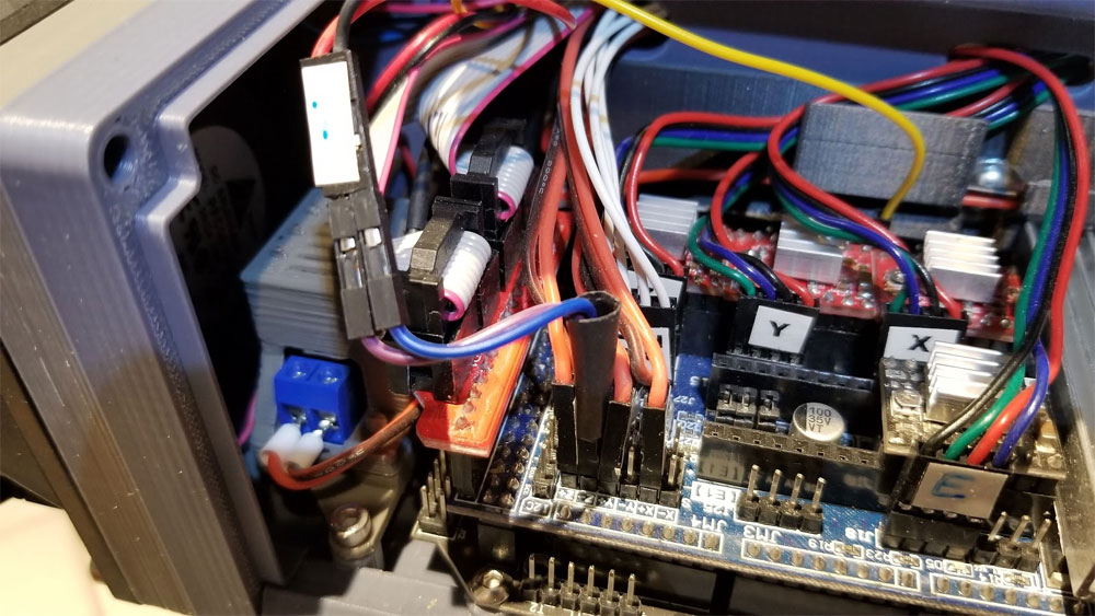
The second problem is that the 3D touch was not reliable when I tested it with the onboard 5V from the Re-ARM as shown below. It seemed that the coil would energize and hold the magnet on the probe, but then it would drop it, and I noticed that the display LDC backlight would dim when the probe was operating.
This post is updated on 9/25/2020.
I want to add a 3D Touch probe to my Re-ARM board. The Re-ARM is a 32 bit RAMPS compatible board which was designed to be a (nearly) drop in replacement for an Arduino 2560, however it is not really that simple in practice. There are two things that I think need to be done differently than a regular RAMPS setup with a BL-Touch when using the Re-ARM. The first is that the the normal pin that would be used for the probe is Servo 0 (D11) does not have a 5v level shifted output on the Re-ARM (at least as far as I could find). Fortunately the digital pins (for the white wire on the probe) are all 5v tolerant on the Re-ARM for the input (it is just the analog pins which are not all level shifted).
Back to figuring out the 5V servo pin out; Servo 3 (Pin D4) does have a 5V level shifted output according to the docs. The probe may work with 3.3V out, I'm not sure (would say no as the 3D touch is 5v only), but I would rather just use a servo pin that can send 5V to reliably trigger the BL Touch.
The second problem is that the 3D touch was not reliable when I tested it with the onboard 5V from the Re-ARM as shown below. It seemed that the coil would energize and hold the magnet on the probe, but then it would drop it, and I noticed that the display LDC backlight would dim when the probe was operating.
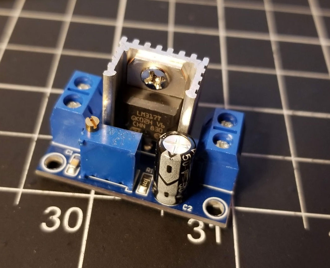
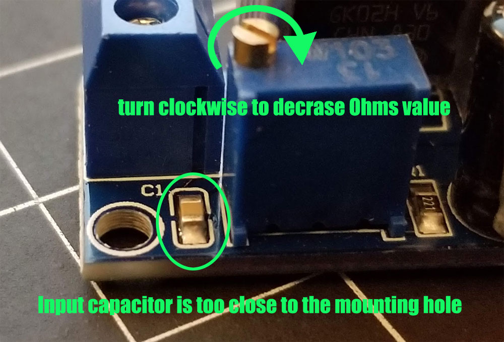
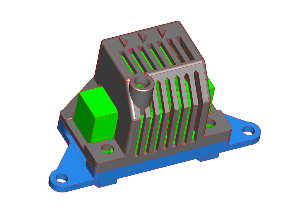
I've read that adding a 5V linear regulator like an LM7805 has helped with this problem on RAMPS 1.4 boards, and there was a simple mod for that. However on the RAMPS 1.6 board I am using, there is no jumper for the Servo 5V power rail (it appears to be just connected to the onboard 5V regulator). I plan to add an external 5V regulator which will run off the same 12V supply as the rest of the printer, and supply the 3D Touch probe, but waiting on parts for that. (UPDATE the 5v external regulator works fine). My WT-LC case has a place for mounting something like this behind the board, so I made a small mount for it which will put the regulator between the fan and Re-ARM + RAMPS (you can find it at thingiverse).
 |  |
Something else that I added, and is not shown in the pic above, is a 10KOhm resistor across the black and white wires (which go to the Z-min endstop on the RAMPS). They provided the 10KOhm resistor with my 3D Touch probe, but there were no instructions that I could find to describe what it was for. I found a discussion about it which inferred it would be used the same way as the resistor on the BLTouch which has a 640ohm resistor for this purpose. Adding the resistor seemed to help a bit with the stability of the connection, just wish it was better documented.
The last thing which has been a problem for me, is understanding the way the servos are numbered in Marlin. They start at zero and go to three:
The last thing which has been a problem for me, is understanding the way the servos are numbered in Marlin. They start at zero and go to three:
I needed to add the following to get Marlin to compile (this config works OK with my setup - which is a modified Anycubic Kossel Linear Plus) - NOTE I AM USING SERVO 3 FOR THE PROBE (D4 on the Re-ARM).
#define BLTOUCH
#if ENABLED(BLTOUCH)
#define BLTOUCH_DELAY 750 // Minimum Command delay (ms). Enable and increase if needed
#define Z_PROBE_SERVO_NR 3 // Defaults to SERVO 0 connector.
#define Z_SERVO_ANGLES {10,90} // Servo Deploy and Stow angles
/**
* BLTouch V3.0 and newer smart series
* For genuine BLTouch 3.0 sensors. Clones may be confused by 3.0 command angles. YMMV.
* If the pin trigger is not detected, first try swapping the black and white wires then toggle this.
*/
//#define BLTOUCH_FORCE_5V_MODE
//#define SERVO0_PIN P1_18
#endif
#define SERVO_DELAY {300,300,300,750} // This is needed to get BLTouch working on Servo pin 3 (4th servo)
#define USE_ZMIN_PLUG // I am connecting the probe to the z-min endstop
// Mechanical endstop with COM to ground and NC to Signal uses "false" here (most common setup).
#define X_MIN_ENDSTOP_INVERTING false // set to true to invert the logic of the endstop.
#define Y_MIN_ENDSTOP_INVERTING false // set to true to invert the logic of the endstop.
#define Z_MIN_ENDSTOP_INVERTING true // set to true to invert the logic of the endstop.
#define X_MAX_ENDSTOP_INVERTING false // set to true to invert the logic of the endstop.
#define Y_MAX_ENDSTOP_INVERTING false // set to true to invert the logic of the endstop.
#define Z_MAX_ENDSTOP_INVERTING false // set to true to invert the logic of the endstop.
#define Z_MIN_PROBE_ENDSTOP_INVERTING true // set to true to invert the logic of the probe.
#define Z_MIN_PROBE_USES_Z_MIN_ENDSTOP_PIN
Note that SERVO_DELAY had to be added, and also had to be an "array" with the same number of elements as the number of servos. The way I read it is like this:
#define SERVO_DELAY { SERVO_0_DELAY, SERVO_1_DELAY, SERVO_2_DELAY, SERVO_3_DELAY }
There was no "NUM_SERVOS" defined in my config, I guess that it figures that out on it's own based on the "PROBE_SERVO_NR 3". There seems to be several entries that have been depreciated or changes since I last set up Marlin using Atom.
The "BLTOUCH_DELAY 750" was changed due to a suggestion I found in the marlin forums. I also set the value of 750 in the "SERVO_DELAY" to keep it consistent (hopefully).
Once I get this all tested I will update this post with what was done, and some pics of the setup. UPDATE - this is tested and the probe works, the problem I now have is with the probe hitting the bed clamps since it is an offset probe on a delta printer.
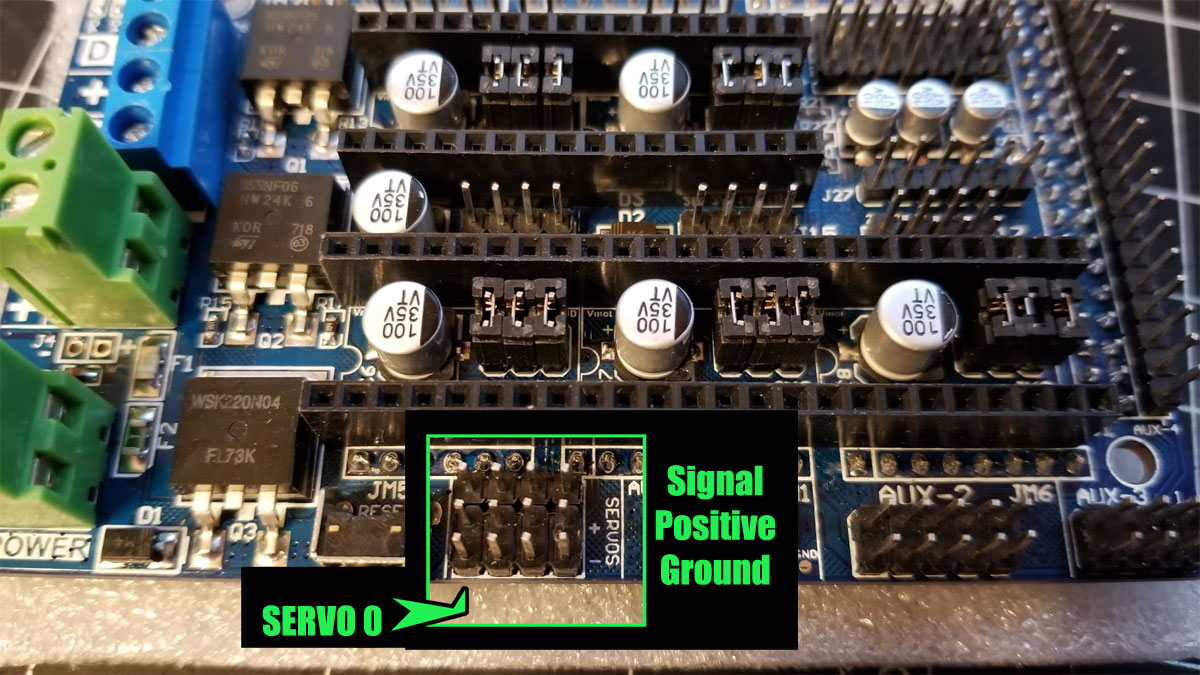
9-26/2020 Below is a pic of a spare RAMPS 1.6 board showing the servo pins (for Venu in the comments below)


 RSS Feed
