https://markforged.com/resources/blog/heat-set-inserts
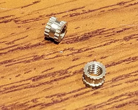
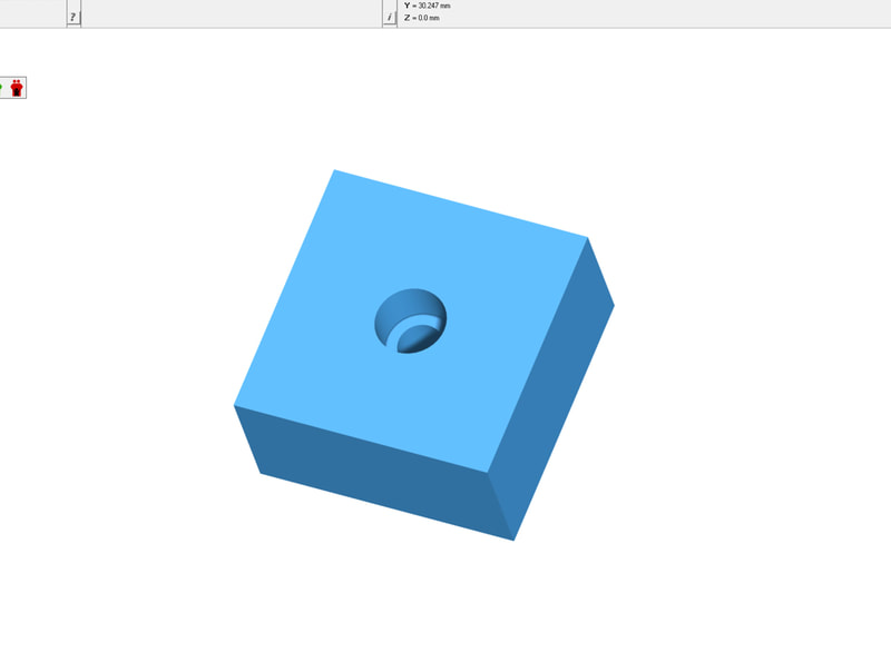
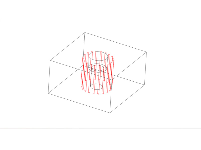
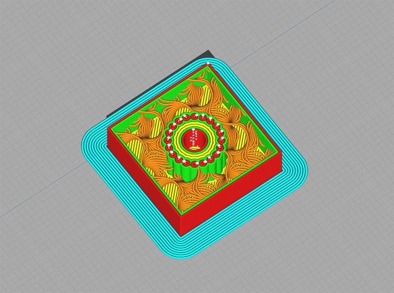
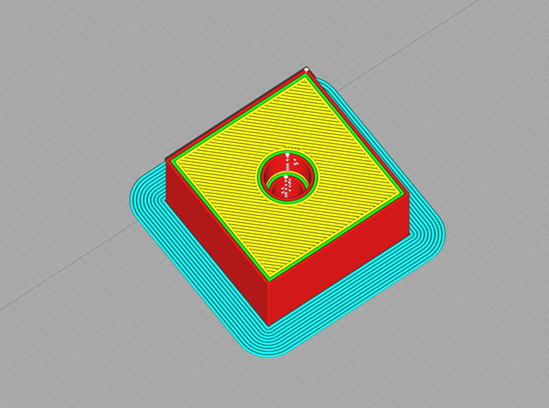
It was mentioned in the article that using additional re-enforcement around the hole will help. The way I have done this when designing parts using heat set inserts (or even for through holes intended for use with bolts), is to add some slicer independent thickening of the space around the holes. To do that, I will add an array of through or almost through holes, with a very small diameter (0.4mm or the nozzle diameter is enough). These holes are placed at a distance from the hole equal to about 1.5-2x the estimated wall thickness. So for a wall of 0.4mm x 2 lines (or 0.8mm walls), I'd place the holes around 1.2-1.6mm from the holes. This way the holes will create an almost solid area around the hole and provide extra strength to the part. It allows the rest of the part to be printed with lower walls and less infill, since using just 2 walls may not provide enough side support to the insert once it is melted in place. The holes can be placed so they will not show on the surface, by burying them just below, so the top layers will seamlessly go over them. This same technique can be used to add internal bolstering to a model, but it should be anchored to a wall or surface so it will not free float in the infill.
One caveat to using this method is that slicers may ignore the holes depending on settings for things like nozzle diameter and wall thickness. So it helps to know what nozzle size is planned to be used, and an idea of how many walls and surface layers may be used in printing the part. If in doubt, making the holes slightly larger should get them to show up in the slicer.


 RSS Feed
