Upgrades:
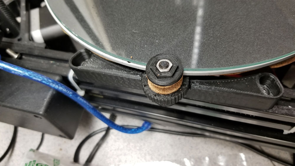
- 240mm x 3mm Round Borosilicate Glass Plate
- Screw down bet clamps
- Cork insulation of the heated bed
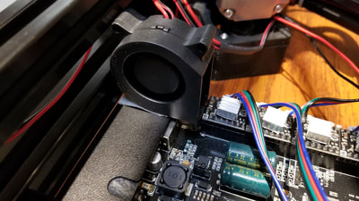
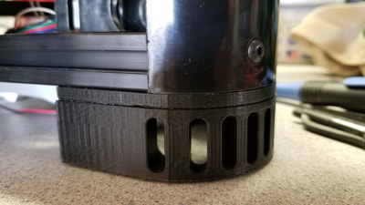
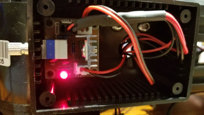
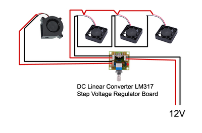
- Fan feet and a fan to blow over the stepper drivers with a control box using a LM317 and pot to control the speed.
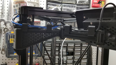
- Monitor arm for the OctoPi running TouchUI (may reprint this in ABS if I get those settings figured out)
Planned upgrades:
- Aluminum corners (possibly) - noticed some dimensional issues with the frame, not bad, but still not great.
- control and stepper board upgrade
The glass plate is a great upgrade, but can make it difficult for printing ABS, had a hard time getting it to stick, but finally was able to with the following settings:
Monoprice ABS+ Blue
--------------------
Printer Temp 240
Plate Temp 85
Cooling off
Speed 30/60
Adheasive Purple Glue Stick full strength
Notes Z height at -15.82, with Brim
Where the glass plate really shines is with PLA. I just spritz it with some hairspray every few prints and prints hold tight when it is hot and slide off when it cools. The settings below are probably conservative for the speed but that's where I am at right now with the printer.
PLA
Monoprice PLA+ Black or White
--------------------
Printer Temp 195-200*
Plate Temp 60
Cooling on
Speed 40/80
Adheasive Hairspray
Notes Z height at -15.72, with Brim
*ran into a problem with supports fusing at 200, so dropped it to 195 on the white PLA.
Calibration:
I was gonna go for the Marlin upgrade but read that I may have difficulty finding the latest firmware for the printer if I decide to go back. After some more reading I decided to go with a RAMPS board and RE-ARM 32 bit processor. I also have some TM2206 stepper drivers from some time back and so that will be my next project - getting all that working with Marlin. I have a Marlin configuration.h also set up and have some additional tweaks from the calibration hexagon explained here. These are not yet tested since I am still running the Anycubic stock firmware, but hopefully these will work, or I can re-do them to get the values - will need to re-do them anyway if/when I replace the corners eventually.
====================================== NOT TESTED
From the printed 75mm per side hexagon in the Thingiverse link, I have the following measurements:
Delta Radius = 134.4
Delta Rod Length = 271.5
X = 74.950
Y = 75.430
Z = 75.080
Plugged those into the spreadsheet here:
https://docs.google.com/spreadsheets/d/1HcnZ0aDC2wujHhPHVeYFcPekEpY6Y4wLSMfCxJ18e1o/edit#gid=1292102991
Results - to add to the Marlin Configuration.h:
DELTA_DIAGONAL_ROD 271.864
DELTA_DIAGONAL_ROD_TRIM_TOWER {-0.483, 0.657, -0.174}
Additionally I will need to send the following to the printer after flashing (M500 is to save the value):
M665 L271.864
M500
======================================
Extruder Calibration - referenced the following site:
mattshub.com/2017/04/19/extruder-calibration/
Asked printer to extrude 100mm
G1 E100 F100
Measured resultant filament as 98mm actually consumed.
Found the steps per mm using the M105:
Send: M105
Recv: ok T:109.2 /0.0 B:63.5 /0.0 @:0 B@:0
Send: M503
Recv: echo:Steps per unit:
Recv: echo: M92 X80.00 Y80.00 Z80.00 E96.00
"E96.00" means 96 steps per mm for the Extruder.
100/98 x 96 = 97.96
The new steps per mm for the extruder is 97.96. Send the following to the printer to set the value in EEPROM (M500 is to save the value) - I could round up or down, but went down:
M92 E97.9
M500
======================================


 RSS Feed
