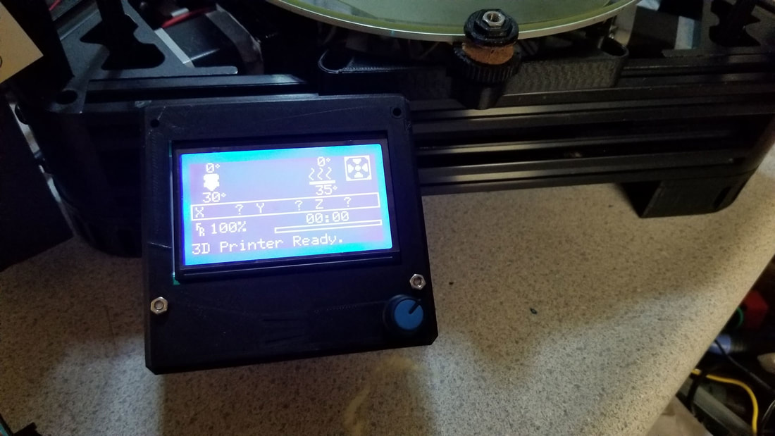
1. Auto Home
2. Move the nozzle down to the bed and use the paper method or a feeler gauge to set the probe offset. I found that my new zero was -0.7mm lower than previous so I changed the probe offset:
was:
M851 Z-15.21
changed to:
M851 Z-15.91
3. Save the settings with M500
4. Auto Home
5. Set up the level probe and run an auto-level
G33
6. Save the settings with M500
7. Move the nozzle down to the bed and use the paper method or a feeler gauge to verify the probe offset is correct. If it does not zero at the correct spot and a change is needed, repeat all the steps again.
8. PID Autotune (nozzle), here I used 215 degrees C and 8 iterations to test with, M106 sets the fan to full:
M106 S255
M303 E0 C8 S215
9. Use the settings the autotune provides (which will be on the terminal) to update the settings.
ex:
Recv: #define DEFAULT_Kp 15.24
Recv: #define DEFAULT_Ki 1.14
Recv: #define DEFAULT_Kd 50.96
so set them like this:
M301 P15.24 I1.14 D50.96
10. Save the settings with M500
11. Verify the settings for PID and the z-probe offset using M501
There is another "hack" or tweak that can be done if the height is still off after all this. The delta height value can be modified but if that is done, the probe offset should also be adjusted by the same amount so the next time the autolevel is done, things will not change.
Ex - here the nozzle is smooshed too much into the bed, so this will raise it up by 0.1mm - decrease the delta height and also decrease the probe offset by 0.1mm:
M851 Z-15.91
M665 L271.86 R134.91 H278.50 S160.00 B93.00 X0.37 Y-0.03 Z-0.33
NEW:
M665 L271.86 R134.91 H278.40 S160.00 B93.00 X0.37 Y-0.03 Z-0.33
M851 Z-15.81
12. Next I calibrated the steps per mm for the extruder, there is a good guide for that at the link below:
https://mattshub.com/2017/04/19/extruder-calibration/
13. Lastly, I ran a calibration hexagon to adjust the Delta Rod length and Delta Diagonal Rod Trim Towers values (I had the DELTA_DIAGONAL_ROD_TRIM_TOWER zero'ed out prior to running this for the first time, but if not those values can be entered in the spreadsheet to compensate). It may take a couple iterations to get it perfect. Also note that the expected dimension on the calibration object (L) is 75mm if using the model linked below:
https://www.thingiverse.com/thing:1274733
Then I ran the measurements though this spreadsheet to get the adjusted values:
https://docs.google.com/spreadsheets/d/1HcnZ0aDC2wujHhPHVeYFcPekEpY6Y4wLSMfCxJ18e1o/edit#gid=1292102991
Finally, I added the adjusted values to the Marlin Configuration.h file and re-compiled a new firmware with that update. It may be worthwhile to re-run this if you find that the flow for the filament being used needed to be adjusted (and that is corrected, then re-run the calibration object).


 RSS Feed
