UPDATE 8/21/2020: This will not work as planned, using the RM4 Smart Relay. I should have read the instructions more closely (or really at all since this was such an obvious oversight) - They say:
"The RM4 is 120V AC powered, and must be installed in a junction box. It does not work without AC power or during a power outage."
That said, I am now the proud owner of a UL listed 120V relay, sure I will find some use for it, but at least I did not pay full price. I did test my smoke detector though and when it runs on a 9v battery it puts out between 6-7volts when measured between the signal and hot or signal and ground. That is enough to power the IOT relay, but I will either need to find a place for that in my enclosure or I will need to find another opt-isolated 120V relay board to use with this arrangement.
Original Post:
There are some cool designs on Thingiverse for a Smoke Detector Cutoff for a 3D printer as an extra layer of protection in the event the worst occurs. The best I have seen are HenryArnold's design here which uses an IOT relay, a couple power supplies, some diodes and a off the shelf smoke detector (hardwired). The benefit of this design is that it is mostly using components that plug in with very little soldering. The downside is that it has several points of failure (power supplies and the IOT relay). It is a pretty brilliant design though, and it is all low voltage. The other design I really like is NikDFish's design which utilizes off the shelf smoke detector and relay parts. His design really utilizes the hard wired smoke detector in a configuration that was intended, with an off the shelf smoke detector relay used to control the printer power. The only downside there is that the detector is going to run on 120VAC and that means running that into the printer enclosure. I would much prefer to keep things low voltage if possible. There are apparently 12/24VDC hard wired smoke detectors but they are very expensive and I don't think they have the required alarm outputs. I think the way I may go is with a hybrid approach using the best of both of these designs. I hadn't planned on working on a new design and still may not (I really don't like soldering), but the more I thought about what I'd like to have, the more I thought it may be worth the effort. Like most of my projects though, there is a good chance I will get distracted by a squirrel or something and sideline it, but if that happens I will probably use one of the well tested designs mentioned above.
What I want from the system is:
The smoke detector options I am looking at using are:
First Alert BRK 7010B Hardwired Smoke Detector
First Alert BRK 3120B Hardwired Smoke Detector
And I also plan to use this Smoke Detector Relay (Update 8/21/2020 - this will not work since it only operates on 120VAC):
First Alert RM4 Smart Relay
Basic instructions for the RM4 Smart Relay
UPDATE 8/22/2020 - The Sonoff Mini WiFi looks interesting but is not ideal since it relies on software to trigger the relay based on the GPIO. Still I may use it for this project since it has smart features, and offers the possibility to add some more inputs. I plan to test the smoke detector out to the logic level inputs on the Sonoff Mini via an optoisolator board. This does make things a bit more complicated, and I may still just use an relay board with an opto-isolator like I already have, but even if I do, I could use the Sonoff in series with it so I can power things on or off using the Octopi, or find some other use for it.
I really like the BRK3120B since it has the dual sensors, but I already have a BRK7010B photoelectic around here somewhere, so I may just use that. The only major difference that will affect my plans is the battery voltage on the BRK7010B is 9v and the BRK3120B uses 2xAA batteries (3V). In either case, I plan to power the detectors using their battery backup circuits which would be wired into the appropriate DC regulators, with a backup battery that will go online in the event that the DC regulators fail.
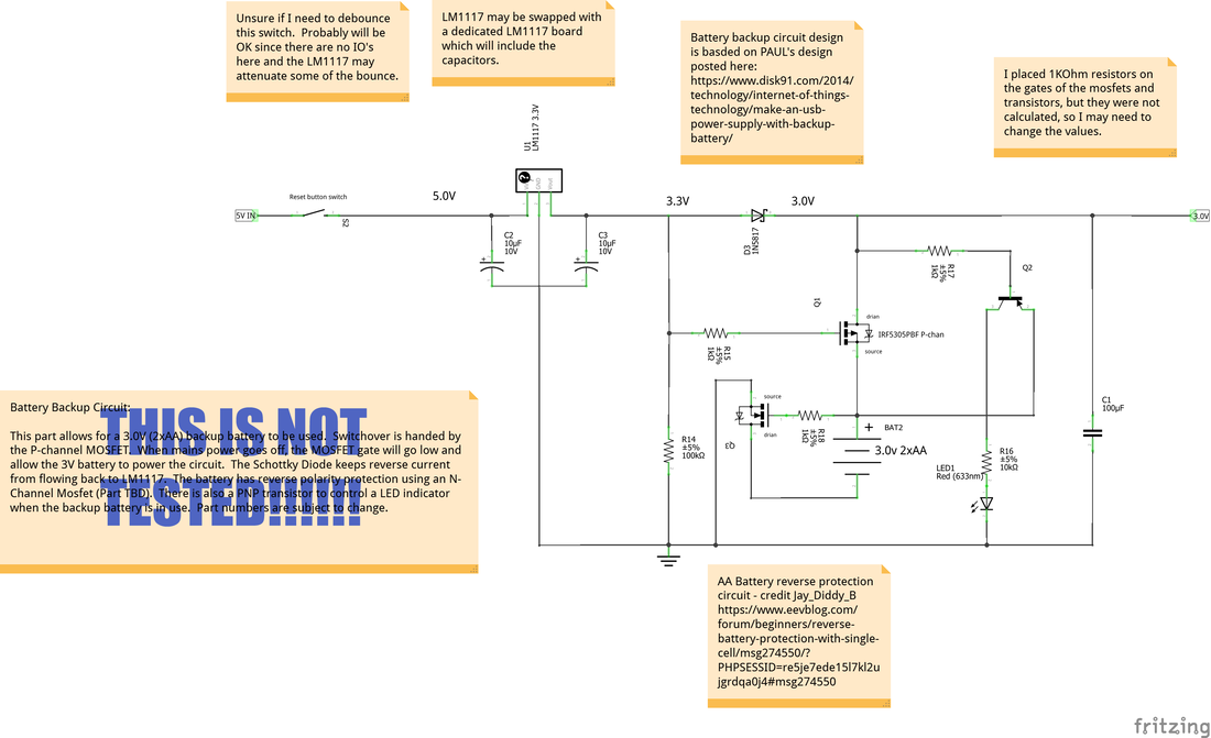
My current plan is to break the project up into two parts. The first is the input power, battery backup, battery indicator LED and the battery reverse polarity protection. The more difficult of these to do will be the 3V system since there are fewer volts to work with, but I made a schematic which I need to test out (below), that should include all the things I need. Note the resistor values are going to change and this is a rough draft - has not been tested. Also, I am no expert so I will probably fumble my way through this project. If I go with the 9V system it will be a bit simpler with just a diode for the reverse protection and I will swap the input for 12V with a 9V DC-DC regulator after that. I already have tested the 9V battery backup setup and with some tweaks it could probably work here also.
"The RM4 is 120V AC powered, and must be installed in a junction box. It does not work without AC power or during a power outage."
That said, I am now the proud owner of a UL listed 120V relay, sure I will find some use for it, but at least I did not pay full price. I did test my smoke detector though and when it runs on a 9v battery it puts out between 6-7volts when measured between the signal and hot or signal and ground. That is enough to power the IOT relay, but I will either need to find a place for that in my enclosure or I will need to find another opt-isolated 120V relay board to use with this arrangement.
Original Post:
There are some cool designs on Thingiverse for a Smoke Detector Cutoff for a 3D printer as an extra layer of protection in the event the worst occurs. The best I have seen are HenryArnold's design here which uses an IOT relay, a couple power supplies, some diodes and a off the shelf smoke detector (hardwired). The benefit of this design is that it is mostly using components that plug in with very little soldering. The downside is that it has several points of failure (power supplies and the IOT relay). It is a pretty brilliant design though, and it is all low voltage. The other design I really like is NikDFish's design which utilizes off the shelf smoke detector and relay parts. His design really utilizes the hard wired smoke detector in a configuration that was intended, with an off the shelf smoke detector relay used to control the printer power. The only downside there is that the detector is going to run on 120VAC and that means running that into the printer enclosure. I would much prefer to keep things low voltage if possible. There are apparently 12/24VDC hard wired smoke detectors but they are very expensive and I don't think they have the required alarm outputs. I think the way I may go is with a hybrid approach using the best of both of these designs. I hadn't planned on working on a new design and still may not (I really don't like soldering), but the more I thought about what I'd like to have, the more I thought it may be worth the effort. Like most of my projects though, there is a good chance I will get distracted by a squirrel or something and sideline it, but if that happens I will probably use one of the well tested designs mentioned above.
What I want from the system is:
- Uses off the shelf smoke detector and smoke detector relay components (Update 8/21/2020 this does not appear possible right now)
- Requires no, or minimal changes to the smoke detector or other off the shelf components.
- DC powered only
- Battery backup in case the mains power supply goes out
- Latching relay output (to keep the printer shut down)
- A logic level (5v/3.3v) output which goes low when the alarm is triggered (future expansion or smart home integration) - Update 8/22/2020 The Sonoff Mini Wifi should cover this if I use it
- (low priority) A 9v or 12v output that latches high when the alarm is triggered (for lights or an additional siren).
- (low priority) A 2nd alarm input option to kill power using the relay (the thought was to have the ability to connect another detector or a temp sensor that would trigger it to power down).
The smoke detector options I am looking at using are:
First Alert BRK 7010B Hardwired Smoke Detector
- Photoelectric
- 9V battery
- Hardwired
First Alert BRK 3120B Hardwired Smoke Detector
- Photoelectric and ionization sensors
- 3V (2xAA) battery
- Hardwired
And I also plan to use this Smoke Detector Relay (Update 8/21/2020 - this will not work since it only operates on 120VAC):
First Alert RM4 Smart Relay
Basic instructions for the RM4 Smart Relay
UPDATE 8/22/2020 - The Sonoff Mini WiFi looks interesting but is not ideal since it relies on software to trigger the relay based on the GPIO. Still I may use it for this project since it has smart features, and offers the possibility to add some more inputs. I plan to test the smoke detector out to the logic level inputs on the Sonoff Mini via an optoisolator board. This does make things a bit more complicated, and I may still just use an relay board with an opto-isolator like I already have, but even if I do, I could use the Sonoff in series with it so I can power things on or off using the Octopi, or find some other use for it.
I really like the BRK3120B since it has the dual sensors, but I already have a BRK7010B photoelectic around here somewhere, so I may just use that. The only major difference that will affect my plans is the battery voltage on the BRK7010B is 9v and the BRK3120B uses 2xAA batteries (3V). In either case, I plan to power the detectors using their battery backup circuits which would be wired into the appropriate DC regulators, with a backup battery that will go online in the event that the DC regulators fail.
My current plan is to break the project up into two parts. The first is the input power, battery backup, battery indicator LED and the battery reverse polarity protection. The more difficult of these to do will be the 3V system since there are fewer volts to work with, but I made a schematic which I need to test out (below), that should include all the things I need. Note the resistor values are going to change and this is a rough draft - has not been tested. Also, I am no expert so I will probably fumble my way through this project. If I go with the 9V system it will be a bit simpler with just a diode for the reverse protection and I will swap the input for 12V with a 9V DC-DC regulator after that. I already have tested the 9V battery backup setup and with some tweaks it could probably work here also.
The second part (output relay, logic level output and 9v/12V output) is pending, since I need to get a RM4 smart relay (and I plan to get it from Ebay where they are alot cheaper than Amazon). I want to test the first part though before I spend money on a relay. Update 8/21/2020 - The RM4 will not work for this project since it only operates on 120VAC (it will not operate when the smoke detector is on battery power).
None of the above is my original design, these designs were used as templates:
Backup Battery
https://www.disk91.com/2014/technology/internet-of-things-technology/make-an-usb-power-supply-with-backup-battery/
Low Voltage Drop Battery Protection
https://www.eevblog.com/forum/beginners/reverse-battery-protection-with-single-cell/msg274550/#msg274550


 RSS Feed
