I do not recommend doing this, I only did this myself out of curiosity and to help a user on Thingiverse.com who had tested or swapped all the usual suspects but found his thermistor was never reading above 150C - which caused a thermal runaway situation which the firmware could not detect (very dangerous). It's a really odd problem since the person had checked the resistance through the entire wiring on the thermistor down to the ribbon connector on the board side and it all checked out. He was pretty much out of options and was about to plop down 80 bucks or so on a replacement board which may have been inevitable anyway. I don't know what the result of his efforts was, but hope he got it sorted out. In any case, I was trying to think of another way to test the input on the board itself, and thought of replacing the 100K Ohm thermistor with a 100K Ohm potentiometer, which after doing some searching is not a novel idea. This would rule out any issue with the thermistor and I'd be able to control the voltage that the thermistor input detected directly using the potentiometer (for testing only). I'm no expert on this stuff, but from my understanding, the ramps based boards out there just use a simple voltage divider, with a 4.7KOhm resistor on the upstream leg and the thermistor on the downstream leg going to an ADC input to the board. I've used this setup in a couple of projects to control ADC inputs with a potientiometer or resistors, and don't know of another way to do it really.
The test setup worked, but in practice it did not work well since I used a "linear taper" potentiometer, where the thermistor is not linear in it's rate of change to temp. In other words it was sketchy when I adjusted the potentiometer above about 160C as the displayed temp. I think an "audio taper" potentiometer would have been better for this. Because my printers use a 100K NTC thermistor I tested with a 100K Ohm potentiometer.
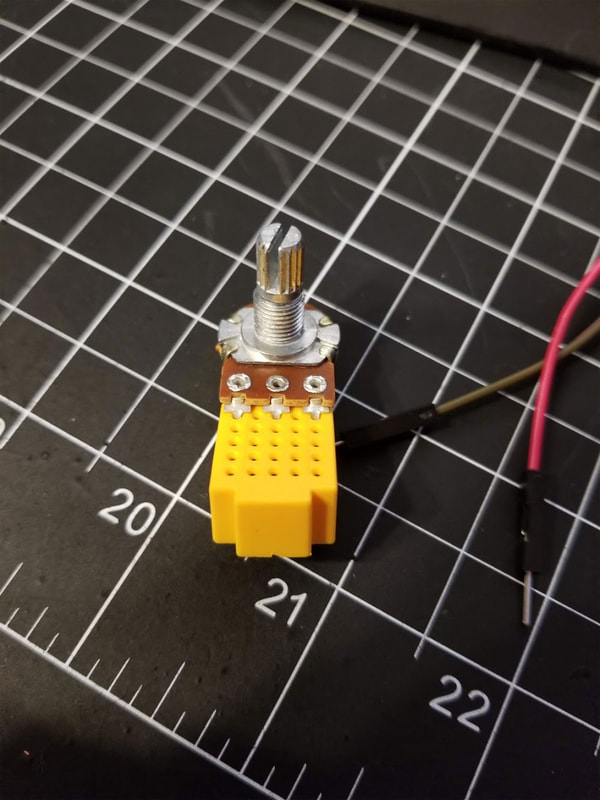
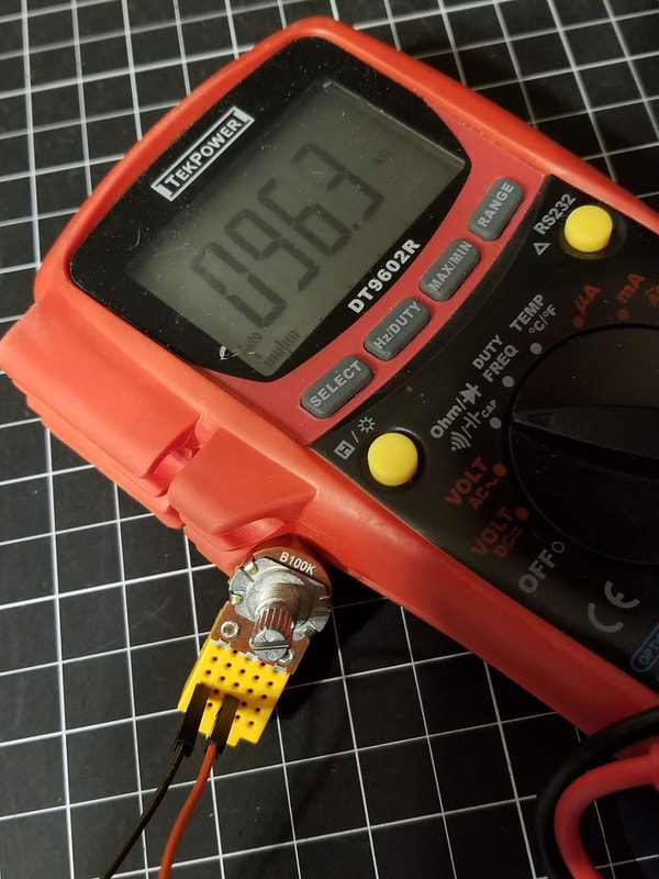
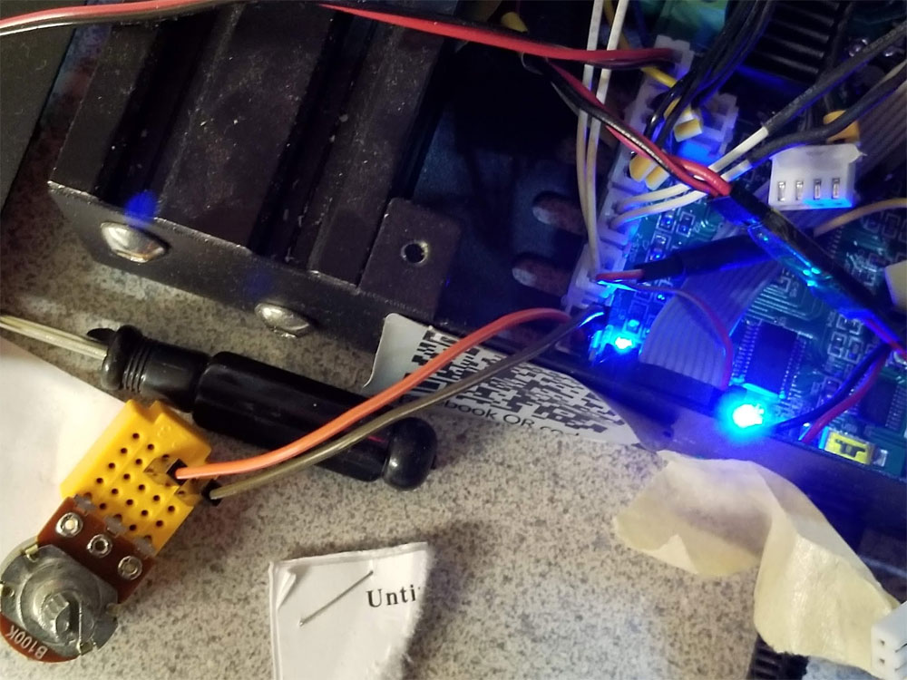
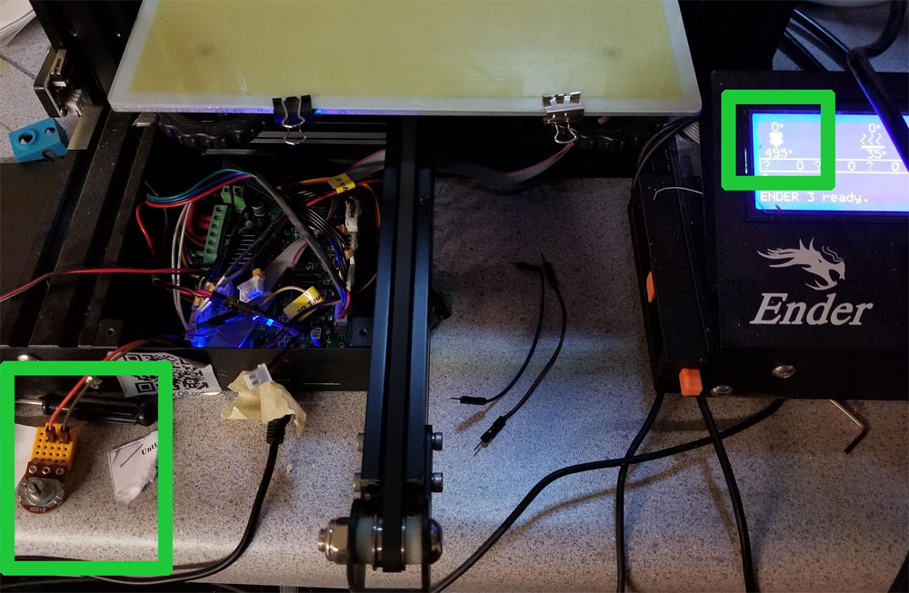
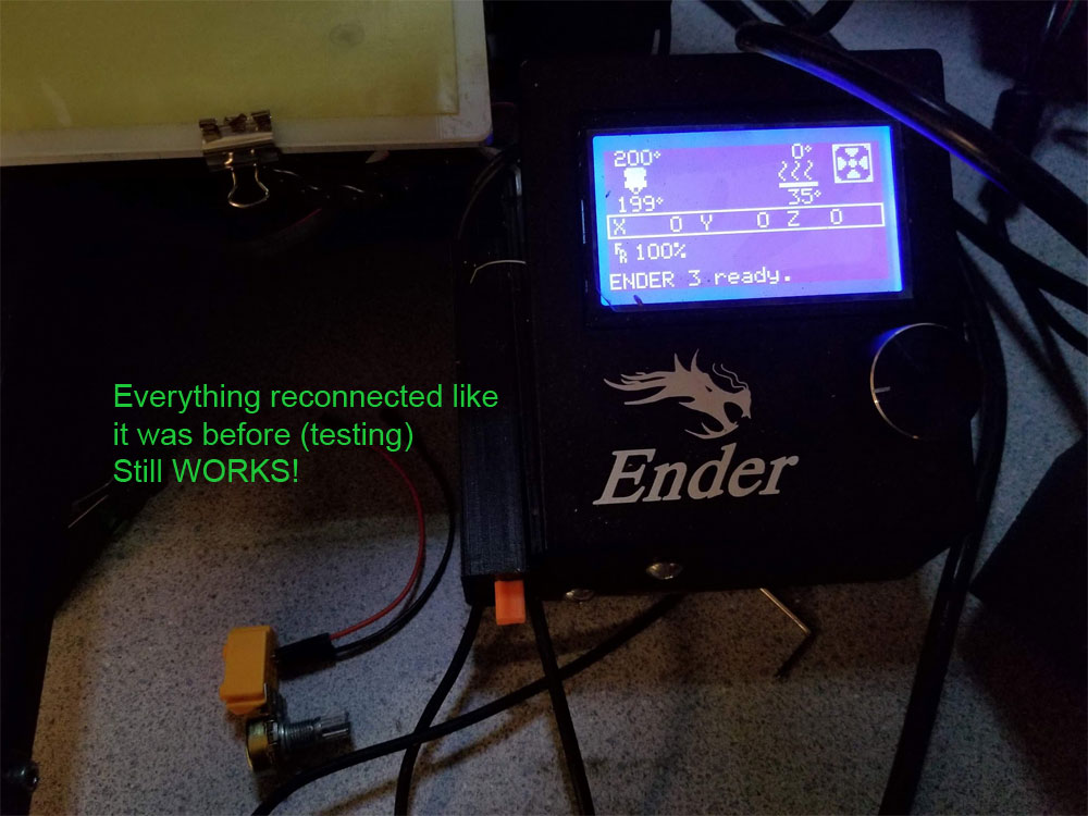
Below are some pics of the setup I used for this test. The first set is from the Ender3 and the 2nd is from the CR10S Pro. On the Ender3 I just unplugged the original thermistor and swapped in the 100K Ohm potentiometer in it's place using some dupont jumpers. I first set the potentiometer to around what my thermistor read at room temp (which was around 90Kohms) so when it was connected it would not trigger any thermal protection on the printer when I first tried it.
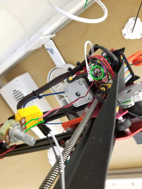
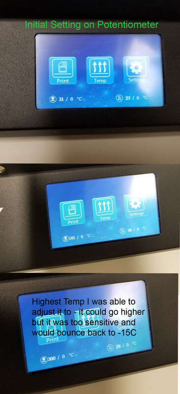
The CR10S Pro was trickier since the thermistor connects to a breakout board, and the dupont connectors did not fit (too large). Here I took a fan connector I had and just shoved the wires into the mini breadboard I was using the the potentiometer. It worked but was a bit clumsy, since I also jammed a couple jumpers in the breadboard to help hold the wires from the connector. As with the Ender3, I preset the potentiometer to around 90K Ohms before setting it up. On the CR10S Pro I noticed what is probably a software difference because adjustment of the potentiometer could cause the display to show -10C if I went to quickly which was easy since after 160C or so it was just a hairs breath of change needed to move the temps greatly (since it is a nonlinear scale and I used a linear pot). Still I was able to get it to read 185C and as high as 300C even as touchy as the adjustment was. When I put it back together I screwed up through and installed the thermistor in the connector which is one back from where it should have gone. Once I fixed that though it worked as before.


 RSS Feed
