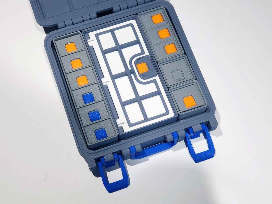
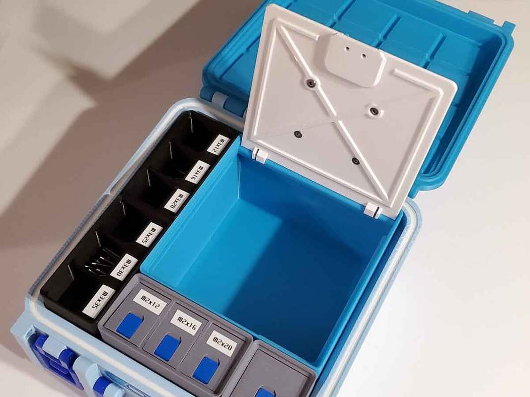
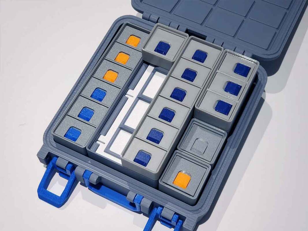
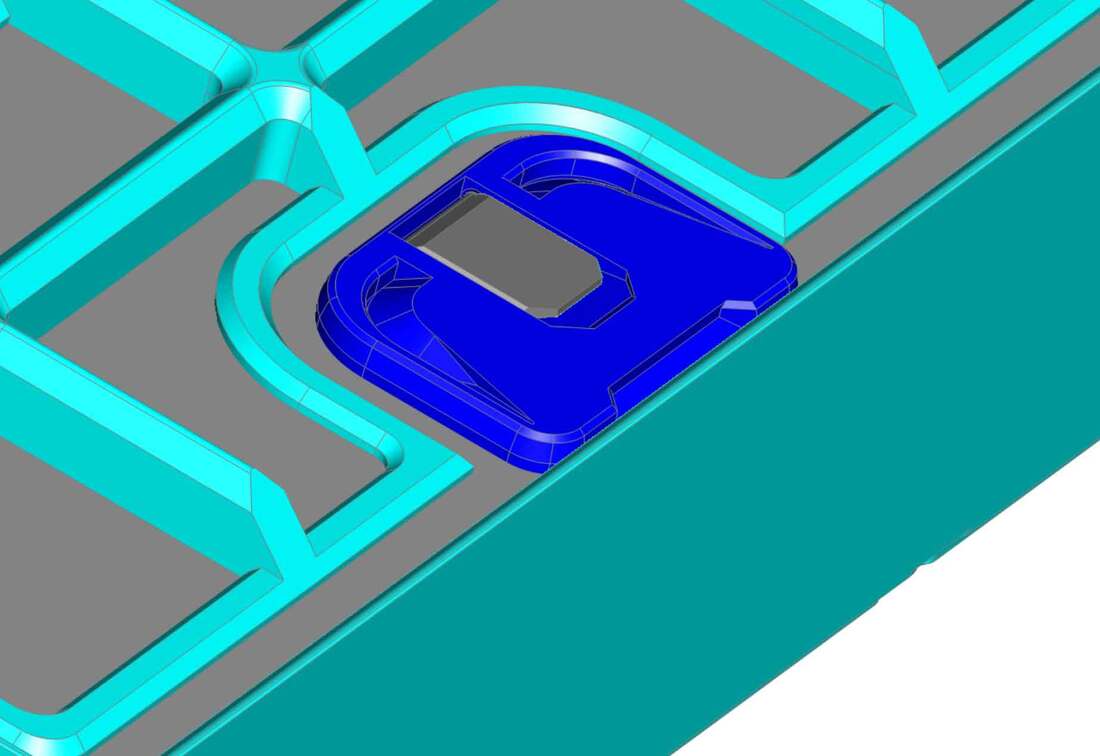
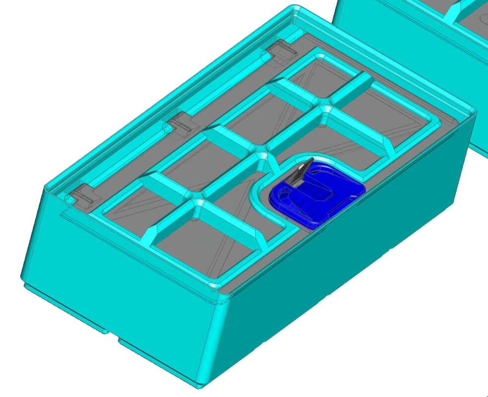
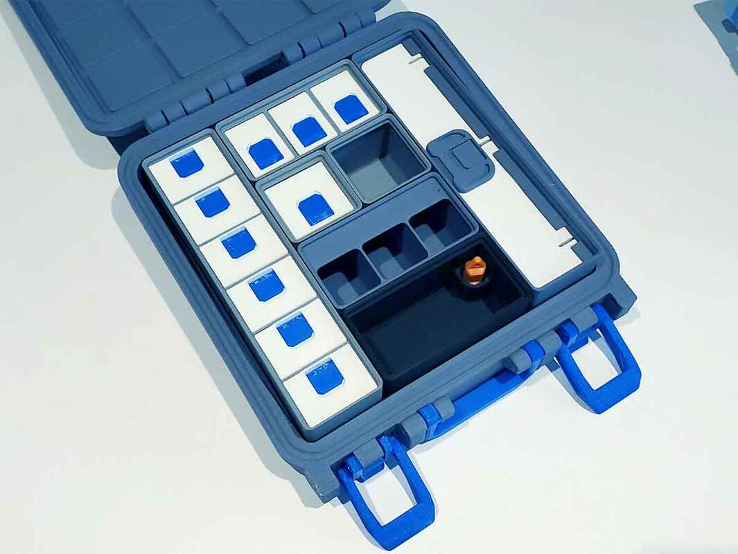
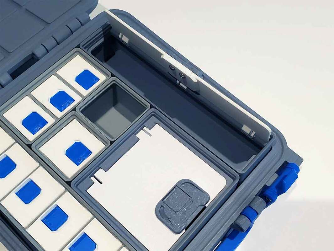
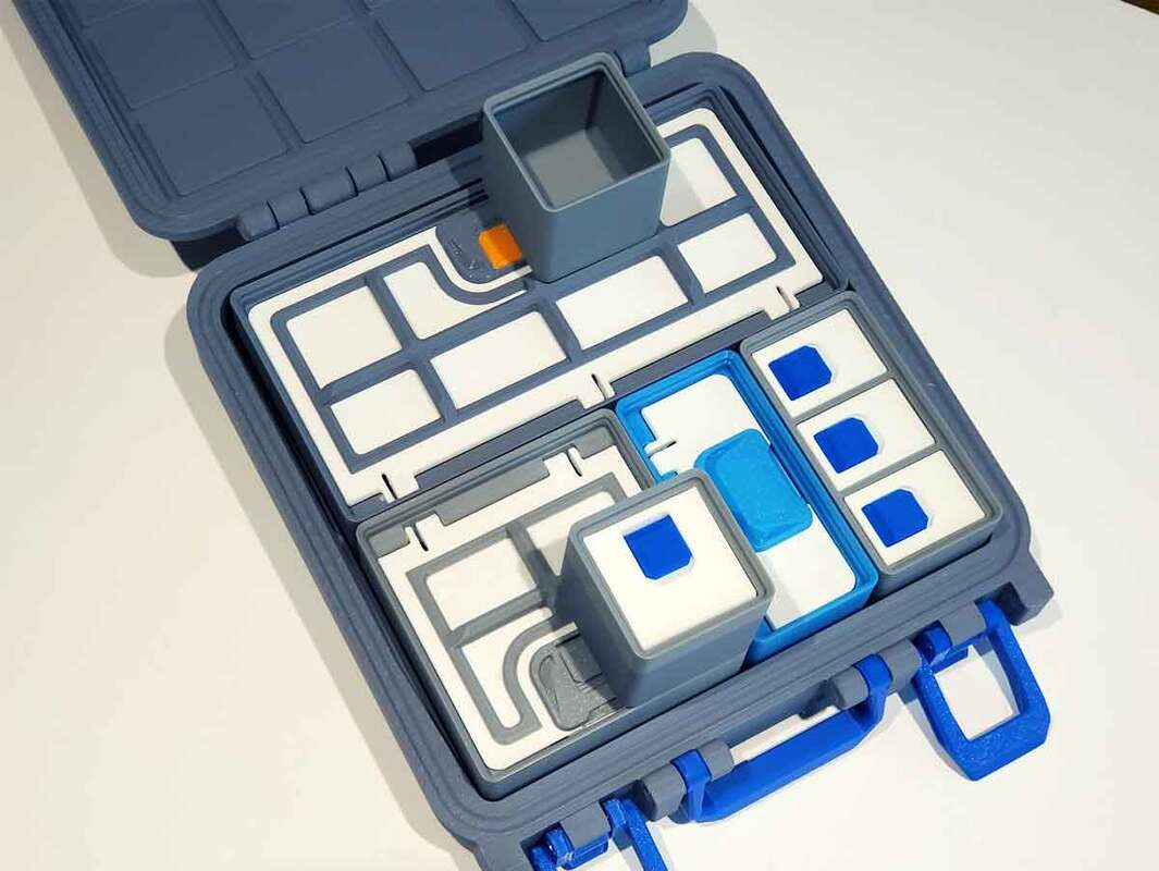
It is a shame that the 1x2 gridfinity case is really only useful as a test model (to help with dialing in settings before making a larger case). So when I looked at the case again today, I thought that maybe it would be cool to use as a watch case. So I checked around to see if there were any gridfinity 1x2 watch holders, and there were a few to choose from. This one looked pretty cool, but I had to slightly modify it to fit the 1x2 case, since it sits the watch too far forward to fit the case well. After that, it was just a matter of stretching the 1x2 case from a 6U to a 12U. I did that by stretching the top and base by 21mm (3U). That change in height means it won't likely work with a standard 12U gridfinity bin, but it should work fine for a watch insert (since the lid would not be able to open/close due to interference with a bin). With the extra room, I was also able to add a small label to the design. I'm gonna get this on the printer today as a test, and if it works out, it will be posted later this week, along with a remix of Luocheng Huang's Gridfinity Watch Stand, which is modified to fit this case.


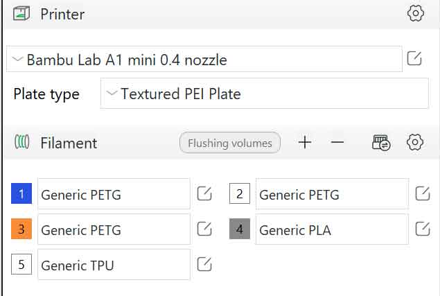
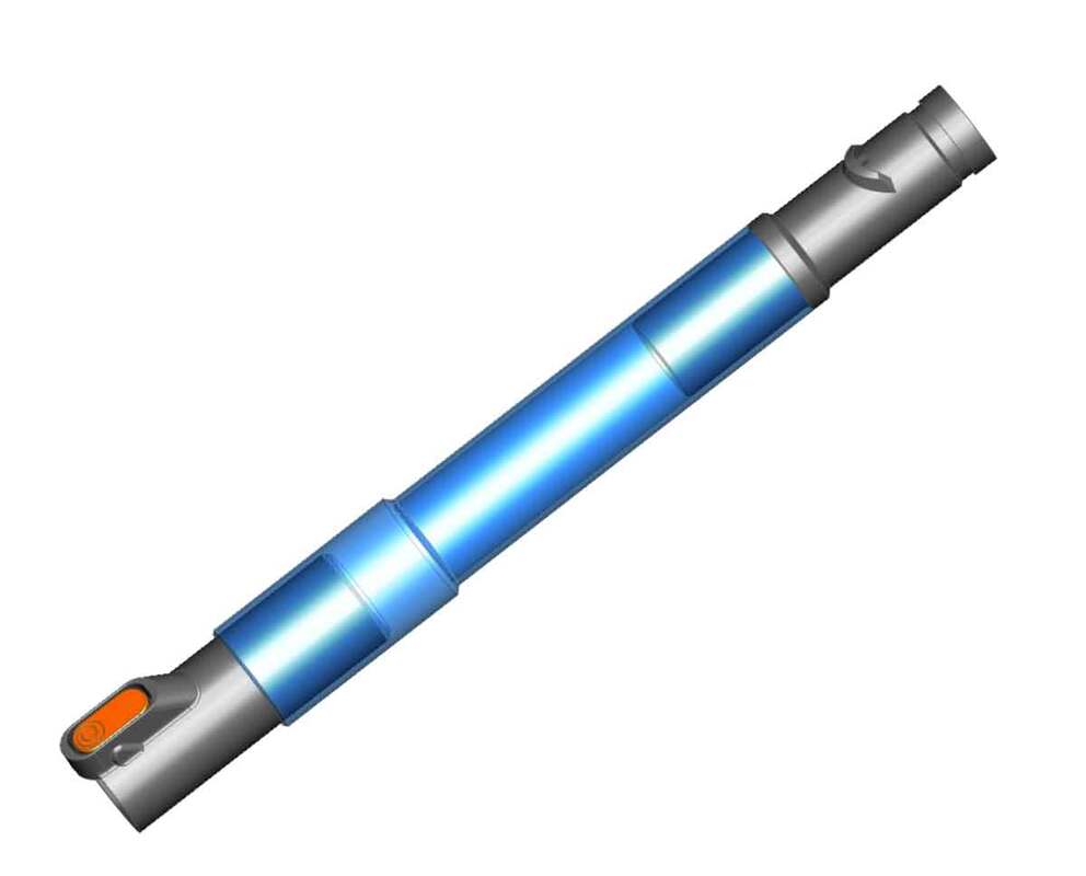
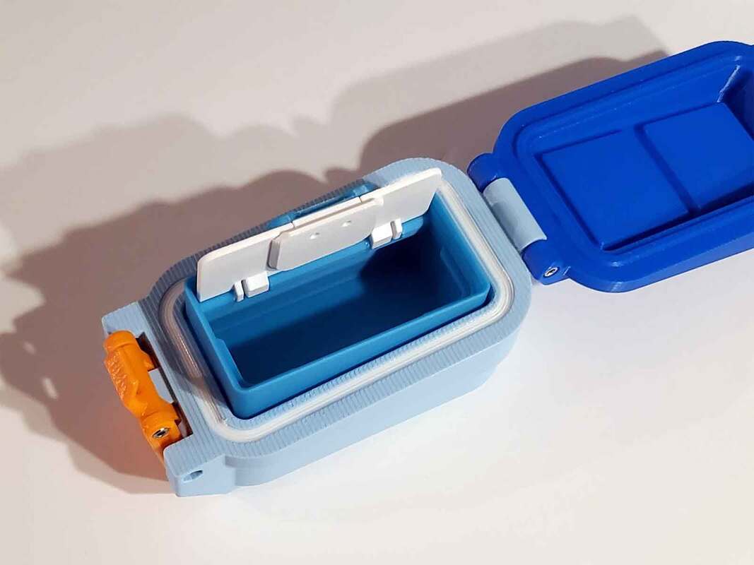
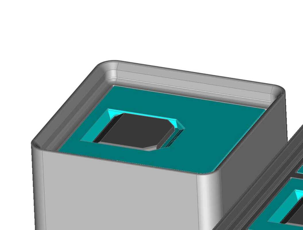
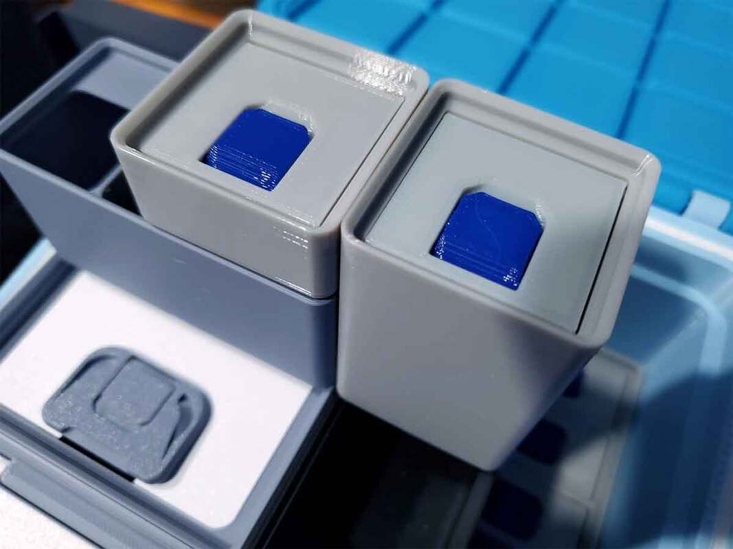
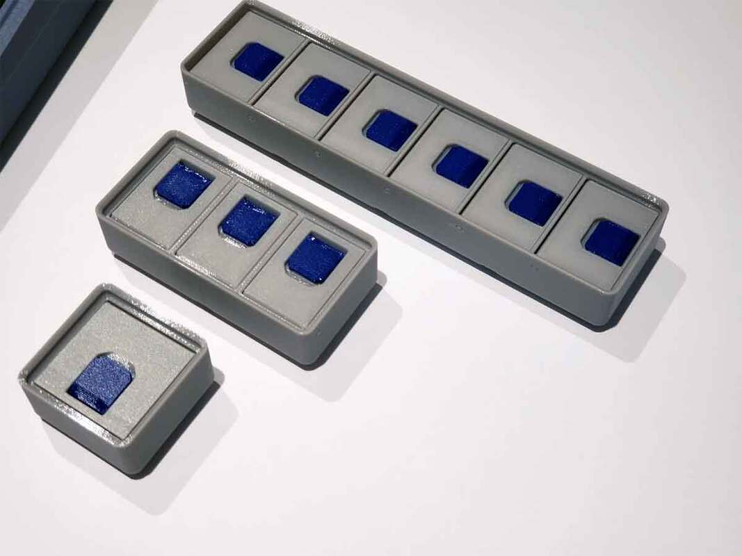
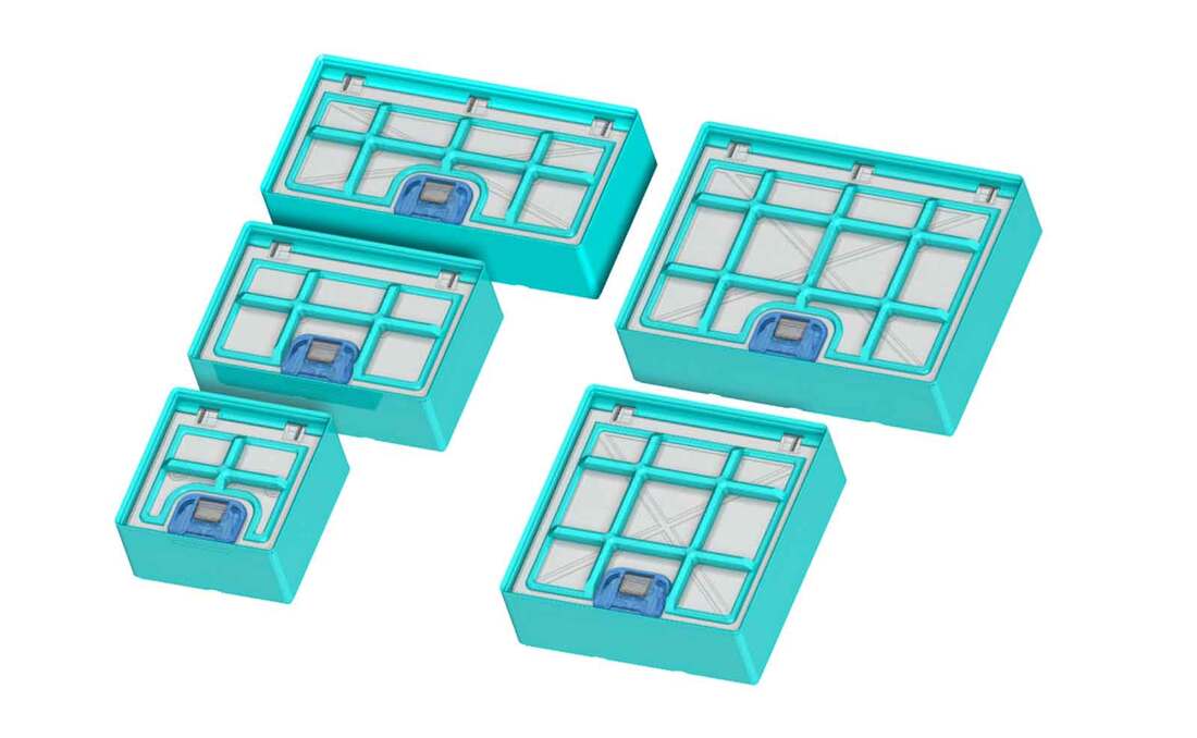
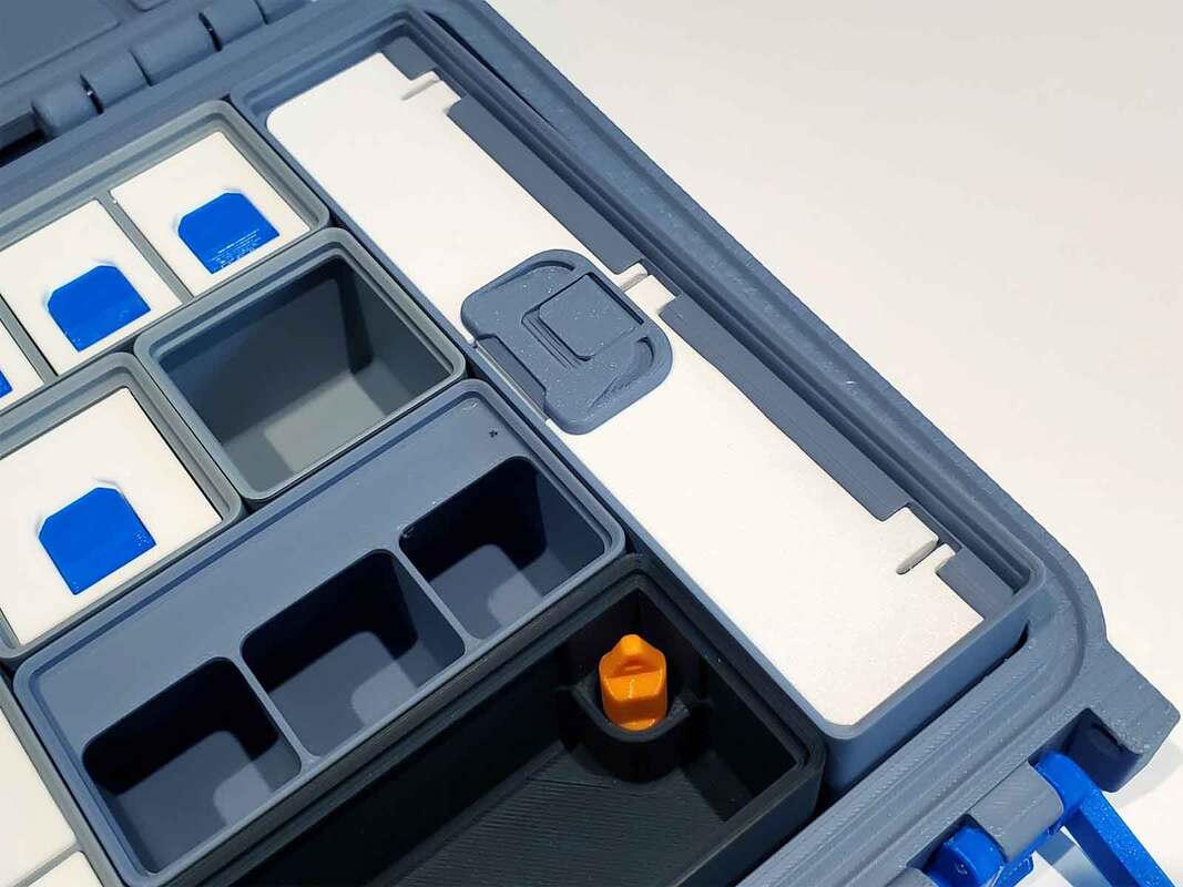
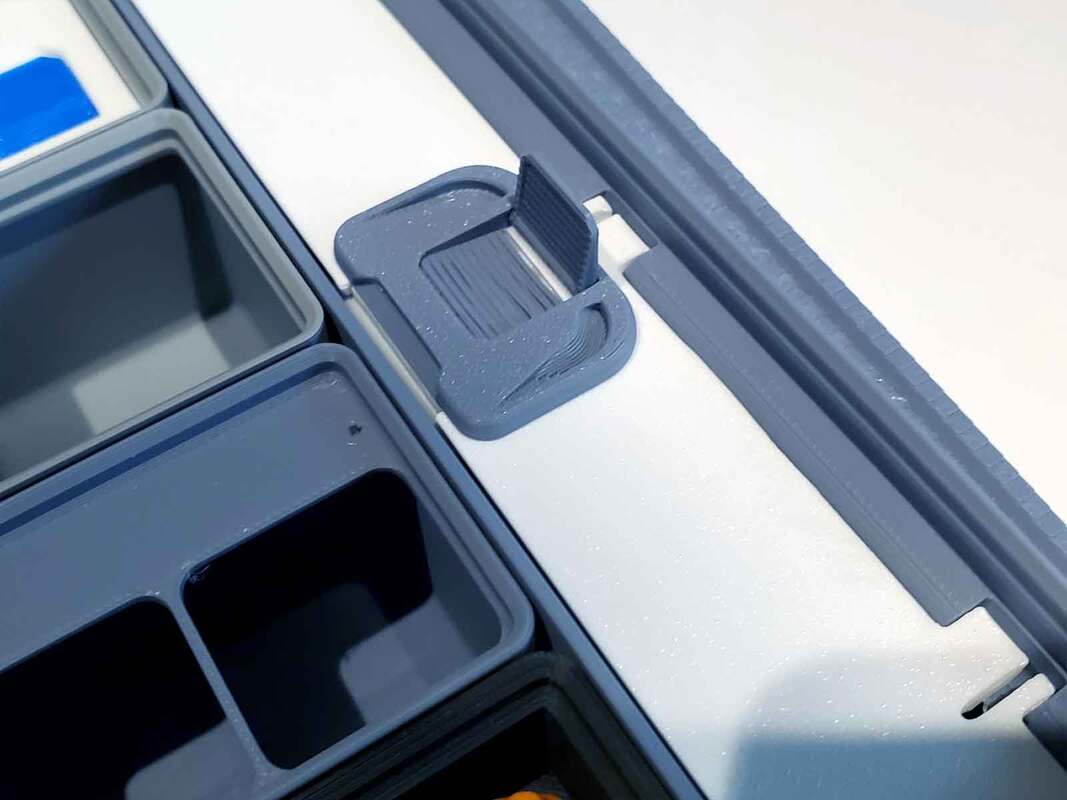
Update 5/1/2024: The prototype watch case is almost done, and there have been a couple changes since the initial design. I decided to widen the TPU gasket by a few mm, which I think will work better. If it does, I will update the 1x2 6U case with the new TPU gasket design, and my roll it out to the existing 20bin and 25bin BFS later as well. I also found that the remixed watch holder was too small for my watches, so added a few larger options. Once my test prints are done and tested, I will upload the watch holder case, and the watch holder insert as separate designs (since the watch holder insert has more general utility for folks who use Gridfinity).


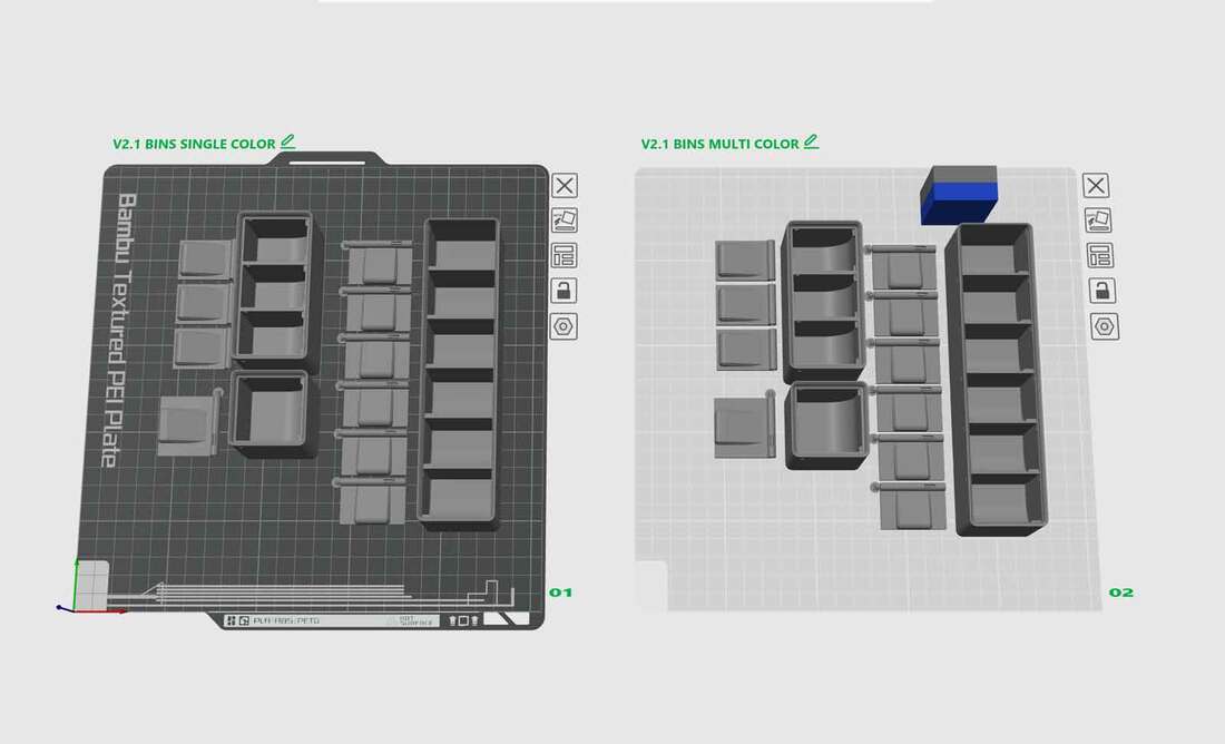
Update 5/1/2024: The models are now tested and uploaded:
https://makerworld.com/en/models/450801
https://www.printables.com/model/863677-gridfinity-1x2-watch-case-12u
https://makerworld.com/en/models/450801
https://www.printables.com/model/863677-gridfinity-1x2-watch-case-12u


 RSS Feed
